Table of Contents
Advertisement
Quick Links
Download this manual
See also:
Service Manual
Advertisement
Table of Contents

Related Manuals for Korg MS2000R


Summary of Contents for Korg MS2000R
-
Page 2: Data Handling
• Be careful not to let metal objects get into the equipment. If something does slip into the equipment, unplug the AC adaptor from the wall outlet. Then contact your nearest Korg dealer or the store where the equipment was purchased. -
Page 3: About This Manual
Thank you for purchasing the Korg MS2000/MS2000R analog modeling synthesizer. To ensure trouble-free enjoyment, please read this manual carefully and use the product correctly. About this manual How this manual is organized The MS2000/MS2000R owner’s manual is organized as fol- lows. -
Page 4: Table Of Contents
Connecting the AC adapter ...10 Connecting external devices ...10 Connecting pedals and switches ...10 Connecting MIDI devices ...10 1. Using the MS2000/MS2000R as a tone generator module 2. Playing an external MIDI device... 10 3. Setting the MIDI channel (preparations for playing) ... 11 Connections to the AUDIO IN jacks ...11... - Page 5 Parameter Guide...33 Program parameters ... 34 1. PROGRAM COMMON Parameters ...34 Page01: COMMON...34 2. NAME (Program Name) ...35 Page02: NAME ...35 3. SYNTH Parameters...35 VOICE ... 35 Page03: VOICE ...35 PITCH ... 36 Page04: PITCH ...36 OSCILLATOR ... 36 Page05: OSC 1...36 Page06: OSC 2...38 MIXER ...
- Page 6 Appendices ... 58 About MIDI ...58 MIDI messages transmitted and received by the MS2000/MS2000R MIDI channels ... 58 Note-on/off ... 58 Program change ... 58 Aftertouch... 58 Pitch bend ... 58 Control changes ... 59 Arpeggiator ... 63 System exclusive messages ... 63 Front panel knob/key control change assignments ...
-
Page 7: Basic Guide
Basic Guide Basic Guide Introduction Front and rear panel Connections Playing Editing... -
Page 8: Introduction
6. Vocoder function If a mic is connected to the AUDIO IN 2 jack, the MS2000/ MS2000R can be used as a four voice vocoder. In addition to using two 16-bank filter sets to simulate the vocoder sounds of classic equipment, you can create original vocoder sounds by shifting the filter frequency, or adjusting... -
Page 9: How A Program Is Structured
How a program is structured The programs of the MS2000/MS2000R can be classified in one of two categories depending on the Voice mode setting (LCD Edit mode Page 01A: COMMON “Mode”): synth programs whose “Mode” is Single/Dual/Split, and vocoder programs whose “Mode”... -
Page 10: Vocoder Programs
VIRTUAL PATCH VIRTUAL PATCH allows you to use not only EG or LFO, but even velocity (keyboard playing dynamics) or key- board tracking (the area of the keyboard you play) as mod- ulation sources which can be assigned to sound parameters for greater freedom in creating sounds. -
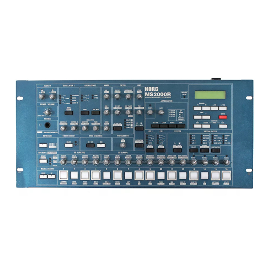
Page 11: Front And Rear Panel
Front and rear panel Front panel The characters printed inverse white on the front panel are vocoder program parameters (LCD Edit mode Page 01A: COM- MON “Mode” = Vocoder). MS2000 MS2000R... - Page 12 1 POWER/VOLUME [POWER/VOLUME] knob This turns the power on/off and adjusts the volume. 2 AUDIO IN ] knob This adjusts the input level of the AUDIO IN 1 jack. ] knob This adjusts the input level of the AUDIO IN 2 jack. 3 OSCILLATOR 1 [WAVE•...
- Page 13 [LATCH] key If this is on, the arpeggiator will continue playing even if you release your hand from the keyboard. [RANGE] key This sets the range in which the arpeggio will be played. [TYPE] key This selects the arpeggio type. 9 KEY &...
-
Page 14: Rear Panel
In Program Play mode, use these to select programs. In LCD Edit mode, use these to select pages. On the MS2000R, turning the [KEYBOARD] key on (LED lit) will cause these keys to function as a conve- nience MIDI keyboard, which you can use to play the program. -
Page 15: Control Panel (Ms2000)
6 Cable hook Wrap the AC adapter power cable around this to pre- vent accidental disconnection. When unwrapping the cable from the hook, do not apply excessive force to the cable. Control panel (MS2000) 1 PITCH BEND wheel This controls the pitch. 2 MODULATION wheel This controls the modulation depth. -
Page 16: Connections
If you wish to play an external MIDI device from the key- board of the MS2000 or from the SELECT [1]–[16] keys of the MS2000R, use a MIDI cable to connect the MIDI OUT connector of the MS2000/MS2000R to the MIDI IN connec- tor of the external MIDI device. -
Page 17: Setting The Midi Channel (Preparations For Playing)
3. Setting the MIDI channel (preparations for playing) If you are using the MS2000/MS2000R as a tone generator module, or if you are using the MS2000 as a master key- board to play an external MIDI device, you must set the... -
Page 18: Playing
The LCD screen will indicate the name of the selected =120 demo song. Tempo c. Exit the demo performance Press the [EXIT] key. You will return to Program Play mode. All demo songs: © 2000 korg Inc. — all rights reserved. = DEMO SONG #1 = Demo Song No.1... -
Page 19: Playing A Program
You can select programs in Program Play mode. If the LCD screen shows that you are in LCD Edit mode or Global mode, press the [EXIT] key. The method of changing the program or pitch differs between the MS2000 and the MS2000R. Also, the SELECT [1]–[16] keys can be used to play a program only on the MS2000R. -
Page 20: Ms2000R
Each time you press the key, the program number will decrease by one. 2. Use the SELECT [1]–[16] keys to play the program On the MS2000R, you can use the SELECT [1]–[16] keys to play the program. 1 Press the [KEYBOARD] key to make the key LED light. -
Page 21: Playing Arpeggios
2 Hold down a chord on the keyboard. An arpeggio will begin playing. On the MS2000R if you press the [KEYBOARD] key to make the key LED light, you will be able to use the SELECT [1]–[16] keys to play arpeggios ( p.14 “2. Use the SELECT [1]–[16] keys to play the program”). -
Page 22: Using Mod Sequence To Modify The Sound
Using MOD SEQUENCE to modify the sound 1. Playing a program in which MOD SEQUENCE is on Some of the factory preset programs contain sequence data. Here’s how to select and play these programs. 1 Select a program whose MOD SEQUENCE [ON/OFF] key is lit. -
Page 23: Using External Input
MIDI Synthesizer, sampler etc. 2 Turn on the power of both devices. 3 Set the MIDI channel of the MS2000/MS2000R and the MIDI channel of the connected MIDI device to the same channel. For details on setting the MS2000/MS2000R’s MIDI channel, refer to Basic Guide p.11, Connections “3. -
Page 24: Editing
Editing program parameters Programs consist of a large number of parameters. In order to create a program from scratch, you will need to under- stand all of these parameters. Instead of this, we suggest that you select a factory preset program, and try editing it in order to understand each parameter. -
Page 25: Switching Timbres
c. Select a parameter If Global mode Page 2C: Memory “Page Jump” is turned ON, operating a front panel knob in LCD Edit mode will cause the LCD screen to jump automatically to that param- eter. (With the factory settings, this is ON.) Press the CURSOR [√] or [®] key. -
Page 26: Editing A Synth Program
3 Press the [WRITE] key. The display will ask you for confirmation. 4 Press the [WRITE] key once again. When the LCD screen indicates “Completed,” the data has been written. Never turn off the power during the Write operation. This can damage the data. 5 Press the [EXIT] key. -
Page 27: Set The Volume Of Each Oscillator
e. Adjust the pitch of oscillator 2 in semitone units Rotate the [SEMITONE] knob. The LCD screen will show Page 06C: OSC 2 “Semitone.” The most common way to use this is to set oscillator 2 one or two octaves lower than the pitch of oscillator 1. 06C OSC 2 Semitone: f. -
Page 28: Specify Time-Varying Change In The Tone
5. Specify time-varying change in the tone Use EG 1 to create time-varying change in the cutoff fre- quency (FILTER “Cutoff”). If you wish to use the front panel knobs to adjust the EG 1 parameters, use the SEQ EDIT [SELECT] key to make the SEQ 1–3 LED’s go off. -
Page 29: Specify Time-Variant Changes In Volume
d. Apply distortion to the output Press the [DISTORTION] key. Each time you press the key, distortion will be turned on/off. When this is on ([DISTORTION] key LED lit), distortion will be applied. This is effective when you wish to pro- duce a hard\ harsh tone. -
Page 30: Make Lfo Settings
d. Adjust the speed at which the volume will decay after the note is released Rotate the EG 2 [RELEASE] knob. The LCD screen will show Page 11D: EG 2 “Release.” Rotating the knob toward the right (increasing the value) will make the volume decay more slowly, and rotating it toward the left (decreasing the value) will shorten the decay. -
Page 31: Make Mod Sequence Settings
10. Make MOD SEQUENCE settings a. Set SEQ COMMON parameters As preparation before creating the actual sequence data, the SEQ COMMON parameters are used to specify things such as the maximum number of steps in the sequence and the playback method. Use the [+/YES] [–/NO] keys to set the values. -
Page 32: Editing Effect Parameters
It is not possible to record the ARPEGGIATOR or EFFECTS knobs. Editing effect parameters The MS2000/MS2000R contains modulation, delay, and equalizer effects. Here we will explain how to make settings for the modulation effect and the delay. If you wish to use the front panel knobs to adjust the parameters of the modulation effect and delay, you must first use the SEQ EDIT [SELECT] key to turn off... -
Page 33: Delay Settings
2. Delay settings If you wish to use the front panel knobs to set the delay, you must first turn on the [MOD/DELAY] key LED. a. Select the delay type Press the SELECT [13] key. The LCD screen will show Page 23A: DELAY FX “Type.” Use the [+/YES] [–/NO] keys to select the delay type. -
Page 34: Editing Vocoder Program
Editing vocoder program Here’s the procedure for editing a program when in the Vocoder mode. For details on parameters that are the same as the synth pro- gram, please refer to the explanation for synth programs. Here we will explain the parameters that can be set only for a vocoder program. -
Page 35: Changing The Program Name
2 Use the sixteen knobs located beside adjust the output level of each filter. Rotating the knob far left is a setting of 0, and rotating it far right is a setting of 127 (max). f. Adjust the panpot (stereo location) of the carrier fil- ters 1 Press the ] key to make the... -
Page 36: Editing Global Parameters
2. Restoring settings to their factory state The factory settings are called the “preloaded data.” You can load this preloaded data to restore the MS2000/MS2000R’s programs and global settings to the factory state. When you load this data, all data in the MS2000/ MS2000R will be rewritten to the factory settings. -
Page 37: Synchronization With External Midi Devices
You can synchronize an external MIDI device such as a sequencer or rhythm machine to the tempo of the MS2000/ MS2000R arpeggiator. 1 Use a MIDI cable to connect the MS2000/MS2000R’s MIDI OUT connector to the external MIDI device’s MIDI IN connector ( p.10). - Page 38 When the transmission is completed, the display will indicate “Completed...” Please do not touch the knobs, keys, keyboard, or wheels etc. of the MS2000/MS2000R while the data is being transmitted. If you wish to receive a data dump on the MS2000/ MS2000R, you must first turn Global mode Page 2A:...
-
Page 39: Parameter Guide
Parameter Guide Parameter Guide Program parameters Global parameters... -
Page 40: Program Parameters
Timbre2 Timbre1 Vocoder By inputting an audio signal to the AUDIO IN 2 connector, you can use the MS2000/MS2000R as a four-voice vocoder. For details on the vocoder parameters, refer to p.49 “4. Vocoder Parameters.” B: Timbre Voice ... [1+3, 2+2, 3+1] This specifies the maximum number of notes that can be... -
Page 41: Name (Program Name)
The global MIDI channel (set in Global mode Page 3A: MIDI “MIDI Ch”) will be used as the MIDI transmit/ receive channel of the timbre. Select GLB if you are play- ing the MS2000/MS2000R from its own keyboard or from a connected MIDI keyboard. 01...16 The specified channel will be used as the MIDI transmit/... -
Page 42: Pitch
The range is –50 – +50 cents. C: Vibrato Int ... [–63...+63] Specify the depth of the vibrato effect that is applied when the modulation wheel (or for the MS2000R, the modulation wheel of a connected external MIDI device) is moved to the maximum position. - Page 43 This is a triangle, which has weaker overtones and a stron- ger fundamental than a sawtooth wave or square wave. It is suitable for mellow bass sounds. • Control1 You can modify the waveform by adjusting this value. A setting of 0 will produce a triangle wave, and a setting of 127 will produce a waveform with a pitch that is one octave and a fifth higher.
-
Page 44: Page06: Osc 2
Audio In If this is selected, the waveform input from the AUDIO IN 1 or AUDIO IN 2 jack will be used. This allows the MS2000/MS2000R to be used as an effect processor. • Control1 This adjusts the volume balance between AUDIO IN 1 and AUDIO IN 2. -
Page 45: Filter
FILTER Here are the filter-related parameters. Page08: FILTER A: Type FILTER TYPE ... [24LPF...12HPF] Select the filter type. 12LPF (–12dB/oct), 24LPF (–24dB/oct) LPF (Low Pass Filter) is the most commonly used type of file, which allows the frequencies lower than the cutoff fre- quency to pass and cuts the higher frequencies. -
Page 46: Page09: Amp
AMP (Amplifier) These are the volume-related parameters. Page09: AMP A: Level LEVEL ...[000...127] Adjust the volume of the timbre. If the “Mode” is Split/Dual, this setting will adjust the vol- ume balance between timbre 1 and timbre 2. B: Panpot PAN ... -
Page 47: Lfo (Low Frequency Oscillator)
Page 05B: OSC1 “Control 1.” LFO2 is internally connected as the modulation source for oscillator pitch via the modulation wheel (on the MS2000R, the modulation wheel of a connected external MIDI device). If you have difficulty hearing the effect of the LFO, increase the depth or intensity values of the modula- tion destination. -
Page 48: Virtual Patch
VIRTUAL PATCH Virtual Patch allows you to assign modulation sources such as EG and LFO to various parameters. Four such combinations can be made for each timbre. Page14: PATCH1 Page15: PATCH2 Page16: PATCH3 Page17: PATCH4 A: Source SOURCE ...[EG 1...MIDI 2] Select a modulation source. -
Page 49: Page19: Seq1
C: Run Mode... [1Shot, Loop] Specify whether the sequence will be looped for playback. 1 Shot The sequence will play back for only one cycle, and will hold the value of the last step. Loop The sequence will play back as a loop, using the sequence type specified by “Seq Type.”... -
Page 50: Effects
Value ... [–06...+06, –24...+24, –63...+63] Modify the value that is recorded at each step. These values are the amount of change that will be applied to the value of the parameter that is assigned to the sequence. –06...+06 This is the range when “Knob” is set to Step Length. –24...+24 This is the range when “Knob”... -
Page 51: Arpeggiator
D: HiEQGain...[–12.0...+12.0] Set the gain of the high-range equalizer. Excessively raising the equalizer gain parameters may cause the output to be distorted. ARPEGGIATOR These are the arpeggiator-related parameters. Page25: ARPEGGIO ON/OFF... [ON, OFF] Turn the arpeggiator on/off. This parameter can be set only by the front panel key. When this is ON, the key LED will light. -
Page 52: Utility
F: Key Sync... [ON, OFF] Specify whether the arpeggiator will be synchronized to the keyboard. If this is ON, the arpeggiator will always start from the beginning of the arpeggio pattern when you play the key- board. If you are performing together with other instru- ments, you can use this function to ensure that the arpeggio pattern is aligned with the beginning of the measure. - Page 53 3 Use the [+/YES] [–/NO] keys to select the copy source program. 4 Use CURSOR[®] to move the cursor to the copy source timbre. 5 Use the [+/YES] [–/NO] keys to select the copy source timbre. If the copy source program is Single, it will not be possi- ble to select the copy source timbre (only timbre 1 is available).
- Page 54 3 Use the [+/YES] [–/NO] keys to select the copy source program. 4 Use the CURSOR [®] key to move the cursor to the copy source timbre. 5 Use the [+/YES] [–/NO] keys to select the copy source timbre. If the copy source program is Single, it is not possible to select the copy source timbre (only timbre 1 is available).
-
Page 55: Vocoder Parameters
Use this setting when you wish to apply the vocoder effect only to the internal tone generator, or when you wish to use the MS2000/MS2000R as a tone generator and connect the output of another synthesizer to the AUDIO IN 1 jack. -
Page 56: Mixer
MIXER Page07: MIXER This sets the output level of the carrier. The level you specify here will be the input level to the band-pass filter of the car- rier. A: OSC 1 Level ...[000...127] Specify the output level of OSC1 (carrier). B: Inst Level ...[000...127] Specify the output level of the signal that is input from the... -
Page 57: Eg (Envelope Generator)
With a setting of 0, keyboard tracking will not affect the vol- ume. Keyboard Track operates according to the pitch that is controlled by pitch bend, transpose, and Mod Sequence. It is not affected by pitch changes produced by vibrato or Virtual Patch. - Page 58 B: InitTimbre Refer to “3. SYNTH Parameters.” C: Init ch Lvl This function initializes the output level for each filter of the carrier. When the levels are initialized, the output level value will be 127. Procedure 1 Press the SELECT [16] key, and then press the CUR- SOR [®] key twice.
-
Page 59: Global Parameters
The data that is output by the keyboard of the MS2000 or the SELECT [1]–[16] keys of the MS2000R will be sent to the MIDI OUT connector without being affected by the arpeggiator or by internal settings other than Octave. Data... -
Page 60: Page2: Memory
C: Clock ...[Internal...Auto] Make settings for synchronization with a connected external MIDI device. Internal The MS2000/MS2000R will be the master (the controlling device). A connected external MIDI device (e.g., sequencer) will synchronize to the sequence or arpeggiator of the MS2000/MS2000R. -
Page 61: Page4: Midi Filter
All note numbers will be received. Normally you will leave this set at ALL. If you have connected an MS2000 or an addition MS2000R to an MS2000R to increase the polyphony, set one unit to EVN and the other to ODD so that either one or the other will sound. -
Page 62: Page5: Ctrl Change
This lets you use the pedal to perform the functions of the front panel OCTAVE (or BANK/OCTAVE) [UP], [DOWN] keys. On the MS2000R, this is effective only for a perfor- mance using the SELECT [1]–[16] keys. Portmnt The pedal switch will function as a portamento on/off... -
Page 63: Page7: User Scale
C: A.Switch...[–, +] Select the polarity of the pedal switch that is connected. Set this to “–” if you are using a Korg PS-1 pedal switch or if you are not using a pedal switch. D: A.SwMode ... [UnLatch, Latch] Specify how a connected pedal switch will turn on/off. -
Page 64: Appendices
For exam- ple you can use the MS2000/MS2000R to control an external MIDI device, or conversely use an external MIDI device to control the MS2000/MS2000R to make it produce sound. -
Page 65: Control Changes
(Timbre Select) that specifies the timbre to which the messages will apply. When the MS2000/MS2000R receives a Timbre Select mes- sage, the timbre will switch according to the received value. A control change message is used for this Timbre Select message as specified by Global mode Page 4H: MIDI... -
Page 66: Controlling The Arpeggiator
2 Use data entry MSB (CC#6) [Bn, 06, mm] (n: channel, mm: parameter value) to specify the value. On the MS2000/MS2000R, only data entry MSB is used. Controlling the arpeggiator When arpeggiator settings are modified by the front panel keys or knobs, the following NRPN messages are transmitted. - Page 67 TIMBRE SELECT [SELECT] key. For the correspondence between the values of the message and the values of the MS2000/MS2000R parameter, refer to the table. Controlling the VIRTUAL PATCH 1–4 SOURCE •...
- Page 68 • When “Knob” = Step Length, data correspondences for both transmission and reception will be: 0...9: –6, 10...19: –5, 20..29: –4, 30...39: –3, 40...49: –2, 50...59: –1, 60...68: 0, 69...78: +1, 79...88: +2, 89...98: +3, 99...108: +4, 109...118: +5, 119...127: +6 •...
-
Page 69: Arpeggiator
• When “Knob=” other values, both transmission and reception will be: 0/1: –63, 2: –62...64: 0...127: +63 If you are using two MS2000/MS2000R units to trans- mit and receive these parameters, you must set the transmitting and receiving programs to the same set- tings. - Page 70 By performing a data dump, you can store various types of data on an external MIDI device, or rewrite the sounds or settings of a second MS2000/MS2000R. Data dumps can be performed on the MS2000/MS2000R as follows. • In Global mode Page 3F: MIDI Dump, select the type of data to be transmitted (1PROG, PROG, GLOBAL, ALL), and transmit the data dump.
-
Page 71: Front Panel Knob/Key Control Change Assignments
Front panel knob/key control change assignments Control changes can be assigned to each front panel knob/key of the MS2000/MS2000R so that the changes in sound as con- trolled by knob/key operations can be transmitted as performance data. Synth Parameter Vocoder Parameter... -
Page 72: How "Resolution" And "Sync Note" Values Correspond To Note Values
Control 2 values when OSC 1 Wave = DWGS When the synth parameter OSC 1 “Wave” is set to DWGS, the [CONTROL 2] knob will select the DWGS waveform. The value of the control change transmitted/received by operating the [CONTROL 2] knob corresponds to the parameter value as follows. -
Page 73: Voice Name List
Voice Name List Name Category Stab Saw Synth Hard Synth Lana Arpeggio Evolution Synth Pad Boost Bass Synth Bass Dirty Sync Synth Lead Zoop Mania Sequence Ice Field Bell Lounge Organ Keyboard MG Bass Synth Bass GatesOfHell Sequence PWM Strings Strings Turn Wheel Synth Lead... - Page 74 Name Category Ana Fuzz Synth Hard Water Edge Arpeggio Reactor Pad Synth Pad MS-101 Sqr Synth Bass Edge Lead Synth Lead Goa Trax Sequence Retro BD/SD Synth Drum Wet Reed Keyboard Fat Bass Synth Bass Flashlight Synth Motion Stream Pad Strings EP Fusion Ld Synth Lead...
- Page 75 Name Category Square Comp Synth Hard Krazy Arpy 2 Arpeggio Sweep Pad Synth Pad Sub Bass Synth Bass Phenomenon Synth Lead Ready 2 Air Sequence X-Mod Perc Bell BritishOrgan Keyboard 80's Bass Synth Bass Min.Deal Sequence Astral Vox Choir Rez Lead Synth Lead Soft Brass Synth Brass...
-
Page 76: Blank Chart
Program No. : Program Name: COMMON Mode: TimbreVoice: Split Point: Scale: PITCH Transpose: Tune: Vibrato Int: Bend Range: VOICE Assign : Priority: Trigger : Detune: EG 1 EG 2 EG Reset: EG Reset: SEQ COMMON SEQ1 LastStep : Knob: SeqType: Motion: Run Mode: Key Sync:... - Page 77 Timbre2 (Dual/Split) PITCH Transpose: Tune: Vibrato Int: Bend Range: VOICE Assign : Priority: Trigger : Detune: EG 2 EG 1 EG Reset: EG Reset: SEQ COMMON SEQ1 LastStep : Knob: SeqType: Motion: Run Mode: Key Sync: Resolution : SEQ2 Knob: Motion: SEQ3 Knob:...
-
Page 78: Vocoder Program
Program No. : Program Name: COMMON Mode: Vocoder Scale: PITCH Transpose: Tune: Vibrato Int: Bend Range: VOICE Assign : Priority: Trigger : Detune: EG 1 EG Reset: Vocoder Program AUDIO IN2 Gate Sense: Vel Sense: HPF Gate: KBD Track: ARPEGGIATOR Type: Range: Target:... -
Page 79: Troubleshooting
• Were any volume-related parameters set to a value of 0? ... p.38, 40 • Was the FILTER “Cutoff” set to 0? ... p.39 • If a pedal is connected to the MS2000/MS2000R, is the pedal in a position for which no sound will be pro- duced? Sound does not stop •... -
Page 80: Index
Index Symbols [+/YES] [–/NO] keys 7, 19, 30 A.Pedal A.SwFunc A.Switch A.SwMode Aftertouch All note off 3, 6, 40, 50 Amp Sw (EG 2/GATE) ANALYSIS FILTER ARPEGGIATOR 4, 6, 15, 45, 51 Assign 20, 35 ASSIGNABLE PEDAL jack 8, 10 SWITCH jack 8, 10 Attack (ATTACK) - Page 81 30, 54 Preloaded data Restoring settings to their factory state Priority Appendices ProgChg Program Select a program (MS2000) Select a program (MS2000R) Program change 54, 55, 58 Program Play mode 2, 12, 13, 18 Protect 30, 54 Pulse Pulse width modulation (PWM) 36...
- Page 82 SwapSeq SwapTimbre Swing 27, 46 Sync 3, 38 Sync control Sync Note DELAY FX SyncCtrl Synchronization Clock External MIDI devices Synth programs SYNTHESIS FILTER SystemEx Target 27, 45 Tempo (TEMPO) 15, 45 Tempo Sync 41, 44, 54 Threshold (THRESHOLD) 28, 49 TIMBRE TIMBRE SELECT Timbre Voice...
-
Page 83: Midi Implementation Chart
*3: Received according to the Global mode Page 5: CTRL CHANGE setting. *4: In addition to Korg exclusive messages, Inquiry messages, Master Volume messages and Master Fine Tune messages are also supported. *5: When the Global mode Page3C: MIDI “Clock” is internal, transmitted but not received. The opposite for External or Auto.
Need help?
Do you have a question about the MS2000R and is the answer not in the manual?
Questions and answers