Table of Contents
Advertisement
Quick Links
Advertisement
Table of Contents

Related Manuals for ICT PRT-ZX8-DIN


Summary of Contents for ICT PRT-ZX8-DIN
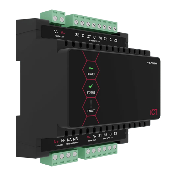
- Page 1 PRT-ZX8-DIN Protege DIN Rail 8 Input Expander Installation Manual...
- Page 2 Protege® and the Protege® Logo are registered trademarks of Integrated Control Technology Limited. All other brand or product names are trademarks or registered trademarks of their respective holders. Copyright © Integrated Control Technology Limited 2003-2021. All rights reserved. Last Published: 30-Apr-21 5:28 PM PRT-ZX8-DIN | Protege DIN Rail 8 Input Expander | Installation Manual...
-
Page 3: Table Of Contents
UL and ULC Installation Requirements UL/ULC Installation Cabinet Options Central Station Signal Receiver Compatibility List ULC Compliance Requirements CAN/ULC-S304 CAN/ULC-S559 UL Compliance Requirements UL1610 FCC Compliance Statements Industry Canada Statement PRT-ZX8-DIN | Protege DIN Rail 8 Input Expander | Installation Manual... - Page 4 Disclaimer and Warranty PRT-ZX8-DIN | Protege DIN Rail 8 Input Expander | Installation Manual...
-
Page 5: Introduction
Note: When connecting to a Protege GX system the DIN Rail 8 Input Expander requires firmware version 2.08.871 or higher. Without this the input expander will not register on a Protege GX controller. PRT-ZX8-DIN | Protege DIN Rail 8 Input Expander | Installation Manual... -
Page 6: Installation Requirements
The National Electrical Code, ANSI/NFPA 70 ⦁ The Canadian Electrical Code, Part I, CSA C22.1 ⦁ AS/NZS 2201.1 Intruder Alarm Systems ⦁ The Local Authority Having Jurisdiction (AHJ) ⦁ PRT-ZX8-DIN | Protege DIN Rail 8 Input Expander | Installation Manual... -
Page 7: Grounding Requirements
(RS-485 N+, N-, NA, NB) DIN Rail Enclosure Additional DIN Rail Enclosure(s) Controller Reader Expander Dialer’s Earth Ground Connection Input Expander Power Supply Output Expander AC Mains Wiring Earth Ground Link Connection PRT-ZX8-DIN | Protege DIN Rail 8 Input Expander | Installation Manual... - Page 8 Sector or Building #3 Note that the DIN rail enclosure earth terminal is connected to the power supply V- terminal. There must be only one single earth grounding point per system. PRT-ZX8-DIN | Protege DIN Rail 8 Input Expander | Installation Manual...
-
Page 9: Mounting
A Protege DIN rail module can be removed from the DIN rail mount using the following steps: Insert a flat blade screwdriver into the hole in the module tab clip. Lever the tab outwards and rotate the unit off the DIN rail mount. PRT-ZX8-DIN | Protege DIN Rail 8 Input Expander | Installation Manual... -
Page 10: Wiring Diagram
(Do not use extra wires to to the module serial number. The serial number can be found on the identification sticker on the power devices.) Max 900m (3000ft). side of the module. PRT-ZX8-DIN | Protege DIN Rail 8 Input Expander | Installation Manual... -
Page 11: Dc Power & Encrypted Module Network
RS-485 network cabling. End of Line Resistors: First Module on RS-485 Network Last Module on RS-485 Network 330R 330R From Next Previous Module Module PRT-ZX8-DIN | Protege DIN Rail 8 Input Expander | Installation Manual... -
Page 12: Inputs
No EOL Resistor Input Configuration To utilize the input duplex mode configuration shown below, simply assign additional inputs to the expander from within Protege to create a duplexed pair. PRT-ZX8-DIN | Protege DIN Rail 8 Input Expander | Installation Manual... -
Page 13: Trouble Inputs
Input Number Description Type Group ZXxxx:01-15 Reserved None None ZXxxx:16 Module Offline Module Offline System Replace 'xxx' with the appropriate address of the module that you are programming. PRT-ZX8-DIN | Protege DIN Rail 8 Input Expander | Installation Manual... -
Page 14: Address Configuration
The controller has a set limit on the number of modules of each type that it can support. When adding and configuring modules always refer to the Maximum Module Addresses table in the controller installation manual. PRT-ZX8-DIN | Protege DIN Rail 8 Input Expander | Installation Manual... -
Page 15: Led Indicators
The power indicator is lit whenever the correct module input voltage is applied across the N+ and N- terminals. State Description Constantly on (green) Correct module input voltage applied Constantly off Incorrect module input voltage applied PRT-ZX8-DIN | Protege DIN Rail 8 Input Expander | Installation Manual... -
Page 16: Error Code Indication
The serial number in the device is not valid. Return the unit to the distributor for replacement. Locked Device The module or system controller is a locked device and cannot communicate on the network. Return the unit to the distributor for replacement. PRT-ZX8-DIN | Protege DIN Rail 8 Input Expander | Installation Manual... -
Page 17: Mechanical Diagram
Mechanical Diagram The mechanical diagram shown below outlines the essential details needed to help ensure the correct installation of the input expander. PRT-ZX8-DIN | Protege DIN Rail 8 Input Expander | Installation Manual... -
Page 18: Mechanical Layout
The mechanical layout shown below outlines the essential details needed to help ensure correct installation and mounting. All measurements are shown in millimeters. 156.80 Front 156.80 42.40 72.00 42.40 Back 139.18 PRT-ZX8-DIN | Protege DIN Rail 8 Input Expander | Installation Manual... -
Page 19: Technical Specifications
Integrated Control Technology continually strives to increase the performance of its products. As a result these specifications may change without notice. We recommend consulting our website (www.ict.co) for the latest documentation and product information. -
Page 20: New Zealand And Australia
New Zealand and Australia General Product Statement The RCM compliance label indicates that the supplier of the device asserts that it complies with all applicable standards. PRT-ZX8-DIN | Protege DIN Rail 8 Input Expander | Installation Manual... -
Page 21: European Standards
Tests EMC (operational) according to EN 55032:2015 Radiated disturbance EN 55032:2015 Power frequency Magnetic field immunity tests (EN 61000-4-8) EN50131 In order to comply with EN 50131-1 the following points should be noted: PRT-ZX8-DIN | Protege DIN Rail 8 Input Expander | Installation Manual... - Page 22 ATTACK and EN-DIN-31, comply with the EN 50131 standards. Tamper protection against removal of the cover as well as removal from mounting is provided by tamper switch. Warning: Enclosures supplied by 3rd parties may not be EN50131-compliant, and should not be claimed as such. PRT-ZX8-DIN | Protege DIN Rail 8 Input Expander | Installation Manual...
-
Page 23: Ul And Ulc Installation Requirements
(DAXW/C) central station automation system software and compatible receiving equipment. CID Receiver via Onboard Modem: Any UL and ULC listed receiver that uses the Contact ID protocol. ⦁ PRT-ZX8-DIN | Protege DIN Rail 8 Input Expander | Installation Manual... -
Page 24: Ulc Compliance Requirements
Controller | Options in the Operator Reference Manual. The Test Report Time is Periodic option must be enabled. Refer to the section Controller | Options the Operator Reference Manual. PRT-ZX8-DIN | Protege DIN Rail 8 Input Expander | Installation Manual... - Page 25 Network access policies shall be set to restrict unauthorized network access and "spoofing" or "denial of service" attacks. ⦁ Internet Service Provider (ISP) The Internet Service Provider (ISP) providing service shall meet the following requirements: PRT-ZX8-DIN | Protege DIN Rail 8 Input Expander | Installation Manual...
-
Page 26: Can/Ulc-S559
The Contact ID Reporting Service must be enabled and the Service Mode must be configured to start with the operating system. Refer to the section Contact ID in the Operator Reference Manual. PRT-ZX8-DIN | Protege DIN Rail 8 Input Expander | Installation Manual... - Page 27 Any available dry relay contact on the Protege controller or output expander may be used for the FACP system, provided the selected output is programmed as the Report OK output. PRT-ZX8-DIN | Protege DIN Rail 8 Input Expander | Installation Manual...
- Page 28 NXOiInputivontactXi FireiInputimonitoringiRESETiPushixutton AiTheigviFgILioutputionitheiPoweriSupplyiMUST beiprogrammeditoifollowitheigviTroubleiInputiasifollows. i gviFgILi,iOPENionifail AiFireiareasishallibeiseparatedifromiburglariareasithroughiareaipartitioningX AiFireiInputsiZ53Z0ishallibeiusediexclusivelyiforifireimonitoringiandicannotibeiprogrammeditoiactivateitheibellioutput AFireiInputiZ)iNXOiPushixuttonitoibeiusediasimonitoringiresetiswitchX TypicaliInputivircuits EOL Resitor Input Configuration NXviInputivontact NXvi Valuei5 Valuei( MonitorediStatus Tamper Valuei( Valuei5 Open1ivlose1iTamper1iShort Open1ivlose1iTamper1iShort Open1ivlose1iTamper1iShort Open1ivlose1iTamper1iShort Open1ivlose1iTamper1iShort Open1ivlose1iTamper1iShort AiEOLiresistorimustibeiinstallediatitheiFireiglarmivontroliPaneliOutputX PRT-ZX8-DIN | Protege DIN Rail 8 Input Expander | Installation Manual...
- Page 29 Contact ID | Settings in the Operator Reference Manual. Fire inputs Z1-Z3 shall be used exclusively for fire monitoring and cannot be programmed to activate the ⦁ bell output. PRT-ZX8-DIN | Protege DIN Rail 8 Input Expander | Installation Manual...
-
Page 30: Ul Compliance Requirements
In the Protege system, the reporting service selected as Contact ID must have the number of attempts programmed to 5 attempts. The following options are required: PRT-ZX8-DIN | Protege DIN Rail 8 Input Expander | Installation Manual... - Page 31 If a flexible cord is used to connect to line voltage, strain relief must be provided for the cord inside the ⦁ enclosure or at the knockout. ⦁ The power supply is not intended to be mounted on the exterior of vault, safe, or stockroom. PRT-ZX8-DIN | Protege DIN Rail 8 Input Expander | Installation Manual...
-
Page 32: Fcc Compliance Statements
NOTE: THE GRANTEE IS NOT RESPONSIBLE FOR ANY CHANGES OR MODIFICATIONS NOT EXPRESSLY APPROVED BY THE PARTY RESPONSIBLE FOR COMPLIANCE. SUCH MODIFICATIONS COULD VOID THE USER’S AUTHORITY TO OPERATE THE EQUIPMENT. PRT-ZX8-DIN | Protege DIN Rail 8 Input Expander | Installation Manual... -
Page 33: Industry Canada Statement
Industry Canada Statement ICES-003 This is a Class A digital device that meets all requirements of the Canadian Interference Causing Equipment Regulations. CAN ICES-3 (A)/NMB-3 (A) PRT-ZX8-DIN | Protege DIN Rail 8 Input Expander | Installation Manual... - Page 34 Integrated Control Technology Ltd nor its employees shall be liable under any circumstances to any party in respect of decisions or actions they may make as a result of using this information. In accordance with the ICT policy of enhanced development, design and specifications are subject to change without notice.
- Page 35 Disclaimer: Whilst every effort has been made to ensure accuracy in the representation of this product, neither Integrated Control Technology Ltd nor its employees shall be liable under any circumstances to any party in respect of decisions or actions they may make as a result of using this information. In accordance with the ICT policy of enhanced development, design and specifications are subject to change without notice.
Need help?
Do you have a question about the PRT-ZX8-DIN and is the answer not in the manual?
Questions and answers