Table of Contents
Advertisement
Quick Links
Advertisement
Table of Contents

Related Manuals for ICT Protege PRT-PX8-DIN


Summary of Contents for ICT Protege PRT-PX8-DIN
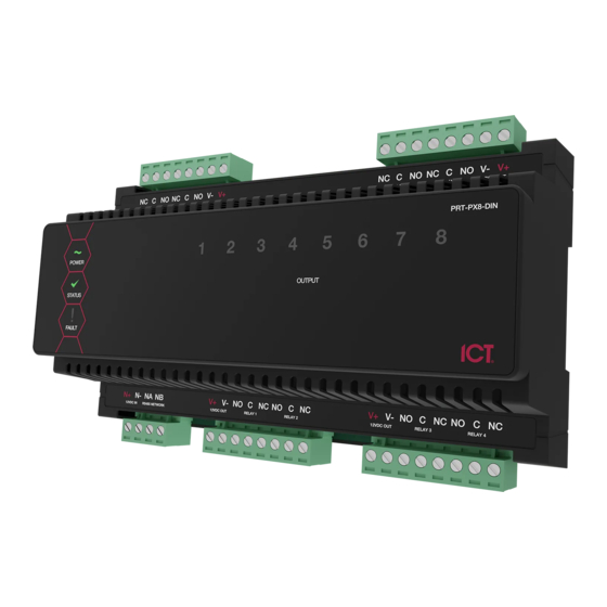
- Page 1 Protege DIN Rail 8 PGM Output Expander Installation Manual...
- Page 2 The specifications and descriptions of products and services contained in this document were correct at the time of printing. Integrated Control Technology Limited reserves the right to change specifications or withdraw products without notice. No part of this document may be reproduced, photocopied, or transmitted in any form or by any means (electronic or mechanical), for any purpose, without the express written permission of Integrated Control Technology Limited.
-
Page 3: Table Of Contents
Contents Introduction _______________________________________________________________ 5 Installation Requirements ___________________________________________________ 6 Grounding Requirements ___________________________________________________ 7 3.1 Safety Grounding ......................7 3.2 Earth Ground Connection ....................7 Mounting _________________________________________________________________ 9 4.1 Removal ......................... 9 4.2 Wiring Diagram ......................10 DC Power &... - Page 4 CAN/ULC-S559-04 ...................... 26 15.3 UL Compliance Requirements ..................27 UL1610 ........................27 UL294 .......................... 29 FCC Compliance Statements ______________________________________________ 30 Industry Canada Statement ________________________________________________ 31 Disclaimer and Warranty __________________________________________________ 32 Contact _________________________________________________________________ 33 ...
-
Page 5: Introduction
Online and remote upgradable firmware For more information on the Protege DIN Rail 8 Output Expander and other Integrated Control Technology products please visit the Integrated Control Technology website (http://www.ict.co). Protege DIN Rail 8 PGM Output Expander | Installation Manual... -
Page 6: Installation Requirements
Installation Requirements This equipment is to be installed in accordance with: The Product installation instructions UL 681 - Installation and Classification of Burglar and Holdup Systems UL 827 - Central-Station Alarm Services CAN/ULC-S301, Central and Monitoring Station Burglar Alarm Systems ... -
Page 7: Grounding Requirements
Grounding Requirements An effectively grounded product is one that is intentionally connected to earth ground through a ground connection or connections of sufficiently low impedance and having sufficient current-carrying capacity to prevent the build up of voltages which may result in undue hazard to connected equipment or to persons. - Page 8 DIN Rail Ground Connections (one or more cabinets installed in the same room) Module Network (RS-485 N+, N-, NA and NB) DIN Rail Enclosure Additional DIN Rail Enclosure (s) PRT-RDM2-DIN Controller Reader Expander Dialer’s Earth Ground Connection PRT-PSU-DIN PRT-PSU-DIN Power Supply Input Expander Output Expander AC Mains Wiring...
-
Page 9: Mounting
Mounting The Output Expander is designed to mount on standard DIN Rail either in dedicated DIN cabinets or generic DIN Rail mounting strip. When installing the Output Expander ensure that there is adequate clearance around all sides of the device and that air flow to the vents of the unit is not restricted. -
Page 10: Wiring Diagram
4.2 Wiring Diagram Output Expander System Controller or module supplying power to networked devices Lock Power Supply Lock Power Supply Electric Locking Device White Blue 8 Ohm 30W Next modules Black Siren or 1.1A on network (Typical) CAUTION: INCORRECT WIRING MAY RESULT IN Description DAMAGE TO THE UNIT Green... -
Page 11: Dc Power & Encrypted Module Network
DC Power & Encrypted Module Network The Output Expander incorporates encrypted RS-485 communications technology, and both module and network power are supplied by the N+ and N- terminals. Network communications input from the Controller or previous module Connection of the communications and DC supply should be performed according to the diagram shown above. -
Page 12: Outputs
Outputs The Output Expander has 8 Programmable Outputs (PGMs). These outputs are used to activate bell sirens, lighting circuits, door locks, relay accessory products and other automation points. 6.1 PGM Outputs 1 to 8 The 8 PGM Outputs each have a FORM C output relay. The connection example below shows the control of an external LED indicator. -
Page 13: Address Configuration
Address Configuration The address of the Output Expander is configured via programming and will require entry of the module serial number. The serial number can be found on the identification sticker on the product. Refer to the Protege System Controller installation manual for address programming details. Protege DIN Rail 8 PGM Output Expander | Installation Manual... -
Page 14: Led Indicators
LED Indicators The Output Expander includes comprehensive front panel diagnostic indicators that can aid the installer in diagnosing faults and conditions. In some cases an indicator may have multiple meanings depending on the status indicator display at the time. 8.1 Status Indicator The Status indicator displays the module status. -
Page 15: Output Indicators
8.4 Output Indicators The Output indicators will show the status of the outputs. State Description Constantly on (red) Output is ON Constantly off Output is OFF Protege DIN Rail 8 PGM Output Expander | Installation Manual... -
Page 16: Error Code Indication
Error Code Indication When the module attempts to register or communicate with the system controller a registration error can be generated indicating that it was not successful. 9.1 Error Code Display The following table is only valid if the FAULT indicator is CONSTANTLY ON and the STATUS indicator is FLASHING RED. -
Page 17: Mechanical Diagram
10 Mechanical Diagram The mechanical diagram shown below outlines the essential details needed to help ensure the correct installation of the Output Expander. 12VDC Pass Through PGM Outputs 5 & 6 PGM Outputs 7 & 8 12VDC Pass Through NC C NO NC C NO V- V+ NC C NO NC C NO V- V+ RELAY 8 RELAY 7... -
Page 18: Mechanical Layout
11 Mechanical Layout The mechanical layout shown below outlines the essential details needed to help ensure the correct installation of the Output Expander. 156.8mm FRONT BACK 143.5m m 156.8m m Protege DIN Rail 8 PGM Output Expander | Installation Manual... -
Page 19: Technical Specifications
Integrated Control Technology continually strives to increase the performance of its products. As a result these specifications may change without notice. We recommend consulting our website (http://www.ict.co) for the latest documentation and product information. -
Page 20: New Zealand And Australia
13 New Zealand and Australia General Product Statement The RCM compliance label indicates that the supplier of the device asserts that it complies with all applicable standards. Protege DIN Rail 8 PGM Output Expander | Installation Manual... -
Page 21: European Standards
14 European Standards CE Statement Conforms to European Union (EU) Low Voltage Directive (LVD) 2014/35/EC, Electro-Magnetic Compatibility (EMC) Directive 2014/30/EU and RoHS Recast (RoHS2) Directive: 2011/65/EU. The CE mark indicates that this product complies with the European requirements for safety, health, environmental and customer protection. - Page 22 EN 50131 In order to comply with EN 50131-1 the following points should be noted: Ensure for Grade 3 compliant systems, the minimum PIN length is set for 6 digits. To comply with EN 50131-1 Engineer access must first be authorized by a user, therefore Installer codes will only be accepted when the system is unset.
-
Page 23: Ul And Ulc Installation Requirements
15 UL and ULC Installation Requirements Only UL / ULC listed compatible products are intended to be connected to a UL / ULC listed control system. 15.1 UL/ULC Installation Cabinet Options UL/ULC Central Station Fire Monitoring, Central Station Alarm Installations Cabinet Model Manufacturer UL/ULC Installation Listings... - Page 24 Multiplex System and Poll Time The PRT-CTRL-DIN is compatible with the ICT ArmorIP Internet Monitoring Receiver. Poll Time must be set to 40 seconds and the Grace Time must be set to 20 seconds. In the Protege System, the reporting service must be configured to 40 seconds. The following options are required for the service selected as Report IP type: ...
- Page 25 The Ethernet Link Failure Trouble Input must be programmed. The Trouble Input Area must be armed. Refer to the section Trouble Inputs | Areas and Input Types the ProtegeGX Operator Reference Manual (227-1500-000). The Log Modem Events to Event Buffer option must be selected in the Contact ID Reporting Service. ...
-
Page 26: Can/Ulc-S319-05
ArmorIP detects the reception of any invalid packet on the programmed port as a potential system compromise attempt. Each compromise attempt sends a notification to the receiver, and logs a Compromise Attempt event under the Live Panel Events. The event is sent with the following details: ... -
Page 27: Ul Compliance Requirements
In the ArmorIP Internet Monitoring Software the Poll Time must be set to 40 seconds and the Grace Time must be set to 20 seconds. Refer to the section Poll/Grace Time in the ArmorIP Internet Monitoring Application User Manual (227-5500-000). ... - Page 28 Signals between the premises control unit and the receiving equipment, when not carried by wireless means, shall be protected by the following method: Onboard modem telco connection must be dedicated to the PRT-CTRL-DIN. Ethernet connection to the Internet Service Provider (ISP) with a fixed IP Address must be dedicated to the PRT-CTRL-DIN.
-
Page 29: Ul294
ArmorIP detects the reception of any invalid packet on the programmed port as a potential system compromise attempt. Each compromise attempt sends a notification to the receiver, and logs a Compromise Attempt event under the Live Panel Events. The event is sent with the following details: ... -
Page 30: Fcc Compliance Statements
16 FCC Compliance Statements FCC PART 15, WARNINGS: INFORMATION TO USER This equipment has been tested and found to comply with the limits for a Class A digital device, pursuant to Part 15 of the FCC Rules. These limits are designed to provide reasonable protection against harmful interference in a residential installation. -
Page 31: Industry Canada Statement
17 Industry Canada Statement This class A digital apparatus complies with Canadian ICES-003. Cet appareil numérique de la classe A est conforme à la norme NMB-003 du Canada. CAN ICES-3 (A)/NMB-3(A) Protege DIN Rail 8 PGM Output Expander | Installation Manual... -
Page 32: Disclaimer And Warranty
In accordance with the Integrated Control Technology policy of enhanced development, design and specifications are subject to change without notice. Refer to the Integrated Control Technology website (http://www.ict.co) for the latest information. -
Page 33: Contact
19 Contact Integrated Control Technology welcomes all feedback. Please visit our website (http://www.ict.co) or use the contact information below. Integrated Control Technology P.O. Box 302-340 4 John Glenn Ave North Harbour Post Centre Rosedale Auckland North Shore City 0632 New Zealand... - Page 34 Integrated Control Technology Limited 4 John Glenn Avenue, Rosedale, Auckland 0632 PO Box 302-340, North Harbour, Auckland 0751, New Zealand Email: sales@ict.co Toll Free: (0800) 428 111 Phone: 64 (9) 476 7124 AMERICAS Integrated Control Technology (USA) LLC 5265 S Rio Grande Street, Suite 201, Littleton, CO 80120 Email: ussales@ict.co Toll Free: (855) 428 9111 Phone: 720 442 0767...
Need help?
Do you have a question about the Protege PRT-PX8-DIN and is the answer not in the manual?
Questions and answers