Satel INTEGRA 128-WRL Installer Manual
Alarm control panels
Hide thumbs
Also See for INTEGRA 128-WRL:
- Programming manual (95 pages) ,
- Installer manual (36 pages) ,
- Manual (117 pages)

Related Manuals for Satel INTEGRA 128-WRL


Summary of Contents for Satel INTEGRA 128-WRL
- Page 1 INSTALLER MANUAL SATEL sp. z o.o. ul. Budowlanych 66 80-298 Gdańsk POLAND tel. + 48 58 320 94 00 www.satel.eu integra-wrl_i_en 08/21...
- Page 2 Changes, modifications or repairs not authorized by the manufacturer shall void your rights under the warranty. SATEL aims to continually improve the quality of its products, which may result in changes in their technical specifications and software. Current information about the changes being introduced is available on our website.
-
Page 3: Keypads
Changes made to the firmware version 1.20 Keypads Support for new keypads: INT-TSG2 and INT-TSH2. Outputs New option: AC (for the 28. AC LOSS FAST LOSS MAINBOARD IMMEDIATE type outputs). Reporting New option for the SIA-IP format: E VENT INDEPENDENT POOLING... -
Page 4: Table Of Contents
Installer Manual SATEL CONTENTS General ..........................3 Features ..........................3 Keypads ..........................5 Features of keypads with mechanical keys ..............6 Expansion modules ......................6 Modules to be connected to the keypad bus ............... 6 Modules to be connected to the expander bus ............. 7 Wireless devices supported by the control panel ............ -
Page 5: General
SATEL INTEGRA 128-WRL 1. General This manual applies to the INTEGRA 128-WRL control panel. The manual also describes keypads compatible with the control panel and other devices that may be included in the security alarm system. The INTEGRA 128-WRL control panels meet the requirements of the following standards: –... -
Page 6: Voice Messages
Installer Manual SATEL – event messaging, – checking the alarm system status by telephone (DTMF or SMS), – remote control of the alarm system outputs by telephone (DTMF), – remote control of the alarm system using SMS messages. • Built-in GSM modem to allow remote operation and programming of the alarm system (300 bps or CSD transmission). -
Page 7: Keypads
• Switching power supply with short-circuit protection, provided with a battery status supervision and low battery disconnect system. 3. Keypads The INTEGRA 128-WRL control panel supports the following keypads: INT-TSG – touchscreen keypad, INT-TSG2 – touchscreen keypad, INT-TSH – touchscreen keypad, INT-TSH2 –... -
Page 8: Features Of Keypads With Mechanical Keys
Installer Manual SATEL INT-KWRL – wireless LCD keypad with mechanical keys and built-in proximity card reader (connection of the ACU-120 / ACU-270 controller required). INT-KWRL2 – wireless LCD keypad with mechanical keys and built-in proximity card reader (connection of the ACU-220 / ACU-280 / ACU-120 / ACU-270 controller required). -
Page 9: Modules To Be Connected To The Expander Bus
INT-RS / INT-RS Plus. Interface for systems integration. Makes it possible to connect the computer with the GUARDX program, report events through a special external device, or operate the control panel using software other than that offered by SATEL. Modules to be connected to the expander bus INT-RX / INT-RX-S. - Page 10 Installer Manual SATEL...
-
Page 11: Wireless Devices Supported By The Control Panel
SATEL INTEGRA 128-WRL INT-VMG. Voice message generator. Plays back prerecorded messages when specified events occur in the system. INT-AV. Audio alarm verification module. Enables remote audio alarm verification to eliminate false alarms. INT-KNX / INT-KNX-2. KNX integration module. Enables interfacing of the control panel with the KNX system. -
Page 12: System Installation
Installer Manual SATEL ASD-200 - wireless smoke and heat detector. ASD-250 - wireless smoke detector. AXD-200 - wireless multipurpose detector, which can work as: AFD-200 - water flood detector, AMD-200 - magnetic contact, AMD-201 - dual channel magnetic contact, AMD-202 - magnetic contact with input for roller shutter detector,... -
Page 13: Estimation Of The System Current Consumption
SATEL INTEGRA 128-WRL be disturbed as a result of writing data to FLASH memory or after launching the STARTER program be connected to the mainboard outputs. Estimation of the system current consumption At the security system planning stage you should sum up the currents consumed by all devices included in the system (control panel mainboard, keypads, additional modules, detectors, sirens, etc.). -
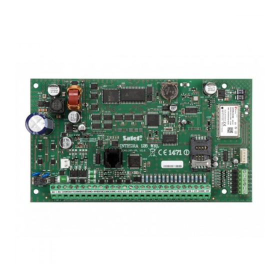
Page 14: Description Of The Mainboard
Installer Manual SATEL A 230 V AC power supply circuit with protective grounding must be available at the control panel installation place. 5.4.1 Description of the mainboard Description of terminals: - power supply inputs (18 V AC) - common ground OUT1...OUT2 - programmable high-current outputs (if output is not used, the 2.2 kΩ... - Page 15 SATEL INTEGRA 128-WRL...
-
Page 16: Connecting Devices To The Keypad Bus
Installer Manual SATEL GSM STATUS LED indicating the communicator and cellular network status: − OFF – the communicator disabled, − ON – outgoing voice call, − lit, getting dimmed every 0.5 second – incoming voice call, − flashing slowly – CSD communication, −... -
Page 17: Addressing Devices Connected To The Keypad Bus
SATEL INTEGRA 128-WRL Supply voltage measured at the LCD keypad terminals, with the display and key backlight on, must not be lower than 11 V. The Table 1 shows the number of wires required for correct connection of the device to the keypad bus if conductors with 0.5 mm diameter are used. -
Page 18: Numeration Of Keypad Zones
Installer Manual SATEL Programming keypad address without entering the service mode This method of address programming is particularly useful when – due to repeating addresses – the keypad support has been disabled and entering the service mode is impossible. 1. Disconnect the keypad power supply (KPD) and the CKM and DTM signal wires. -
Page 19: Connecting Devices To The Expander Bus
SATEL INTEGRA 128-WRL Fig. 5. Computer connection to the keypad RS-232 port. Shown on the right is the keypad interface. Shown on the left is the DB-9 female connector from soldering points side. Activate the C RS option in keypads to which the computer with OMMUNICATION GUARDX program is connected. -
Page 20: Connecting The Int-Vg Or Int-Av Module Or Ca-64 Sm Expander
Installer Manual SATEL another source of power must be provided for the module (a power supply unit or an expander with power supply). Fig. 7. Connection of modules with power supply. The Table 3 shows the number of wires required for correct connection of the device to the expander bus if conductors with 0.5 mm diameter are used. -
Page 21: End-Of-Line Resistors
SATEL INTEGRA 128-WRL NO – the wiring type dedicated to connecting devices with the NO (normally open) alarm output. Closing the circuit will trigger an alarm. EOL – this wiring type may be used to connect devices having the NC or NO alarm output. -
Page 22: Connecting The Sirens
Installer Manual SATEL Connecting the sirens Ω If high-current output is not used, the 2.2 k resistor should be connected between the output and common terminals. Fig. 9. The way of connecting sirens. I – siren without own power supply – alarm signaling triggered by high-current outputs. -
Page 23: Backup Power Supply
SATEL INTEGRA 128-WRL system should be instructed on how to disconnect the transformer from the mains (e.g. by indicating the fuse which protects the control panel supply circuit). 5.9.2 Backup power supply A 12 V lead-acid sealed battery should be connected to the control panel as a backup power source. -
Page 24: Emergency Procedure Of The Control Panel Start-Up
Installer Manual SATEL The control panel with factory settings supports all keypads connected to the bus, irrespective of the addresses set in them. However, it does not allow you to program the system. You will be able to start programming after carrying out the following operations: 1. -
Page 25: Gsm Communicator Start-Up
SATEL INTEGRA 128-WRL 10. After a prompt appears on the keypad display whether to save the data to the FLASH memory, press the key with the number 1. By saving a copy of the settings to the FLASH memory, the control panel will be able to restore them from a backup copy if an error is detected in the data stored in the RAM memory. -
Page 26: Installation Of Wireless Devices
Installer Manual SATEL T GSM IMEI/ The user function GSM IMEI/ . ([C .) makes it possible to ESTS check the level of signal received by the antenna, individual telephone identification number and telephone version. If the signal level is equal to 0, GSM/GPRS communication is impossible. -
Page 27: Adding New Wireless Devices
SATEL INTEGRA 128-WRL zones outputs list of devices device device APD-100 detector 17 APD-100 detector 17 unused/unavailable APD-100 detector 18 APD-100 detector 18 unused/unavailable AMD-100 detector 19 AMD-100 detector 19 unused/unavailable AMD-100 detector 20 AMD-100 detector 20 unused/unavailable AMD-101 detector... - Page 28 Installer Manual SATEL For some wireless devices, you can select whether the device will take up one or two positions (channels) on the list of devices. If you select one position for the ABAX device: − AMD-101 – only additional NC input will be supported, −...
-
Page 29: Removing Wireless Devices
SATEL INTEGRA 128-WRL 5. A message will confirm that the device has been added (unless you have entered an invalid serial number, of which the message will inform you). 5.1. Device type will be displayed. 5.2. A new name of the zone to which the device is to be assigned will be displayed. You can change the name. -
Page 30: Connecting The External Modem
Installer Manual SATEL Fig. 11. Computer connection to control panel RS-232 port. Shown on the left is RJ plug to be connected into the control panel mainboard socket. Shown on the right is DB-9 female plug (solder side view). A ready cable is offered in the DB9F/RJ-KPL set. -
Page 31: Configuring Settings Of The Modem To Be Connected To Control Panel
Fig. 13. Connection of the RS-232 ports of control panel and external modem with the PIN5 socket (the SATEL made ETHM-1 / ETHM-1 Plus / INT-GSM / INT-GSM LTE and GSM modules are connected in a similar way). Shown on the left is RJ plug to be connected into the control panel mainboard socket. -
Page 32: Connecting The Printer
Installer Manual SATEL Fig. 14. Proper setting of the external modem parameters. 5.16 Connecting the printer The control panel RS-232 port makes it possible to connect a printer provided with serial port. The control panel may print events in a “compressed" format (single event is printed in a single line containing up to 80 characters) or “extended”... -
Page 33: Numeration Of Zones And Outputs In The System
• the hardwired zones and outputs on the control panel board are numbered from 1 to 8. • numbers of the wireless zones and outputs supported by the INTEGRA 128-WRL control panel mainboard are set during the procedure of adding wireless devices – free and available numbers are assigned. -
Page 34: Replacing The Battery On Control Panel Mainboard
Installer Manual SATEL expander). The changes in numeration will only be valid until you start the expander identification function again. 7. Replacing the battery on control panel mainboard It is recommended that the status of clock and RAM memory backup battery be checked e.g. -
Page 35: Int-Klcd Keypad
SATEL INTEGRA 128-WRL Hardwired programmable outputs .................... 8 Maximum number of programmable outputs ............... 128 Power supply outputs ......................3 Communication buses ......................1+1 Keypads .......................... up to 8 Expansion modules ...................... up to 32 Objects (subsystems) ......................8 Partitions ..........................32 Telephone numbers for messaging .................. -
Page 36: Int-Klcds Keypad
Installer Manual SATEL Maximum current consumption ..................147 mA Environmental class according to EN50130-5 ................. II Operating temperature range ................. -10…+55 °C Maximum humidity ......................93±3% Enclosure dimensions ................. 145 x 115 x 26 mm Weight ..........................217 g 8.5 INT-KLCDS keypad Supply voltage .................... - Page 37 SATEL INTEGRA 128-WRL • Information on the capability to report events by means of GPRS using the 2013-12 1.12 UDP protocol has been added (p. 4). • Information on the INT-TSI keypad has been added (p. 5). • Information on the INT-KLFR keypad has been added (p. 5 and 34).
Need help?
Do you have a question about the INTEGRA 128-WRL and is the answer not in the manual?
Questions and answers