Satel INTEGRA 128-WRL Installer Manual
Alarm control panel
Hide thumbs
Also See for INTEGRA 128-WRL:
- Programming manual (95 pages) ,
- Installer manual (37 pages) ,
- Manual (117 pages)
Table of Contents
Advertisement
Quick Links
Download this manual
See also:
Programming Manual
Advertisement
Table of Contents

Subscribe to Our Youtube Channel
Related Manuals for Satel INTEGRA 128-WRL


Summary of Contents for Satel INTEGRA 128-WRL
- Page 1 INSTALLER MANUAL 1471 GDAŃSK integra-wrl_i_en 08/09...
- Page 2 Gdańsk, Polska 2008-11-10 Michał Konarski The list of countries where the INTEGRA 128-WRL has been approved for use – please see the website www.satel.pl The SATEL's goal is to continually upgrade the quality of our products, which may result in alterations of their technical specifications and firmware.
- Page 3 New functions of the INTEGRA 128-WRL control panels in version 1.07 Zones Option to use resistors of different values in 2EOL configuration. LCD keypad Keypad restart does not cause exit from the service mode. Wireless Support for new wireless devices: devices –...
-
Page 4: Table Of Contents
INTEGRA 128-WRL SATEL CONTENTS General description......................3 System specifications .......................3 Mainboard........................4 LCD keypads ......................5 Optional modules.......................5 2.3.1 Modules to be connected to keypad bus................ 5 2.3.2 Modules to be connected to expander bus ..............5 Wireless devices......................8 System installation ......................8 Installation plan......................9 Estimation of system current consumption ..............9... -
Page 5: General Description
SATEL Installer Manual 1. G ENERAL DESCRIPTION • Dedicated modern microprocessor-based construction for protection of medium-to-big-size facilities, with built-in GSM/GPRS industrial telephone and support for hardwired and wireless devices. • Two-way encrypted communication with ABAX system wireless devices on 868.0 MHz - 868.6 MHz frequency band. -
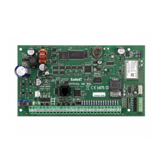
Page 6: Mainboard
INTEGRA 128-WRL SATEL – web browser (optionally, with ETHM-1 module connected), – mobile phone with MobileKPD application installed (optionally, with ETHM-1 module connected), – palmtop (PDA or MDA) with suitable application installed (optionally, with ETHM-1 module connected). • Variety of means for security system control: –... -
Page 7: Lcd Keypads
UARD installed, similarly as to LCD keypad, monitor events by using a special external device, and operate the control panel by means of software other than that offered by SATEL. 2.3.2 Modules to be connected to expander bus CA-64 E. Zone expander. Enables system expansion by 8 zones with support for NO, NC, EOL and 2EOL configurations. - Page 8 Additionally, the CA-64 EPSi expander zones offer support for vibration / roller shutter detectors. CA-64 ADR. Addressable zone expander. Enables system expansion by 48 zones. Equipped with a 2.2 A built-in switching mode power supply. The INTEGRA 128-WRL control panel supports the addressable zone expanders with firmware version v1.5 or later.
- Page 9 SATEL Installer Manual CA-64 DR. Expander for "DALLAS" chip readers. Supports the DALLAS chip readers, enabling execution of the access control functions and operation of the electromagnetic door lock. Enables control of the partition status by means of DALLAS chips.
-
Page 10: Wireless Devices
INTEGRA 128-WRL SATEL ACU-100. Controller of ABAX wireless system. Enables expansion of the system by additional wireless devices. INT-RX. 433 MHz key fob control expander. Enables remote key fobs to be assigned to the users in order to operate the system. -
Page 11: Installation Plan
SATEL Installer Manual NSTALLATION PLAN Installation must be preceded by preparation of a plan of the security alarm system. It is advisable that you draw up a sketch of the premises, showing all the devices to be included in the system, i.e. the control panel, keypads, detectors, sirens, expansion modules, etc. - Page 12 X program (the cable for making connection RJ type socket on the LOAD UARD control panel mainboard and the DB9 socket on the computer is supplied by SATEL). Enables remote programming by means of D X program through Ethernet (TCP/IP) LOAD network, if the ETHM-1 module is connected.
- Page 13 SATEL Installer Manual...
-
Page 14: Connecting Keypads And Other Devices To Keypad Bus
INTEGRA 128-WRL SATEL Terminals: - power supply inputs (18 V AC) - common ground OUT1...OUT2 - programmable high-current outputs (if not used, they should be loaded with 2.2 kΩ resistors) +KPD - dedicated power supply output for devices connected to keypad bus (13.6...13.8 V DC) - Page 15 SATEL Installer Manual Notes: • The signal wires (CKM, DTM and COM) must be run in one cable! • The supply voltage measured across the LCD keypad terminal block with backlight on should not be less than 11 V DC.
-
Page 16: Addressing Devices Connected To Keypad Bus
INTEGRA 128-WRL SATEL INTEGRA 128-WRL INT-KLCD-GR/BL INT-KLCDR-GR/BL Fig. 6. Connection of LCD keypad. 3.5.1 Addressing devices connected to keypad bus Each keypad/device to be connected to keypad bus must have its own individual address from the 0 to 7 range (addresses must not repeat). It is recommended that consecutive addresses be assigned starting from 0. -
Page 17: Programming Keypad Address Without Entering Service Mode
SATEL Installer Manual 2. Start the function K EYPAD ADDRESSES TRUCTURE ARDWARE DENTIFICATION EYPAD ADDRESSES 3. The message shown in Figure 7 will appear on display of all keypads connected to the control panel. n=0...7, current address of the keypad Fig. -
Page 18: Keypad Rs-232 Port
INTEGRA 128-WRL SATEL Keypad address Zone number in security system Table 2. 3.5.3 Keypad RS-232 port The keypad RS-232 port makes it possible to connect the computer with G X program UARD installed. The G X program enables visualization of the protected facility on computer... - Page 19 600 – 1000 m Table 3. Note: Signal wires (DT, CK and COM) must be run in one cable! INTEGRA 128-WRL CA-64 E Fig. 10. Connection of modules without power supply unit, by the example of CA-64 E zone expander. The expander is mounted in the same housing as the control panel, hence the TMP terminal is shorted to the COM ground.
-
Page 20: Addressing Devices Connected To Expander Bus
INTEGRA 128-WRL SATEL expanders must be independently supplied (by means of a separate cable from the control panel, expander with power supply, or a power supply unit). Where the distance between the control panel and the modules exceeds 300 m, the modules without power supply unit should not be supplied from the control panel. -
Page 21: Connecting Hardwired Detectors
• Too high resistance of the cables connecting the module to the control panel (large distance, too small number of wires for a single signal) may result in the module being not recognized by the identification function. INTEGRA 128-WRL 300 - 600 m CA-64 E... - Page 22 INTEGRA 128-WRL SATEL • EOL (end of line resistor), • 2EOL/NC (double end of line resistor, NC type detector), • 2EOL/NO (double end of line resistor, NO type detector). The value of resistors used in EOL and 2EOL configurations is programmable within the range from 500 Ω...
- Page 23 The NO, NC detectors in 2EOL configuration are connected in the same way, it is only important to correctly indicate the type of detector connected the control panel (2EOL/NO or 2EOL/NC). INTEGRA 128-WRL COM 12V EOL/NO Fig. 15. Exemplary connection of NO type detector in EOL configuration to control panel.
-
Page 24: Connecting Sirens
INTEGRA 128-WRL SATEL INTEGRA 128-WRL COM 12V 2EOL/NC Fig. 17. Exemplary connection of NC type detector in 2EOL configuration to control panel (NO type detector should be connected in the same way). CA-64 E Z1 COM Z2 COM 12V 2EOL/NC Fig. - Page 25 2.2 k resistor). This will prevent alarm from being accidentally triggered when starting the control panel. INTEGRA 128-WRL SENS. TMP SP-4001 Fig. 19. Connection of siren without own power supply to high-current outputs (by the example of SP-4001).
-
Page 26: Connecting Voice Synthesizer
DDRESSING DEVICES CONNECTED TO EXPANDER BUS Instead of the CA-64 SM synthesizer, it is possible to install the SATEL made SM-2 synthesizer in the system. The SM-2 enables saving and playback of single voice messages. In order to install the SM-2 synthesizer in the system, just insert the plug to the dedicated socket on control panel mainboard. -
Page 27: Connecting Power Supply
SATEL Installer Manual Fig. 22. Printer connection by means of DB-9 male plug (solder side view). Fig. 23. Printer connection by means of 5-pin DIN plug (solder side view). 3.11 C ONNECTING POWER SUPPLY Before connecting power supply, make sure that all connection operations in the system are completed. -
Page 28: Power Supply Connection Procedure
INTEGRA 128-WRL SATEL The INTEGRA 128-WRL control panel must be supplied with 18 V (±10%) alternating voltage. Use the transformer secondary winding to supply the mainboard. It is recommended that at least 40 VA transformer be used. The transformer should be permanently connected to the 230 V AC mains. Thus, before you set about making the connections, make yourself familiar with the electric system in the facility. -
Page 29: Starting Gsm Telephone
SATEL Installer Manual 2. The control panel program checks the control panel data saved in the RAM memory (the memory has a battery backup). If no error is detected, the control panel will be started with current settings. If an error is detected in the data saved in RAM memory, the settings will be restored from FLASH memory. -
Page 30: Installation Of Wireless Devices
The ARF-100 tester, made by SATEL, is a useful device for checking the signal level. The level of signal received by the device / control panel must not be lower than 40%. If the radio signal level at the anticipated installation place is too low, another place should be selected for installation. - Page 31 8. The radio communication has been designed so as to make possible operation of several INTEGRA 128-WRL control panels and ACU-100 controllers when their operating ranges overlap. Synchronization with the already working wireless systems is always carried out when turning on the control panel /controller and after each operation of adding/removing the supported devices.
-
Page 32: Adding New Wireless Devices
INTEGRA 128-WRL SATEL zones outputs list of devices device device ASP-105 siren ASP-105 siren ASP-105 siren 10 ASP-105 siren 10 ASP-105 siren 11 unused/unavailable APD-100 detector 11 APD-100 detector 12 unused/unavailable APD-100 detector 12 APD-100 detector 13 unused/unavailable AMD-100 detector... -
Page 33: Removing Wireless Devices
SATEL Installer Manual − switch on the ARF-100 tester, − insert the ASW-100 E/ASW-100 F wireless controller into 230 V socket, − insert battery to the ASD-100 detectors, − violate (open) the tamper contact in case of the other devices. -
Page 34: Compliance With Clc/Ts 50131-3 Requirements
INTEGRA 128-WRL SATEL 4. C CLC/TS 50131-3 OMPLIANCE WITH REQUIREMENTS To meet the requirements of CLC/TS 50131-3, you must: • reserve two control panel zones for each detector provided with the antimasking function: a supervision zone, to register violations of the detector, and a technical one, to register triggering of the antimasking feature. -
Page 35: Int-Klcdr-Gr / Int-Klcdr-Bl Keypad
SATEL Installer Manual Weight..........................231 g INT-KLCDR-GR / INT-KLCDR-BL KEYPAD Supply voltage, rated ..................12 V DC ±15% Current consumption: minimum............55 mA average ............60 mA maximum............156 mA Environmental class according to EN50130-5 ................. II Working temperature range ................-10°C…+55°C Maximum humidity ......................93±3% Housing dimensions (width x height x depth)...........140x126x26 mm... -
Page 36: History Of The Manual Updates
An efficient security system does not prevent burglary, assault or fire from happening, however it diminishes the risk that such a situation will cause no alarm or notification. Therefore, the SATEL Company recommends that operation of the whole security system be regularly tested.
Need help?
Do you have a question about the INTEGRA 128-WRL and is the answer not in the manual?
Questions and answers