
Related Manuals for Satel Integra Plus Series


Summary of Contents for Satel Integra Plus Series
- Page 1 INSTALLER MANUAL SATEL sp. z o.o. ul. Schuberta 79 80-172 Gdańsk POLAND tel. + 48 58 320 94 00 info@satel.pl www.satel.eu integra_plus_i_en 12/13...
- Page 2 Changes, modifications or repairs not authorized by the manufacturer shall void your rights under the warranty. The SATEL's goal is to continually upgrade the quality of its products, which may result in alterations of their technical specifications and firmware. The current information on the introduced modifications is available on our website.
- Page 3 Changes made to the firmware version 1.12 Support for new keypads: Keypads INT-KLFR – LCD keypad with mechanical keys and built-in proximity card reader; INT-TSG – touchscreen keypad; INT-TSI – touchscreen keypad. Support for new modules: Expansion modules ...
-
Page 4: Table Of Contents
Installer Manual SATEL CONTENTS General ..........................3 Features..........................3 Keypads..........................5 Features of keypads with mechanical keys ...............6 Expansion modules......................6 Modules to be connected to the keypad bus .............6 Modules to be connected to the expander bus ............7 System installation ......................9 Installation plan......................9 Estimation of the system current consumption ............9... -
Page 5: General
SATEL INTEGRA Plus 1. General This manual applies to the control panels of the INTEGRA Plus series: – INTEGRA 64 Plus – INTEGRA 128 Plus – INTEGRA 256 Plus The manual also describes keypads compatible with the INTEGRA Plus control panels and other devices that may be included in the security alarm system. - Page 6 – text messages defined by the installer; – SMS messages with content related to the event description in the event log (after connecting the GSM module, manufactured by SATEL). Event log 5631 (INTEGRA 64 Plus), 22527 (INTEGRA 128 Plus) or 24575 (INTEGRA 256 Plus) events.
-
Page 7: Keypads
SATEL INTEGRA Plus Programming Local programming: – keypad; – computer with the D X program installed, connected to the control panel RS-232 or LOAD USB port. Remote programming: – computer with the D X program installed, communicating via the telephone network LOAD or via the Ethernet network (optionally, if the ETHM-1 module is connected);... -
Page 8: Features Of Keypads With Mechanical Keys
X program installed in the same way as to the LCD keypad, UARD report events through a special external device, or operate the control panel using software other than that offered by SATEL. Only INT-RS Plus interface is compatible with INTEGRA 256 Plus control panel. -
Page 9: Modules To Be Connected To The Expander Bus
INT-SZ / INT-SZK. Code lock. Enables performance of the access control functions. INT-R. Universal expander for card / chip readers. Supports the proximity card readers manufactured by SATEL, readers with WIEGAND 26 interface or DALLAS chip readers. Enables performance of the access control functions. - Page 10 Installer Manual SATEL...
-
Page 11: System Installation
SATEL INTEGRA Plus INT-VG. Voice module. Allows remote operation of the control panel from the telephone keypad (interactive voice menu). It can store 16 voice messages for telephone messaging. INT-VMG. Voice message generator. Plays back prerecorded messages when specified events occur in the system. -
Page 12: Installation Of Control Panel Mainboard
Installer Manual SATEL Select cross-section of the power supply wires so that the supply voltage drop between the power supply and the supplied device should not exceed 1 V as against the output voltage. In order to guarantee correct functioning of the system components it is important that resistance and capacitance of the signal wires be as low as possible. - Page 13 SATEL INTEGRA Plus...
-
Page 14: Connecting Devices To The Keypad Bus
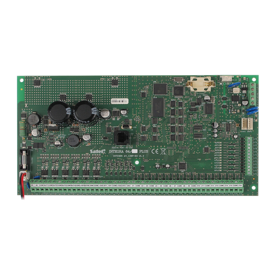
Installer Manual SATEL Explanations for Fig. 2: fuse for the battery charging circuit. battery connection cables (red +, black -). LEDs indicating the status of high-current outputs. BATTERY CHARGE LED indicator. LED indicating the status of + KPD power supply output. -
Page 15: Addressing Devices Connected To The Keypad Bus
SATEL INTEGRA Plus INTEGRA Plus INT-KLCD INT-KLCDR INT-KLCDS Fig. 3. Connection of keypads (other devices should be connected in a similar way). The Table 1 shows the number of wires required for correct connection of the device to the keypad bus if conductors with 0.5 mm diameter are used. -
Page 16: Numeration Of Keypad Zones
Installer Manual SATEL 2. Using the or keys, find the S item in the function list and press the ERVICE MODE or key. 3. Start the K . function ( S H I EYPADS ADDR... -
Page 17: Connecting Computer To The Keypad Rs-232 Port
SATEL INTEGRA Plus Zone number in the system Keypad INTEGRA 64 Plus INTEGRA 128 Plus INTEGRA 256 Plus address Table 2. 5.5.3 Connecting computer to the keypad RS-232 port In some keypads, the RS-232 port makes it possible to connect a computer with the G UARD program installed (see Fig. - Page 18 Installer Manual SATEL INTEGRA Plus CA-64 E CA-64 O Fig. 6. Connection of modules without power supply. INTEGRA Plus CA-64 EPS CA-64 ADR Fig. 7. Connection of modules with power supply. The Table 3 shows the number of wires required for correct connection of the device to the expander bus if conductors with 0.5 mm diameter are used.
-
Page 19: Connecting The Int-Vg Or Int-Av Module Or Ca-64 Sm Expander
SATEL INTEGRA Plus 5.6.1 Connecting the INT-VG or INT-AV module or CA-64 SM expander When connecting the INT-VG voice module, INT-AV audio alarm verification module or the CA-64 SM voice synthesizer expander, the CLK and DTA wires only are to be connected to the bus. -
Page 20: End-Of-Line Resistors
Installer Manual SATEL EOL/NC EOL/NO 2EOL/NC 2EOL/NO 3EOL/NC 3EOL/NO Fig. 8. The ways to connect detectors to zones. The detector outputs are designated with letters: A - alarm, T – tamper, M – anti-masking. R=R1+R2. 5.7.1 End-of-line resistors The value of R1, R2 and R3 EOL resistors is programmable within the range from 500 to 15 k ... -
Page 21: Connecting The Telephone Line
SATEL INTEGRA Plus Fig. 9. The way of connecting sirens. I – siren without own power supply – alarm signaling triggered by high-current outputs. II - siren with own power supply – alarm signaling triggered by low-current outputs, the high-current serving as power supply output. The value of resistors R is 2.2 k ... -
Page 22: Connecting Power Supply
Installer Manual SATEL For protection of the telephone dialer against voltage surges, the terminal should be connected to the 230 V AC network protective conductor (PE). Never connect the terminal to the neutral conductor (N). Fig. 10. Connection of the analog telephone line to the control panel. -
Page 23: Backup Power Supply
SATEL INTEGRA Plus 5.10.2 Backup power supply A 12 V lead-acid sealed battery should be connected to the control panel as a backup power source. The battery capacity must be adequately selected to match current consumption in the system. According to EN 50131 Grade 3, the battery must ensure operation of the system without mains supply for 30 hours, when the reporting is enabled in the control panel. -
Page 24: Emergency Procedure Of The Control Panel Start-Up
Installer Manual SATEL 2. Identification by the control panel of devices connected to the keypad bus. The identification can be performed by means of: S S H – the keypad ERVICE CODE ERVICE MODE TRUCTURE ARDWARE I ... -
Page 25: Connecting Computer To The Control Panel
SATEL INTEGRA Plus memory, the control panel will be able to restore them from a backup copy if an error is detected in the data stored in the RAM memory. 11. After the data are saved to the FLASH memory, the control panel will restart (the keypad display will be blank for a moment). - Page 26 Installer Manual SATEL Fig. 12. Diagram of external analog modem connection to the control panel. 6 43 Fig. 13. Connection of the RS-232 ports of control panel and modem with the DB-9 socket. Shown on the left is RJ plug to be connected into the control panel mainboard socket. Shown on the right is DB-9 male plug (solder side view).
-
Page 27: Configuring Settings Of The Modem To Be Connected To Control Panel
Shown on the left is RJ plug to be connected into the control panel mainboard socket. Shown on the right is PIN5 plug. A ready cable is offered by SATEL company (RJ/PIN5). 5.14.1 Configuring settings of the modem to be connected to control panel The MDM56 and MDM56 BO modems, manufactured by SATEL, do not require any configuration. -
Page 28: Connecting The Printer
Installer Manual SATEL Fig. 16. Proper setting of the external modem parameters. 5.15 Connecting the printer The control panel RS-232 port makes it possible to connect a printer provided with serial port. The control panel may print events in a “compressed" format (single event is printed in a single line containing up to 80 characters) or “extended"... -
Page 29: Numeration Of Zones And Outputs In The System
SATEL INTEGRA Plus Fig. 18. Connection of printer by means of DIN 5-pin plug (solder side view). Shown on the left is RJ plug to be connected into the control panel mainboard socket. 6. Numeration of zones and outputs in the system Numbers are automatically assigned to the zones and outputs: ... -
Page 30: Specifications
Installer Manual SATEL 7. Specifications Control panel INTEGRA 64 Plus INTEGRA 128 Plus INTEGRA 256 Plus Supply voltage 20 V AC ±15%, 50-60 Hz Recommended transformer 75 VA Standby current consumption from AC 135 mA mains Maximum current consumption from AC... -
Page 31: Int-Klcd Keypad
SATEL INTEGRA Plus INTEGRA 64 Plus INTEGRA 128 Plus INTEGRA 256 Plus EN50130-5 Operating temperature range -10…+55 °C Maximum humidity 93±3% Electronics board dimensions 264 x 134 mm Weight 320 g 7.2 INT-KLCD keypad Supply voltage ....................12 V DC ±15% Standby current consumption ..................17 mA... -
Page 32: Int-Klcdk Keypad
Installer Manual SATEL Enclosure dimensions ................114 x 94 x 23.5 mm Weight..........................141 g 7.6 INT-KLCDK keypad Supply voltage ....................12 V DC ±15% Standby current consumption ..................30 mA Maximum current consumption ..................110 mA Environmental class according to EN50130-5 .................II Operating temperature range.................
Need help?
Do you have a question about the Integra Plus Series and is the answer not in the manual?
Questions and answers