Inta HIPER II Installation And Operating Manual
Twin plate heat interface unit
Hide thumbs
Also See for HIPER II:
- Installation and operating manual (29 pages) ,
- Installation and operation manual (37 pages)
Table of Contents
Advertisement
Installation and Operating Manual
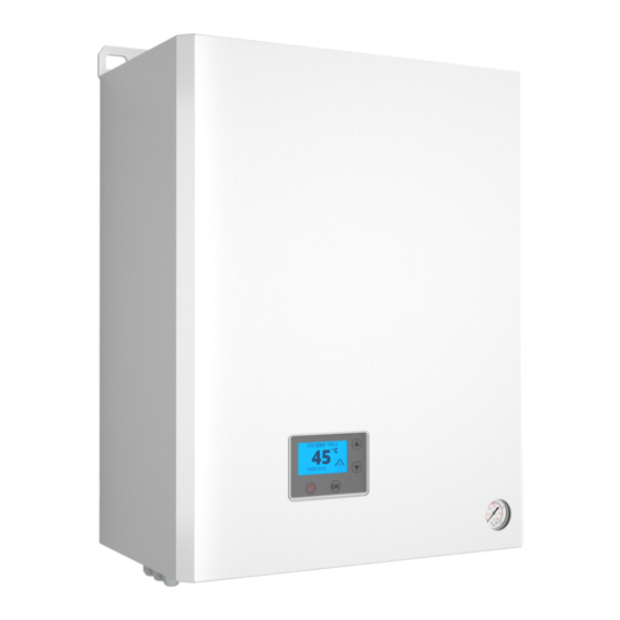
Twin Plate Heat Interface Unit
Instantaneous priority hot water and heating
In this document Inta have endeavoured to make all the information
and procedures accurate. Inta cannot accept responsibility should it
be found that in any respect the information is inaccurate or
incomplete as a result of future developments.
Rev 8
06/21 E&OE
Advertisement
Table of Contents

Related Manuals for Inta HIPER II


Summary of Contents for Inta HIPER II
- Page 1 Twin Plate Heat Interface Unit Instantaneous priority hot water and heating In this document Inta have endeavoured to make all the information and procedures accurate. Inta cannot accept responsibility should it be found that in any respect the information is inaccurate or incomplete as a result of future developments.
- Page 2 SECTION 1 - Important information and introduction These instructions describe the installation and operation and fault finding diagnostics of the Hiper II Heat Interface Unit (HIU). For operation of the entire plant, the technical documentation of all the components used such as, boiler, tank, pumps, pipework and valves must be complied with.
-
Page 3: Section 2 - Dimensions And Components
SECTION 2 - Dimensions and components Hiper II Heat Interface Units Code Hiper II Twin Plate HIU SZ 80kW DHW, 3 - 30 HTG HIPER2TP1580 Hiper II Twin Plate HIU 15-80kW DHW, 3 - 30 HTG ZENNER HEAT METER HIPER2TP1580ZE Dimensions 585 mm Height... - Page 4 Page 4 SECTION 3 - Components and schematic Schematic Hiper II HIU Safety valve discharge pipe CH Return Filling Group DH Return CH Flow Cold Supply DH Flow DHW Supply Drain valve / CH Circulating Pressure gauge air venting Pump...
- Page 5 Page 5 SECTION 3 - Components and schematic View from above View from underneath 1. Drain / air venting 2. Strainer with drain valves 3. Pocket for heat meter strainer 4. Isolation Valves 5. Diverter valve actuator 6. Pressure independent control valve & actuator 7.
-
Page 6: Section 4 - Accessories
Page 6 SECTION 4 - Accessories HIACPFFKIT Primary only first fix kit. Order with the HIU but supplied separately for use with the HIU first fix JIG. Pair stand off wall brackets. HIAC01SOBPACK First Fix Jig HI2ACJIG Using the Jig allows pipe work to be installed with- out the HIU and saves the cost of the purchase of a ‘first fix rail’... -
Page 7: Section 5 - Installation
Page 7 SECTION 5 - Installation 5.1 Before installation read and comply with the following Comply with all safety provisions. Do not tamper with the earthing connections as indicated on the casing. To secure the casing when closing the cover, use the provided M4 screw and washer provided to ensure earth continuity on the casing. - Page 8 Page 8 SECTION 5 - Installation Ensure the chosen installation site is inside the building, weather proofed and provides good access for maintenance, minimum requirements as on page 3. Note where and which pipe connections will be required, and pay attention to where the safety valve discharge pipe will terminate, and ensure this meets all current building regulations and has a continuous fall.
-
Page 9: Discharge Connection
Page 9 SECTION 5 - Installation For filling the Heating Circuit for the radiators or UFH, the filling valves and connecting pipes are integral to the HIU. This may be removed while pipe work and isolation valves are made good. Refit when commissioning. On completion of filling the Heating Circuit the temporary connection pipe between cold Water supply should be removed. - Page 10 Page 10 SECTION 5 - Installation 5.12 Accessory option - pre-formed pipes All connections from above Also available are time saving pipes which are formed to run behind the HIU and make all the connections from above. The isolation valve kit that can be used for this are 3/4” MxM union nuts, and seal with fibre washers, and can be fitted either below or above the HIU.
- Page 11 Page 11 SECTION 5 - Installation 5.14 Flushing Bypass Kits - i nstructions for KIT A • See section 6, HIU wiring complete. HIU turned off to close the PICV. • All HIUs on this circuit must be flushed using this method at the same time. •...
-
Page 12: Section 6 - Electrical Connections
Page 12 SECTION 6 - Electrical connections 6.1 Before electrical connection read and comply with the following. Comply with all safety provisions. Installation should only be carried out by a competent electrical installer and the installation conform to all IEE regulations Note that the Room thermostat switching must be VOLT FREE !! Note that the billing connection for pre-payment function must be VOLT FREE !! Isolate all electrical supplies before removing the access panel ! -
Page 13: Operation
Page 13 Section 7 - sequence of first power up menu. This is a ‘one off’ start up sequence to ensure the selection of radiators or UFH . On first power up, the controller will perform a check on all connected components. If all is OK, it will automatically proceed to the set up menu. - Page 14 HIU to not operate as efficiently as commissioned. Refer to the Installer Controller Parameter Settings Guide, available from Inta or the supplier request.
- Page 15 OPTION for a system with a hot water storage cylinder Set ∆T for loading the cylinder. This document is available on request from your Inta Specification OPTION for a system with a hot water storage cylinder manager involved with this installation project.
- Page 16 Page 16 SECTION 7 - The HIU Controller first power up and set up SECTION 10 - Fault and Error Codes / Fault finding guide Diagnostics - Fault code definitions. When a fault occurs the relevant code will be displayed on the controller screen. Fault codes inform that the controller has diagnosed a fault in one of the HIU’s components.
- Page 17 Page 17 SECTION 7 - The HIU Controller first power up and set up SECTION 10 - Fault and Error Codes / Fault finding guide Diagnostics - Error code definitions. When an error code is seen, the controller is warning of unsuitable operating conditions that may be causing the HIU to operate inefficiently or possibly not at all.
-
Page 18: Troubleshooting Checklist
Page 18 SECTION 7 - The HIU Controller first power up and set up SECTION 10 - Fault and Error Codes / Fault finding Guide Performance issues where no fault code is displayed REPORTED ISSUES Trouble Shooting Checklist • The water from the hot taps is COLD. Is there power to the HIU? •... - Page 19 Page 19 SECTION 7 - The HIU Controller first power up and set up SECTION 10 - Fault and Error Codes / Fault finding guide * Have the ‘Controller Programming Guide at hand! NO HOT WATER Is a warning symbol displayed (but heating is working) on the controller screen? See fault code description* and...
- Page 20 Page 20 SECTION 7 - The HIU Controller first power up and set up SECTION 10 - Fault and Error Codes / Fault finding guide * Have the ‘Controller Programming Guide at hand! NO HEATING Is a warning symbol displayed on the controller screen? See fault code description and check if the NO fault code displayed...
- Page 21 Page 21 SECTION 7 - The HIU Controller first power up and set up SECTION 10 - Fault and Error Codes / Fault finding guide NO POWER? Is there power to the fused spur connecting to the HIU? Turn off the potential power Check power supply and supply using the isolation Fuse feeding to the HIU.
- Page 22 Page 22 SECTION 7 - The HIU Controller first power up and set up SECTION 11 - Pump. Pump operating and Fault LEDs SECTION 7 - The HIU Controller first power up and set up 06/21 E&OE...
-
Page 23: Section 12 - Technical Specification
Heat meter options Zenner C5 MID compliant 1.5 qp M /hr 110mm Filters 1) Primary 2) Htg 3) CW inlet 800 micron Wras approved shock arrester Inta - mechanical spring loaded Internal pipework copper Technical DH maximum pressure 16 bar DH maximum temperature 85°... - Page 24 Page 24 SECTION 7 - The HIU Controller first power up and set up SECTION 13 - Spares View A View B View Front line spares description Part Code HI29337005 Grundfos UPM3 Pump - Head and Block inc automatic air vent HI29314005 Honeywell VC series DIVERTER ACTUATOR Honeywell DIVERTER CARTRIDGE M35X1,5...
- Page 25 Page 25 SECTION 7 - The HIU Controller first power up and set up SECTION 13 - Spares View C Heating Group View Ref Part Code Heating Group - assembled HI29332003 HEATING MANIFOLD BODY HI29332004 ELASTIC RING Ø28,2X2 HI24580005 1" NUT HI27494014 3BAR FAST CONNECTION SAFETY RELIEF VALVE HI23520040 L=41 STRAINER 800 MICRON ***...
- Page 26 Page 26 SECTION 7 - The HIU Controller first power up and set up SECTION 13 - Spares View F PHE Block Return Group Part Code View Ref PHE Block Primary Return Group - assembled HI29310003 PHE Primary return body HI29310004 O-RING Ø26,70X1,78 HI25022045...
-
Page 27: Section 14 - Warranty
Page 27 SECTION 7 - The HIU Controller first power up and set up SECTION 14 - Warranty Extended Product Warranty Intatec Limited (company number 04359938) (we, us, our) offers any business customer which 2. The Warranty only applies to any Hiper HIU bought in and installed and used in the United has purchased directly from us (Buyer/you) any of those products which are part of our Hiper Kingdom and Republic of Ireland. - Page 28 Twin Plate Heat Interface Unit Instantaneous priority hot water and heating Heat Interface Units (HIU) deliver heat generated from a centralised heating plant to multiple homes, apartments or flats. Heat from the main boiler plant is transferred to the home by two plate heat exchangers. One plate heat exchanger (PHE) provides the hot water supply (DHWS) and the other plate heat exchanger supplies the central heating circuit (CH).
Need help?
Do you have a question about the HIPER II and is the answer not in the manual?
Questions and answers