Bartscher 700 Series Instructions For Installation, Use And Maintenance Manual
Hide thumbs
Also See for 700 Series:
- Installation, use and maintenance manual (74 pages) ,
- Original instruction manual (18 pages) ,
- Instructions for installation, use and maintenance manual (14 pages)
Table of Contents
Advertisement
Quick Links
Advertisement
Table of Contents

Subscribe to Our Youtube Channel
Related Manuals for Bartscher 700 Series


Summary of Contents for Bartscher 700 Series
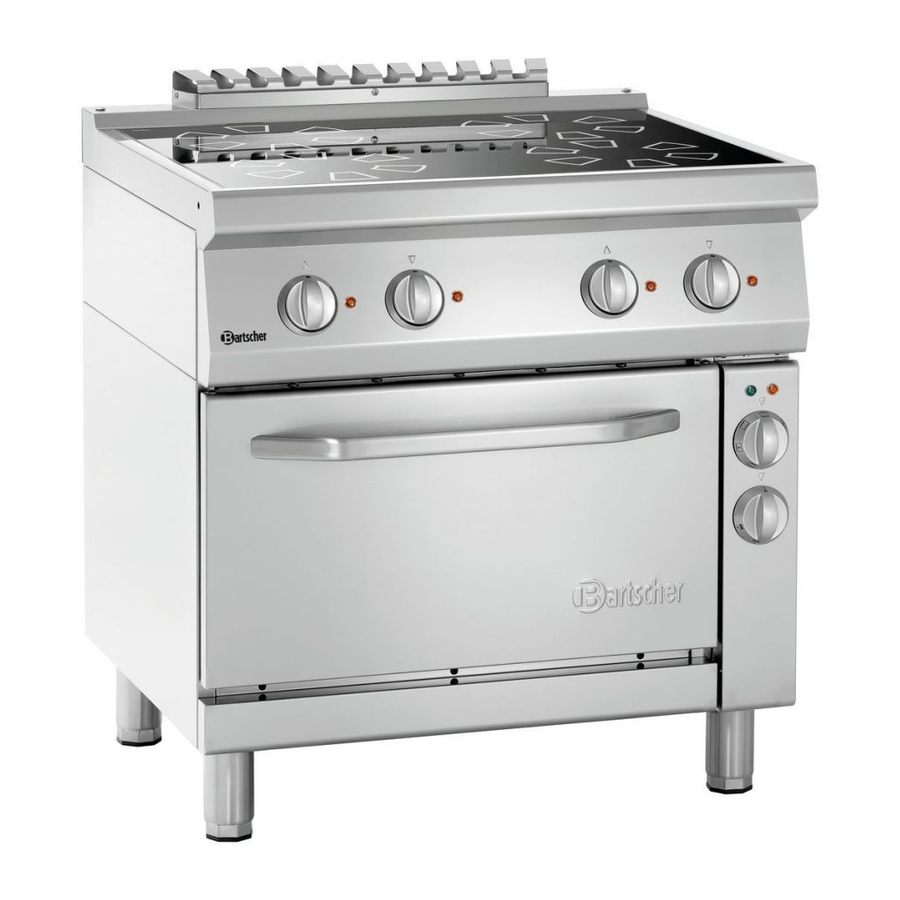
- Page 1 INSTALLATION, USE AND MAINTENANCE Gas Bratt Pans Serie 700 2856031 2856811...
- Page 2 Cooking equipment Series 700 Data Plate & Table of gas types p. 2 General Warnings p. 19 Normes et Directives p. 19 Installation and Gas & Electric connection p. 20 General Warnings for the Gas Bratt Pans p. 180 + 199 Maintenance p.
- Page 3 TYPENSCHILD \ PLAQUES DES CARACTERISTIQUES TECHNIQUES \ DATA PLATE TAFEL GASART \ TABLE TYPES DES GAZ \ TABLE TYPES OF Type gaz/ Type of gas/ [mbar] [mbar] [mbar] Gasart G20 (Methane) (2H) G25 (Methane) (2ELL) G25 (Methane) (2E+) G25.1 (Methane) (2HS) G25.3 (Methane) (2EK) G30 (Butane) (3B/P) 28-30...
- Page 4 GENERAL WARNINGS Read the instructions carefully before installation, use and maintenance of the appliance. The installation has to be performed by qualified personnel following the manufacturer’s instructions given in the provided manual. The appliance is only suitable for the preparation and cooking of food in industrial kitchens such as those used in restaurants, hospitals, company canteens, cooking centres, butcher’s shops and food production firms.
-
Page 5: Technical Features
TECHNICAL FEATURES The following instructions for set up and functioning refer to gas and mixed appliances belonging to categories I , II , II , with a power pressure for Butane/Propane 3B/P HS3B/P, 2E3PB/P 2H3+ 2H3B/P (G30-G31) of 30/50 mbar and Methane (G20) of 20 mbar. The DATA PLATE showing all the appliance information is to be found inside the right or left side of the control panel, depending on the model. - Page 6 Installation operations, gas or voltage conversions to other than the original, starting up the installation or appliance, ventilation, letting out fumes, and maintenance have to be done by qualified personnel following the manufacturer's instructions, observing the norms in force and in compliance with the following provisions (GB): ...
-
Page 7: Installation
Connection to a chimney with forced pull, putting in a pull device, letting out the products of combustion directly into the external environment. The energy supply to the appliance must be controlled by the system of forced evacuation and must be interrupted if its capacity falls below the values prescribed by the norms in force. - Page 8 agent or similarly qualified persons in order to avoid a hazard. As in international provisions, before setting up the appliance a unipolar device has to be installed with a contact opening of at least 3 mm that must not interrupt the YELLOW-GREEN earthing wire. This device has to be installed near the appliance, has to be approved, and has to have adequate capacity for the absorption of the appliance (see table TECHNICAL FEATURES).
-
Page 9: Maintenance
it to the pressure gauge pipe. Open the appliance gas supply valve, check the pressure output, and close the valve. Remove the pressure gauge pipe and screw the screws correctly into the pressure outlet. The pressure valve has to be within the minimum and maximum values shown in the table TYPES OF GAS. - Page 10 Clean the evacuation pipes of type "B" appliances, following the prescriptions in force in the country of installation; The gas tap should be lubricated, but this operation is quite difficult and its results are not very reliable. Therefore, it is advisable to substitute the gas tap 25/208...
- Page 11 GAS BRATT PANS SERIES 700 Technical features p. 181 Burners Features p. 182 Dimensions p. 185 Description of appliances p. 199 Regulation using a different type of gas p. 199 Substituting components p. 201 Operating anomalies p. 201 Instructions for Use p. 202 Device care and cleaning p.
- Page 12 TECHNISCHE DATEN CARACTERISTIQUES TECHNIQUES TECHNICAL FEATURES SERIE/SERIES/SERIE 700 Model Modèl 2856811 2856031 Model Masse [mm] 800x700x850 800x700x850 Dimensions Beckenabmessung Dimensions cuve [mm] 700x440x170 700x440x170 Tank Dimensions Beckeninhalt Capacité cuve 52.5 52.5 Tank capacity [KW] 12,5 12,5 Type [Kg/h] 0,986 0,986 (G30) Erdgas Methane...
- Page 13 CARACTÉRISTIQUES BRÛLEURS BURNER FEATURES BRENNEREINGESCHAFTEN (Tabella/Tableau/Table/Tafel/Tabla 75) (LV, PL - CAT. I Pilota/Veill Ø euse/Pilot/ Aria/Air/Luft Ugello/Gicleur/ Tipo gas/ Type gaz/ Gas Ø By-pass Zündflam /Aire “x” Injector/Düse/ Type/ Gasart [kW] [kW] [1/100 mm] Inyector [mm] Piloto [1/100 mm] [N°] BRUCIATORE/BRÛLEUR/BURNER/BRENNER/QUEMADOR Natural Methane gas 12,50...
- Page 14 (Tabella/Tableau/Table/Tafel/Tabla 79) I, PT, CH, GR, GB, IE, ES – CAT. ΙΙ 2H3+ Pilota/Veill Ø euse/Pilot/ Ugello/Gicleur/ Aria/Air/L Tipo gas/ Type gaz/ Gas Ø By-pass [1/100 Zündflamm MIN [kW] Injector/Düse/ uft/Aire Type/ Gasart [kW] “x” [mm] Inyector Piloto [1/100 mm] [N°] BRUCIATORE/BRÛLEUR/BURNER/BRENNER/QUEMADOR Natural Methan gas...
- Page 15 (Tabella/Tableau/Table/Tafel/Tabla 83) (FR, BE– CAT. ΙΙ 2E+3+ Ø gello/Gicleur/ Pilota/Veilleuse Aria/Air/Luf Tipo gas/ Type gaz/ Injector/Düse/ Ø By-pass /Pilot/Zündflam t/Aire “x” Gas Type/ Gasart [kW] [kW] Inyector [1/100 mm]] me/Piloto [mm] [1/100 mm] [N°] BRUCIATORE/BRÛLEUR/BURNER/BRENNER/QUEMADOR Natural Methan gas 12,50 AL190 x 2 27.2 (G20) Natural Methan gas...
- Page 16 (Tabella/Tableau/Table/Tafel/Tabla 87) (SE - CAT. III 1ab2H3B/P Ø Pilota/Veilleu Ugello/Gicleur/ se/Pilot/Zünd Aria/Air/Luf Tipo gas/ Type gaz/ Ø By-pass t/Aire “x” Injector/Düse/ flamme/ Gas Type/ Gasart [kW] [kW] [1/100 mm] Inyector Piloto [mm] [1/100 mm] [N°] BRUCIATORE/BRÛLEUR/BURNER/BRENNER/QUEMADOR ½ module Natural Methane Gas 12,50 AL190 x 2 27.2...
-
Page 17: Description Of Appliances
DESCRIPTION OF APPLIANCES Gas Bratt Pan Sturdy structure of stainless steel on four feet which make it possible to regulate the height. The outside finishing is of stainless steel. The cooking vat is provided with a thermostatic safety gas tap which enables the regulation of the temperature in a range from 90°C to 300°C inclusive. - Page 18 In order to replace the burner nozzle, remove the knobs (1) and the lifting crank (2); then remove front panel unscrewing the 4 screws that hold it in its place (4). Unscrew the connection (5) that joins the ramp (6) to the electro-valve (7) and the screws (8) that fix the electro-valve to the appliance frame.
- Page 19 SUBSTITUTING COMPONENTS ATTENTION! Before doing any kind of substitutions, make sure that the appliance is disconnected from the electric mains and that the gas cut off valve is closed. Safety valve In order to replace the safety valve, remove the water and gas knobs and the crank;...
- Page 20 Check that the flame of the pilot burner laps the thermocouple; if this is not the case, adjust the pilot The pilot burner lights off after burner through the regulating screw on the valve Press the gas knob in its correct position loosening the igniter knob ...
-
Page 21: Care And Maintenance Of The Appliance
Adjust to the required temperature by using the thermostat control knob (3). In order to switch off the main burner, turn the knob to the right into the ON position ; in order to switch off also the pilot burner, turn the knob again to the OFF position ... - Page 22 When cleaning, abrasive powders of any type, chlorine-based detergents and bleach should all be avoided. Also avoid pouring cold liquids on appliances while they are hot, or cracks could form which could cause the appliance to become deformed or broken. Stainless steel parts should not be exposed to prolonged contact with concentrated acid substances (e.g.
Need help?
Do you have a question about the 700 Series and is the answer not in the manual?
Questions and answers