Table of Contents
Advertisement
Quick Links
Advertisement
Table of Contents

Related Manuals for Bartscher 700FX-G180


Summary of Contents for Bartscher 700FX-G180
- Page 1 700FX-G180 / 700FX-G280 2839171 - 2839221...
- Page 2 Bartscher GmbH Phone: +49 5258 971-0 Franz-Kleine-Str. 28 Fax: +49 5258 971-120 Service hotline: +49 5258 971-197 D-33154 Salzkotten Germany www.bartscher.com 0085DL0223 Version: 1.0 Date of preparation: 2023-06-07...
-
Page 3: Table Of Contents
Original instruction manual Safety ......................2 Explanation of Signal Words ..............2 Safety instructions..................3 Residual Risks ..................6 Personal Protective Equipment ..............8 Intended Use ................... 9 Unintended Use ..................9 General information ..................10 Liability and Warranty ................10 Copyright Protection ................ -
Page 4: Safety
Safety Diese Bedi enungsanlei tung besc hrei bt di e Installation, Bedi enung und Wartung des Geräts und gilt als wic htige Infor mationsquelle und N achschl agewer k. Di e Kenntnis aller enthaltenen Sic herheits hinweis e und H andlungs anweisungen schafft die Vorauss etz ung für das sichere und s ac hger echte Ar beiten mit dem Gerät. D arüber hi naus müs sen die für den Ei ns atz ber eic h des Geräts geltenden ör tlichen Unfall verhütungs vorsc hriften und allgemeinen Sicherheits besti mmungen eing ehalten wer den. Dies e Bedi enungs anleitung is t Bes tandteil des Produkts und muss i n unmi ttelbarer N ähe des Ger äts für das In¬s tall ations-, Bedi enungs-, Wartungs- und R einigungspers onal jederzeit z ugänglich auf¬bewahrt werden. Wenn das Ger ät an eine dritte Pers on weiterg egeben wird, muss die Bedi enungsanlei tung mit ausgehändigt wer den. -
Page 5: Safety Instructions
Safety WARNING! The signal word WARNING warns against hazards that may lead to moderate or severe injuries or death if the hazards are not avoided. CAUTION! The signal word CAUTION warns against hazards that may lead to light or moderate injuries if the hazards are not avoided. , di e IMPORTANT! The signal word IMPORTANT indicates possible property damages,... - Page 6 Safety – do not produce sparks, do not actuate any electric switches, do not use phones (irrespective of it being landline phone or mobile phone); – do not operate any electric appliances in the vicinity of a gas supplied appliance; –...
- Page 7 Safety • Surfaces of the appliance become hot during operation. Burning hazard! High temperature remains for some time after switching the appliance off. • Do not touch any hot surfaces of the appliance. Use the provided handling elements and holders. •...
-
Page 8: Residual Risks
Safety Improper Use • Unintended or prohibited use may cause damage to the appliance. • The appliance may only be used when its technical condition is flawless and allows for safe operation. • The appliance may only be used when all connections are executed according to rules of law in force. - Page 9 Safety Residual Risks Dangerous situation Warning Chemicals Operator is dealing with Appropriate precautions chemicals (e.g. cleaners, should be taken. Always descaling agents, etc.) follow the instructions on the safety data sheets and labels for the products you use. Use personal protection measures recommended in the safety data sheets.
-
Page 10: Personal Protective Equipment
Safety Personal Protective Equipment Respiratory Safety Safety Hearing Head Gloves Eye protection tract clothing footwear protection protection protection Phase Transport Moving Unpacking Assembly Standard usage X (*) Settings Standard cleaning Special cleaning Maintenance X (*) Dismantling Disposal Personal protective equipment provided Personal protective equipment is available or must be used if required Personal protective equipment not provided... -
Page 11: Intended Use
Safety Intended Use As described below, every use of the appliance for a purpose differing and/or diverging from its intended standard use, is prohibited and considered to be an unintended use. The following is an intended use: – Deep fat frying of adequate food products. Unintended Use An unintended use may lead to personal injuries or property damages caused by hazardous voltage, fire or high temperature. -
Page 12: General Information
General information General information Liability and Warranty All information and instructions in this instruction manual account for legal regulations in force, current level of technical engineering knowledge as well as our expertise and experience, developed over the years. If special models or additional options are ordered, or state-of-the-art technical solutions were implemented, the actual scope of delivery of the appliance may, in some circumstances, differ from descriptions and numerous drawings in this instruction manual. -
Page 13: Transport, Packaging And Storage
Transport, Packaging and Storage Transport, Packaging and Storage Delivery Check Immediately upon reception, check the delivery for completeness and possible shipping damage. In the case of visible transport damage refuse to accept the appliance or accept it conditionally. Mark and note the scope of damage in shipping documents/consignment list of the shipping company and lodge a complaint. -
Page 14: Technical Data
Technical Data Technical Data Version / Characteristics • Type: table-top appliance • Supply type: gas • Gas type: – natural gas E – propane nozzles included • Ignition type: piezoelectric ignition • Material: Scotch-Brite polish • Basin with V-shaped bowl •... -
Page 15: Technical Specifications
Technical Data Technical Specifications Name: Deep fat fryer 700FX-G180 2839171 Art. No.: Material: CNS 18/10 Number of basins: Basin volume, in litres: Basin dimensions (W x D x H), in mm: 255 x 520 x 200 Number of baskets: Basket dimensions (W x D x H), in mm:... - Page 16 Technical Data Name: Deep fat fryer 700FX-G280 2839221 Art. No.: Material: CNS 18/10 Number of basins: Basin volume, in litres: Basin dimensions (W x D x H), in mm: 255 x 520 x 200 Number of baskets: Basket dimensions (W x D x H), in mm: 190 x 340 x 110 Basket filling capacity in kg: Temperature range, min.–max., in °C:...
- Page 17 Technical Data Gas Pressure Table Countries Appliance Connection pressure (mbar) categories pressure Rated Min. Max. (mbar) LU-PL I2EK G25.3 NO-NL-CY- I3B/P G30/G31 28-30 I3B/P G30/G31 G20/G25 20/25 25/30 BE-FR II2E+3+ G30/G31 28-30/37 20/25 35/45 II2ELL3B/P G30/G31 42.5 57.5 ES-GB-GR-IE- II2H3+ IT-PT-SK G30/G31 28-30/37...
- Page 18 Technical Data Countries Appliance Connection pressure (mbar) categories pressure Rated Min. Max. (mbar) DK-SE III1a2H3BP G30/G31 28-30 G110 IT-CH II1a2H G110 II2EK3B/P G25.3 G30/G31 28-30 Tab. 1 16 / 38 2839171...
- Page 19 Technical Data Nozzles and settings Countries Gas type Ref. Art. No. (mbar) 2839171 / 74GFRT 2839221 / 76GFRT AT-BE-BG-CH-CZ- DE-DK-EE-ES-FI- FR-GB-GR-HR-IE- A(mm) G20/ G25 20/25 IT-LT-LU-LV-NO-PL- PT-RO-SE-SI-SK-TR A(mm) G25.3 A(mm) A(mm) G25.1 A(mm) BE-BG-CY-CZ-DK- EE-ES-FI-FR-GB- 28-30 /37 G30/ G31 GR-HR-HU-IE-IT-LT- 28-30 A(mm) LU-LV-MT-NL-NO-...
- Page 20 Technical Data Countries Gas type Ref. Art. No. (mbar) 2839171 / 74GFRT 2839221 / 76GFRT G30/ G31 A(mm) G30/ G31 AT-CH-DE-HU A(mm) UM: MAX nozzle Um: MIN nozzle UP: Ignition burner A: Open the air ring Pa: Connection pressure Ventilation grill with 8 openings, Ø4.2 mm Tab.
- Page 21 Technical Data Gas Consumption Art. No. / Model 2839171 / 74GFRT 2839221 / 76GFRT Rated heat load, Qn 14,0 Rated heat load, Qn G25.3 6,65 13,3 (25) Total gas G20 (20) 0,74 1,48 consumption G25.3 (25) 0,80 1,60 G25 (20) 0,86 1,72 G20 (25)
-
Page 22: List Of Components Of The Appliance
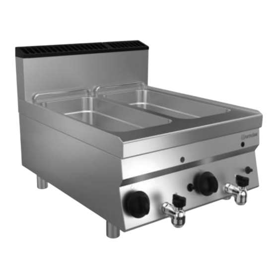
Technical Data List of Components of the Appliance 2839171 Fig. 1 2. Bracket for hanging the deep 1. Ventilation chimney frying basket 3. Basin 4. Housing 5. Piezoelectric igniter 6. Grease drain tap 7. Knob 8. Height-adjustable feet (4 pcs) 9. -
Page 23: Functions Of The Appliance
Technical Data 2839221 Fig. 2 2. Bracket for hanging the deep 1. Ventilation chimney frying basket (2 pcs) 3. Basin (2 pcs) 4. Housing 5. Burner sight glass (2 pcs) 6. Piezoelectric igniter (2 pcs) 7. Grease drain tap (2 pcs) 8. -
Page 24: Installation Instructions
Installation Instructions Installation Instructions Installation CAUTION! Incorrect installation, positioning, operation, maintenance or misuse of the appliance may lead to personal injury or property damage. Positioning and installation, as well as repairs may be performed by authorised technical service only and in compliance with the applicable national law. - Page 25 Installation Instructions Place of Installation • This appliance are A1 type appliances, which means that they do not have to be connected to a fume extraction system. In order to provide venting in the place of installation, follow indications included in DVGW G631 data sheet. •...
- Page 26 Installation Instructions – easily accessible; – well ventilated. • Never place the appliance directly next to walls, furniture, or other objects made of flammable materials. Maintain minimum clearance of 200 mm between side and rear walls and the said objects and walls. Maintain clearance of at least 600 mm between the appliance's surface and horizontal surfaces over the appliance.
-
Page 27: Gas Connection
Installation Instructions Gas Connection Connection to Gas Installation • Before making the connection to gas installation, make sure that the appliance is set to gas and pressure is available in the installation location (see rating plate on the appliance and packaging). If factory default settings are not suitable, the appliance must be adapted to the available gas type (section 'Resetting to Other Type of Gas / Required Adjustments'). - Page 28 Installation Instructions • Check the rated heat pressure with gas meter and a stop watch. Measure exactly the amount of gas flowing per unit of time the appliance is consuming with maximum power. • Compare the measured value with data on consumption in section 'Technical Specifications', Table 3.
- Page 29 Installation Instructions Replacement of Main Burner Nozzle Fig. 3 1. Remove the knob(s). 2. Unscrew front guard (operation panel) and remove it from the appliance. 3. Remove the nozzle handle ramp. 4. Loosen V bolt (Fig. 3). 5. Remove main burner's nozzle, UM (Fig. 3), and exchange it with a nozzle suitable for the new type of gas (part of the delivery).
- Page 30 Installation Instructions Exchange of Ignition Burner Nozzle 1. Remove the front guard / operation panel. 2. Screw out the R connection (Fig. 4). 3. Remove the UP nozzle and exchange it with a nozzle provided in Table 2 (part of the delivery). 4.
-
Page 31: Operating Instruction
Operating Instruction Operating Instruction • Setzen Sie di e Boden-Abdec kung in das Bec ken ei n. T he c over acts as a spac er between the heating element and l eft- over food tray. Ostrożni e osadzić s krz ynkę roz dzi elczą z elementem grzewcz ym na tylnej kr awędzi urz ądz enia. Sworz eń w dol nej częś ci s krz ynki r ozdzielcz ej musi wc hodzić w otwór w urządz eni u głównym. W taki s posób s krz ynka r oz dzielcz a j est pr awidł owo us tawi ona. WARNING! Fire hazard! Operation of the appliance with the oil level below MIN mark may lead to... - Page 32 Operating Instruction Before placing the lid, make sure that it is dry, so that no water drips into the tank. When pouring hot frying oil / fat in cubes (blocks) be aware of the risk of burns. Cool the frying oil / fat in cubes (blocks) before pouring. CAUTION! The deep fat fryer can only be used by individuals who have been instructed in the proper use of the appliance and hazards that may arise...
- Page 33 Operating Instruction Instructions for using frying oil or fat in cubes (blocks) • Always use oil suitable for frying (e.g. vegetable oil, sunflower oil, peanut oil, etc.) or fat in cubes/blocks only. NOTE! Melt (dissolve) the fat in cubes (blocks) beforehand in a separate dish! •...
- Page 34 Operating Instruction Control Panel 1. Knob 2. Switching ignition burner 3. OFF position (0) 4. Control range 1–7 Fig. 5 Settings The appliance (temperature) is controlled steplessly, using the knob. The knob features the following operating positions: – Switching off (0) –...
- Page 35 Operating Instruction WARNING! Do not use frying oil / fat in cubes (blocks) for an extended period of time in too low a temperature, as they cease to be suitable for use. In the case of longer interruptions between the frying processes, set the knob to lower value.
-
Page 36: Cleaning And Maintenance
Cleaning and Maintenance Exchange and removal of frying oil / liquid fat in cubes (blocks) 1. The frying oil / liquid fat in cubes (blocks) should be replaced regularly when it no longer fulfils legal requirements. 2. After cooling, the frying oil / fat in cubes (blocks) should be drained from the basin via fat drain tap into a suitable container. -
Page 37: Cleaning
Cleaning and Maintenance Cleaning 1. At the end of a working day, clean the appliance thoroughly. 2. Remove the deep frying basket from the basin. 3. Drain the cooled frying oil from the basin. NOTE! Observe instructions in section 'Exchange and Removal of Frying Oil / Liquid Fat in Cubes (Blocks)'. - Page 38 Cleaning and Maintenance Operate the appliance observing the instruction manual and indications in section 'Indications for the User' and check: – gas supply pressure (see next section). – correct switching of burners and operation of the fume extractor (chimney). Gas Supply Pressure Check Use a suitable manometer with 0.1 mbar minimum pitch.
-
Page 39: Possible Malfunctions
Possible Malfunctions Possible Malfunctions Mögliche The table below contains descriptions of possible causes and solutions to malfunctions or errors during operation of the appliance. When malfunction cannot be removed, contact the technical service. In such a case, provide article number, model name and serial number. These data may be found in the rating plate. -
Page 40: Disposal
Disposal Problem Possible Cause Solution Main burner does not Loss of pressure in gas Check gas supply switch on when the supply line ignition burner is on Clogged line or nozzles Contact the service company Damaged knob Contact the service company Main burner is damaged or Contact the service company gas outlet openings are...
Need help?
Do you have a question about the 700FX-G180 and is the answer not in the manual?
Questions and answers