Goodwe SBP Series User Manual
Ac-coupled
Hide thumbs
Also See for SBP Series:
- User manual (19 pages) ,
- Quick installation manual (112 pages) ,
- Quick start manual (9 pages)
Table of Contents
Advertisement
Advertisement
Table of Contents

Subscribe to Our Youtube Channel
Related Manuals for Goodwe SBP Series


Summary of Contents for Goodwe SBP Series
- Page 1 User Manual AC-Coupled Inverter SBP Series V1.5-2021-01-21...
-
Page 2: Table Of Contents
Content User Manual V1.5-2021-01-21 TABLE OF CONTENTS 01 Introduction .............. 1 1.1 Operation Modes Introduction ..............1 1.2 Safety and Warning ...................2 1.3 Product Overview ..................4 02 Installation Instructions ..........5 2.1 Unacceptable Installations ...............5 2.2 Packing List ....................5 2.3 Mounting ....................6 2.3.1 Select Mounting Location ................. - Page 3 User Manual V1.5-2021-01-21 Content 04 OTHER ..............22 4.1 Error Messages..................22 4.2 Troubleshooting ..................23 4.3 Disclaimer ....................27 4.4 Technical Parameters ................29 4.5 Quick Checklist To Avoid Dangerous Conditions .........33 Appendix ..............34...
-
Page 4: Introduction
01 Introduction User Manual V1.5-2021-01-21 01 Introduction S-BP series bi-directional inverter is designed for both indoor and outdoor use, which could be used with or without existing grid-tied inverter systems to store energy using batteries. Energy produced from grid-tied inverters shall be used to optimize self-consumption, excess energy will be used to charge the batteries, if the battery is already full, power excess power could be exported to the grid. -
Page 5: Safety And Warning
01 Introduction 1.2 Safety and Warning The SBP series of inverters from Jiangsu Goodwe Power Supply Technology Co.,Ltd (also called GoodWe) strictly complies with related safety rules for product design and testing. Please read and follow all of the instructions and cautions appearing on the inverter or in the User Manual during installation, operation and maintenance, as any improper operation might cause personal injury or property damage. - Page 6 01 Introduction User Manual V1.5-2021-01-21 Safety Warnings Any installation or operations on the inverter must be performed by qualified electricians in compliance with standards, wiring rules and the requirements of local grid authorities or companies (such as AS 4777 and AS/NZS 3000 in Australia). Prohibit inserting and pulling the AC and DC terminals when the inverter is running.
-
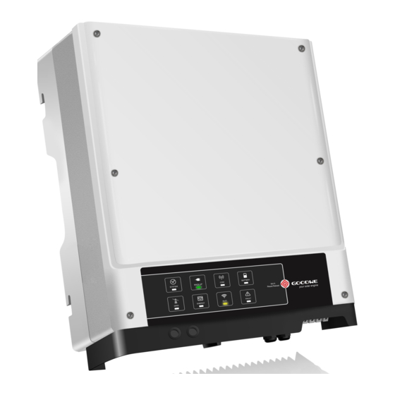
Page 7: Product Overview
User Manual V1.5-2021-01-21 01 Introduction 1.3 Product Overview... -
Page 8: Installation Instructions
01 Introduction User Manual V1.5-2021-01-21 02 Installation Instructions 2.1 Unacceptable Installations Please avoid the following installations which will damage the system or the Inverter. The following installations should be avoided. Any damage caused will not be covered by the warranty policy. SYSTEM BACK-UP BATTERY... -
Page 9: Mounting
User Manual V1.5-2021-01-21 02 Installation Instructions Battery Terminal PE Terminal Expansion Bolts Hexagon Head Screw Pan Head Screw Documentations 2.3 Mounting 2.3.1 Select Mounting Location For inverter's protection and convenient maintenance, mounting location for inverter should be selected carefully based on the following rules: Rule 1. -
Page 10: Mounting
02 Installation Instructions User Manual V1.5-2021-01-21 300mm Upward ---------- 300mm 200mm 200mm 300mm Downward ------ 500mm Front ------------- 300mm Both sides -------- 200mm SYSTEM BACK-UP BATTERY Wi-Fi Reset/Reload 2019 GRID ENERGY Wi-Fi FAULT 500mm Mounting Support Requirements • The mounting support shall be nonflammable and fireproof. •... - Page 11 User Manual V1.5-2021-01-21 02 Installation Instructions • Please use the mounting bracket as a template to drill 6 holes in right positions (10mm in diameter,and 80mm in depth). • Use expansion bolts in accessory box and fix the mounting bracket onto the wall tightly. Note: Bearing capacity of the wall must be higher than 25kg, otherwise it may not be able to keep inverter from dropping.
-
Page 12: Electrical Wiring Connection
02 Installation Instructions User Manual V1.5-2021-01-21 A lock could be used for anti-theft purposes if it is necessary for individual requirement. SYSTE M BACK -UP BATT ERY GRID Wi-Fi ENER GY Reset /Reloa Wi-Fi FAULT The lock is not included in the package, 1.2~2N·m It can be purchesed by user. - Page 13 6~8N·m * For the compatible lithium batteries (LG / PYLON / BYD / GCL / DYNESS / ALPHA) connection, please visit www.goodwe.com. Battery Protection Description Battery will act as protective charge/discharge current limitation under any condition as below: • Battery SOC is lower than I-DOD •...
-
Page 14: On-Grid & Back-Up Connection
02 Installation Instructions User Manual V1.5-2021-01-21 Note: 1. Under on-grid mode, battery is protected from over discharge by DOD and discharge voltage, under off-grid mode, it is protected by only discharge voltage in priority. 2. The DOD setting of a battery prevents the inverter from discharging battery reserve power. As soon as the DOD is reached the load of building will only be supported by either PV power or from the grid. - Page 15 In the case where the systems are not connected to the batteries, the back-up function is strongly not advised for use. GoodWe shall not cover the standard warranty and be liable for any consequences arising from users not following this instruction.
-
Page 16: Smart Meter & Ct Connections
02 Installation Instructions User Manual V1.5-2021-01-21 Special adjustable settings The inverter has field adjustable setting like tripping point, tripping time, reconnect time, active SYSTEM BACK-UP BATTERY and invalid QU/PU curves etc. They can be adjusted Wi-Fi Reset/Reload 20 19 GRID ENERGY Wi-Fi FAULT... - Page 17 Load Note: 1. Please use the Smart Meter with 3 CTs in GoodWe product box. 2. CT cable is 3m as default, could be extended to a max of 5m. 3. Smart Meter communication cable (RJ45) is attached on the inverter ("To Smart Meter" cable), could...
-
Page 18: Dred & Earth Fault Alarm
DRED is used for Australia and New Zealand installation (also used as remote shutdown function in European countries), in compliance with Australia and New Zealand safety requirements( or European countries). And DRED device is not provided by GoodWe. Detailed connection of DRED device is shown below: Screw this plate off from the inverter. -
Page 19: Earth Fault Alarm Connection
User Manual V1.5-2021-01-21 02 Installation Instructions 1. Plug out the 6-pin terminal and dismantle the resistor on it. 2. Plug the resistor out, leave the 6-pin terminal for next step. Note: The 6-pin terminal in the inverter serves the same function as DRED / Remote shutdown device. - Page 20 02 Installation Instructions User Manual V1.5-2021-01-21 Wiring System For S-BP Series hybrid inverter For 3-phase Smart Meter wiring connection, please refer to "3-phase Smart Meter & CT Connection Diagram". Inverters should not be installed in multiple phase combination. "To Battery" Cable[2] AC Breaker[4] Smart Meter...
- Page 21 User Manual V1.5-2021-01-21 02 Installation Instructions System connection diagrams Note: According to Australian safety requirements, the neutral cables of the on-grid side and backup side must be connected together. Otherwise, the backup function will not work. This diagram is an example for Australia, South Africa and New Zealand grid system. Distribution box Backup Loads...
-
Page 22: Manual Operation
03 MANUAL OPERATION User Manual V1.5-2021-01-21 03 MANUAL OPERATION 3.1 Wi-Fi Configuration This part shows the configuration using a web page. Wi-Fi configuration is absolutely necessary for online monitoring and maintenance. Preparation: 1. The inverter must be powered up with battery or grid power. 2. -
Page 23: Pv Master
Operation steps are the same for Android system and iOS system although the two interfaces are slightly different. For more detailed opertaion instructions, please refer to PV Master user manual in www.goodwe.com. PV Master App Note: For Australian customers please select from Australia Region A/B/C to comply with AS/NZS 4777.2:2020. -
Page 24: Cei Auto-Test Function
03 MANUAL OPERATION User Manual V1.5-2021-01-21 3.3 CEI Auto-Test Function The PV auto-test function of CEI is integrated into the PV Master App to satisfy Italian safety requirements. For detailed instructions regarding this function, please refer to "PV Master Operation Instructions". 3.4 Startup/shutdown Procedure 3.4.1 Startup Procedure Note: Before closing the AC breaker between the inverter and the grid, you need to use a... -
Page 25: Other
User Manual V1.5-2021-01-21 04 OTHER 04 OTHER 4.1 Error Messages. The error messages below will be displayed on PV Master App or reported by e-mail if an error occurs. ERROR EXPLANATION REASON SOLUTIONS MESSAGE Utility Loss Public grid power Inverter does 1. -
Page 26: Troubleshooting
04 OTHER User Manual V1.5-2021-01-21 Neutral & ground Check (use multi-meter) if there is cables are not high voltage (normally should be connected well on lower than 10V) between N & PE Relay Check Self checking of AC side or just an cable on the AC side. - Page 27 User Manual V1.5-2021-01-21 04 OTHER To Back-Up load To Public Grid 4.2-1 4.2-2 4.2-3 Battery Settings, BMS Communication and Safety Country: After connecting Solar-WiFi* (* means the last 8 characters of the inverter serial No.), check on PV Master APP Param to make sure battery type is right what you have installed, and Safety Country is right.
- Page 28 04 OTHER User Manual V1.5-2021-01-21 3. Load power is lower than 150W, as battery will only discharge if load power is higher than 150W. 4. Smart Meter communication fails or CT connected in a wrong direction, which gives S-BP wrong data. 5.
- Page 29 2. Battery SOC is too low, battery trips to protect itself. 3. An electrical short circuit occurred on battery connection side. Or other reasons please contact GoodWe for details. Q: Which battery should I use for S-BP? A: For S-BP inverters, it could connect lithium batteries, with nominal voltage 48V, max charge voltage 60V.
-
Page 30: Disclaimer
04 OTHER User Manual V1.5-2021-01-21 Other Questions Q: Is there a quick way to make the system work? A: The shortest way, please refer to S-BP QUICK INSTALLATION INSTRUCITONS. Q: What kind of load can I connect on Back-Up side? A: Please refer to user manual on page 11. - Page 31 User Manual V1.5-2021-01-21 04 OTHER Maintenance Maintaining Item Maintaining Method Maintaining Period Check the heat sink, air intake, and air System Clean Once 6-12 months outlet for foreign matter or dust. Turn the DC switch on and off ten DC Switch consecutive times to make sure that it is Once a year working properly.
-
Page 32: Technical Parameters
04 OTHER User Manual V1.5-2021-01-21 4.4 Technical Parameters Technical Data GW3600S-BP GW5000S-BP Battery Input Data Battery Type Li-Ion Li-Ion Rated Battery Voltage (V) Battery voltage range (V) 40~60 40~60 Max. Charging Voltage (V) ≤60 (Configurable) ≤60 (Configurable) Max. Charging Current (A) Max. - Page 33 User Manual V1.5-2021-01-21 04 OTHER Maximum output overcurrent protection (A) Output Power Factor ~1 (Adjustable from 0.8 leading to 0.8 lagging) Output THDi (@Nominal Output) <3% <3% Max. Output Fault Current(peak and 70A,3us 70A,3us duration) (A) AC Output Data (Back-up) Back-up Rated apparent power (VA) 3680 5000...
- Page 34 04 OTHER User Manual V1.5-2021-01-21 Operating Altitude (m) 4000 4000 Cooling Nature Convection Nature Convection Noise (dB) <25 <25 User Interface LED & APP LED & APP Communication with BMS RS485; CAN RS485; CAN Communication with Meter RS485 RS485 Communication with Portal Wi-Fi Wi-Fi Weight (kg)
- Page 35 User Manual V1.5-2021-01-21 04 OTHER EN 61000-6-1, EN 61000- EN 61000-6-1, EN 61000- 6-2, EN 61000-6-3, EN 6-2, EN 61000-6-3, EN 61000-6-4 61000-6-4 EN 61000-4-16, EN EN 61000-4-16, EN 61000-4-18, EN 61000- 61000-4-18, EN 61000- 4-29 4-29 *1: The actual charge and discharge current also depends on the battery. *2: Battery capacity could be not less than 100Ah where the back-up function is to be applied.
-
Page 36: Quick Checklist To Avoid Dangerous Conditions
04 OTHER User Manual V1.5-2021-01-21 4.5 Quick Checklist To Avoid Dangerous Conditions 1. Inverter cannot be installed near flammable, explosive or strong electro-magnetic equipment. 2. Remember that this inverter is heavy! Please be careful when lifting out from the package. 3. -
Page 37: Appendix
User Manual V1.5-2021-01-21 Appendix Appendix Protection category definition Moisture location category definition Level Moisture Parameters 4K4H Temperature Range 0~+40°C -33~+40°C ~20~+55°C Moisture Parameters 5%~85% 15%~100% 4%~100% Environment category definition Environment Condition Ambient Temperature Relative Humidity Applied to Outdoor -20~50°C 4%~100% Indoor Unconditioned -20~50°C 5%~95%... - Page 38 01 Introduction User Manual V1.5-2021-01-21 Pollution degree definition No pollution or only dry, non-conductive polllution occurs. The Pollution Degree I pollution has no influence. Normally only non-conductive pollution occurs. Occasionally, however, Pollution Degree II a temporary conductivity caused by condensation must be expected. Conductive pollution occurs, or dry.
- Page 39 JIANGSU GOODWE POWER SUPPLY TECHNOLOGY CO.,LTD No. 90 Zijin Rd., New District, Suzhou, 215011, China www.goodwe.com service@goodwe.com Local Contacts...
Need help?
Do you have a question about the SBP Series and is the answer not in the manual?
Questions and answers