Goodwe ES Series User Manual
Hybrid inverter
Hide thumbs
Also See for ES Series:
- User manual ,
- Quick installation manual (112 pages) ,
- Quick start manual (9 pages)

Related Manuals for Goodwe ES Series


Summary of Contents for Goodwe ES Series
- Page 1 User Manual Hybrid Inverter ES Series 3.0-6.0kW G2 AC-Coupled Inverter SBP Series 3.6-6.0kW G2 V1.0-2022-07-20...
- Page 2 Copyright Statement Trademarks and other GoodWe trademarks are trademarks of GoodWe Company. All other trademarks or registered trademarks mentioned in this manual are owned by GoodWe Technologies Co., Ltd. NOTICE The information in this user manual is subject to change due to product updates or other reasons.
-
Page 3: Table Of Contents
CONTENT User Manual V1.0-2022-07-20 CONTENT 1 About This Manual ���������������������������������������������������������������������������� 1 1.1 Applicable Model ........................1 1.2 Target Audience ........................1 1.3 Symbol Definition ........................1 1.4 Updates ............................1 2 Safety Precaution ����������������������������������������������������������������������������� 2 2.1 General Safety ..........................2 2.2 PV String Safety ........................2 2.3 Inverter Safety ..........................3 2.4 Battery .............................4 2.5 Personnel Requirements ......................4... - Page 4 9.2 Removing the Inverter ......................44 9.3 Disposing of the Inverter ....................... 44 9.4 Troubleshooting ........................45 9.5 Routine Maintenance ......................54 10 Technical Parameters ��������������������������������������������������������������������� 55 10.1 ES Series Technical Parameters ..................55 10.2 SBP Series Technical Parameters ..................63 I I I...
-
Page 5: About This Manual
All the installers and users have to be familiar with the product features, functions, and safety precautions. This manual is subject to update without notice. For more product details and latest documents, visit https://en.goodwe.com. 1.1 Applicable Model... -
Page 6: Safety Precaution
• Strictly follow the installation, operation, and configuration instructions in this manual. The manufacturer shall not be liable for equipment damage or personal injury if you do not follow the instructions. For more warranty details, please visit: https://en.goodwe.com/ warranty. 2.2 PV String Safety DANGER Connect the DC cables of the inverter to the delivered DC terminals. -
Page 7: Inverter Safety
User Manual V1.0-2022-07-20 02 Safety Precaution 2.3 Inverter Safety WARNING • The voltage and frequency at the connecting point should meet the on-grid requirements. • Additional protective devices like circuit breakers or fuses are recommended on the AC side. Specification of the protective device should be at least 1.25 times the AC rated output current. -
Page 8: Battery
2.6 EU Declaration of Conformity GoodWe Technologies Co., Ltd. hereby declares that the inverter with wireless communication modules sold in the European market meets the requirements of the following directives: • Radio Equipment Directive 2014/53/EU (RED) •... -
Page 9: Product Introduction
Rated Power 6000: the rated power is 6000W. Product Feature M: the charging and discharging current level of the battery is low. Series Code ES: ES Series SBP: SBP Series Version Code 20: the version of the inverter is 2.0... -
Page 10: Application Scenarios
03 Product Introduction User Manual V1.0-2022-07-20 Supported Grid Types For the gird structure with N cable, the effective value of the voltage between the neutral wire and the ground wire must be less than 10V. Inverter Inverter Inverter Inverter 3.2 Application Scenarios WARNING •... - Page 11 Signal cable Power cable Parts Description PV String PV string is composed of series connected PV panels. Only ES series inverters support PV string connection. Inverter Support ES series inverters. Battery Select the battery model according to the inverter model and the approved battery list.
- Page 12 03 Product Introduction User Manual V1.0-2022-07-20 Self Consumption System (AC-Coupled Scenario) Smart Meter Battery Breaker AC Circuit Breaker Utility Meter Grid Battery Inverter AC Circuit Breaker BACK-UP Load ON-GRID Load SPDT (Single Pole, Double Throw) Switch AC Circuit Breaker Grid-Tied PV Inverter PV String Signal cable Power cable...
-
Page 13: Working Mode
User Manual V1.0-2022-07-20 03 Product Introduction 3.3 Working Mode 3.3.1 System working mode Economic mode NOTICE • Select Economic mode only when it meets the local laws and regulations, e.g., whether the grid is allowed to charge the battery. If not, do not use this mode. •... - Page 14 03 Product Introduction User Manual V1.0-2022-07-20 Self consumption mode NOTICE • For solar power, consider self consumption mode as priority: the excess power charges the battery in day time; the battery supplies power to the load when there is no solar power generated at night.
- Page 15 User Manual V1.0-2022-07-20 03 Product Introduction Back-up mode NOTICE • The back-up mode is mainly applied to the scenario where the grid is unstable and there is an important load. When the grid is disconnected, the inverter turns to off-grid mode to supply power to the load;...
-
Page 16: Inverter Operation Mode
03 Product Introduction User Manual V1.0-2022-07-20 3.3.2 Inverter operation mode Waiting mode Off-grid mode Self-check mode Grid-Tied mode Fault mode Parts Description Waiting Waiting stage after the inverter is powered on. mode • When the conditions are met, it enters the self-check mode. •... -
Page 17: Functionality
User Manual V1.0-2022-07-20 03 Product Introduction 3.4 Functionality Power derating For a safe operation, the inverter will automatically reduce the output power when the operating environment is not ideal. The following are the factors that may occur power derating. Please try to avoid them during usage. - Page 18 03 Product Introduction User Manual V1.0-2022-07-20 Circuit Breaker Inverter Load Communication The inverter supports setting via WiFi or Bluetooth in a short distance: connected to the Server via WiFi or LAN to monitor the inverter and power plant operations, etc. •...
-
Page 19: Appearance
Heat Sink *1: 0 x PV+/PV- for SBP series inverters; 1 x PV+/PV- for GW3000-ES-20 inverters; and 2 x PV+/ PV- for other type inverters. * 2: only for ES series inverters. * 3: only for inverters in Australia. 3.5.2 Dimension... -
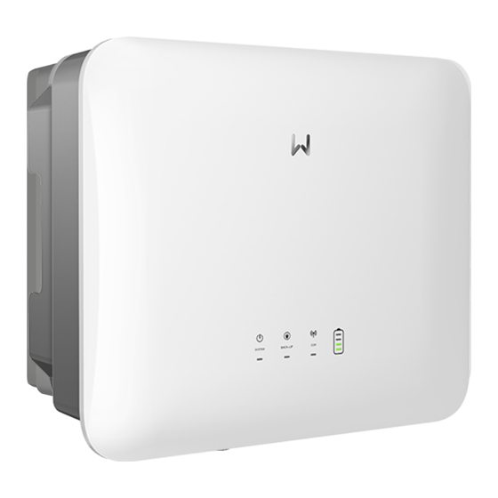
Page 20: Indicator Description
03 Product Introduction User Manual V1.0-2022-07-20 3.5.3 Indicator Description Indicator Status Description The inverter is power on and in the standby mode. The inverter is starting up and in the self-check mode. The inverter is in normal operation under grid-tied or off-grid modes. -
Page 21: Nameplate
User Manual V1.0-2022-07-20 03 Product Introduction 3.5.4 Nameplate The nameplate is for reference only. GW trademark, product type, and product model Technical parameters Safety symbols and certification marks Contact information and serial number... -
Page 22: Check And Storage
04 Check and Storage User Manual V1.0-2022-07-20 4 Check and Storage 4.1 Check Before Receiving Check the following items before receiving the product. 1. Check the outer packing box for damage, such as holes, cracks, deformation, and others signs of equipment damage. Do not unpack the package and contact the supplier as soon as possible if any damage is found. -
Page 23: Storage
User Manual V1.0-2022-07-20 04 Check and Storage 4.3 Storage If the equipment is not to be installed or used immediately, please ensure that the storage environment meets the following requirements: 1. Do not unpack the outer package or throw the desiccant away. 2. -
Page 24: Installation
05 Installation User Manual V1.0-2022-07-20 5 Installation 5.1 Installation Requirements Installation Environment Requirements 1. Do not install the equipment in a place near flammable, explosive, or corrosive materials. 2. Do not install the equipment in a place that is easy to touch, especially within children’s reach. High temperature exists when the equipment is working. - Page 25 User Manual V1.0-2022-07-20 05 Installation Mounting Support Requirements • The mounting support shall be nonflammable and fireproof. • Install the equipment on a surface that is solid enough to bear the inverter weight. • Do not install the product on the support with poor sound insulation to avoid the noise generated by the working product, which may annoy the residents nearby.
- Page 26 05 Installation User Manual V1.0-2022-07-20 Installation Tool Requirements The following tools are recommended when installing the equipment. Use other auxiliary tools on site if necessary. Safety RJ45 Safety Goggles Dust mask gloves crimping tool shoes Wire Diagonal Hammer Vacuum Heat gun stripper pliers cleaner...
-
Page 27: Inverter Installation
User Manual V1.0-2022-07-20 05 Installation 5.2 Inverter Installation 5.2.1 Moving the Inverter CAUTION • Operations such as transportation, turnover, installation and so on must meet the requirements of the laws and regulations of the country or region where it is located. •... - Page 28 05 Installation User Manual V1.0-2022-07-20 Diameter: 10mm Depth: 80mm Only Australia.
-
Page 29: Electrical Connection
BACK-UP ports. Otherwise, it may cause electric shock. • Only ES series inverters support PV string connection. N and PE cables are connected together in the Main Panel for wiring. - Page 30 06 Electrical Connection User Manual V1.0-2022-07-20 N and PE cables in the Main Panel shall be wired separately. NOTICE Ensure that the grounding of BACK-UP is correctly and tightened. Otherwise, the BACK-UP function may be abnormal in case of grid failure. Other areas except Australia, New Zealand, South Africa, etc., are applicable to the following wirings: Main Panel...
-
Page 31: Safety Precaution
User Manual V1.0-2022-07-20 06 Electrical Connection 6.2 Safety Precaution DANGER • All operations, cables and parts specification during the electrical connection shall be in compliance with local laws and regulations. • Disconnect the DC switch and the AC output switch of the inverter to power off the inverter before any electrical connections. -
Page 32: Connecting The Ac Cable
06 Electrical Connection User Manual V1.0-2022-07-20 Copper, 4mm ≤ S ≤ 6mm 6.4 Connecting the AC cable WARNING • Do not connect loads between the inverter and the AC switch directly connected to the inverter. • The residual current monitoring unit (RCMU) is integrated into the inverter. When the inverter detects the leakage current is bigger than the allowable value, it can disconnect from the grid quickly. - Page 33 User Manual V1.0-2022-07-20 06 Electrical Connection WARNING • Connect the battery cables to the corresponding terminals such as “L”, “N” and “PE” ports correctly. Otherwise it will cause damage to the inverter. • Ensure that the whole cable cores are inserted into the terminal holes. No part of the cable core can be exposed.
- Page 34 06 Electrical Connection User Manual V1.0-2022-07-20 Type II Supported by GW3600M-ES-20, GW5000M-ES-20, GW6000M-ES-20, GW6000-SBP-20 inverters Copper, 2.5mm ≤ S ≤ 4mm...
-
Page 35: Connecting The Dc Input Cable(Pv)
PV string to the ground meets the minimum insulation resistance requirements before connecting the PV string to the inverter (R=maximum input voltage/ 30mA). If the insulation resistance value is less than above requirement, it will trigger the insulation resistance alarming in the inverter. Only for ES series inverters. Click 7~8mm 7~8mm... - Page 36 06 Electrical Connection User Manual V1.0-2022-07-20 Click Click ≤ 600V Devalan 7~8mm 7~8mm Click Click ≤ 600V...
-
Page 37: Connecting The Battery Cable
User Manual V1.0-2022-07-20 06 Electrical Connection 6.6 Connecting the battery cable DANGER • The battery used with the inverter shall be approved by the inverter manufacturer. The approved battery list can be obtained through the official website. • A short circuit in the battery may cause personal injury. The instantaneous high current caused by a short circuit can release a large amount of energy and may cause a fire. - Page 38 06 Electrical Connection User Manual V1.0-2022-07-20 10mm 9.5-12.5mm 10mm 9.5-12.5mm 20mm ≤ S ≤ 35mm...
-
Page 39: Communication
User Manual V1.0-2022-07-20 06 Electrical Connection 6.7 Communication NOTICE Make sure that the communication device is connected to the right COM port. Route the communication cable far away from any interference source or power cable to prevent the signal from being influenced. 6.7.1 Connecting the COM cable (Load Control, Remote Shutdown, DI Signal, Generator Control, DRED, RCR and EMS) Port Definition... - Page 40 06 Electrical Connection User Manual V1.0-2022-07-20 Remote Load Control Shutdown 1: DO1+ 4: Remote 2: N/A Shutdown 3: DO1- 5: GND Generator 6: DI+ 8: DO2+ 7: DI- 9: DO2- Color EMS/PAR Orange and White RS485A (EMS) Orange RS485B (EMS) Green and White DRED or RCR 10: COM/DRM0 or REF_1...
-
Page 41: Connecting Bms Or Meter Com Cable
User Manual V1.0-2022-07-20 06 Electrical Connection 6.7.2 Connecting BMS or Meter COM Cable NOTICE • The communication cables between BMS and the battery, and between Meter and the inverter are delivered with the inverter, with default length of 3m and 10m separately. Please install the Meter and CT according to the actual situations. - Page 42 06 Electrical Connection User Manual V1.0-2022-07-20 NOTICE Power Limit functionality can be realized when the inverter is installed with the Meter. The specific networking schemes are: Power Limit networking scheme (Single phase scenario) When the load connected is single-phase and no PV inverter is used under the self consumption mode, the Power Limit can be realized by connecting ES and SBP series inverters with GM1000.
- Page 43 User Manual V1.0-2022-07-20 06 Electrical Connection Power Limit networking scheme (Split phase scenario) When the load connected is split phase, the Power Limit can be realized by connecting ES and SBP series inverters with GM3000. Connect the cables by following below requirements. Otherwise, it may cause Power Limit function failed.
-
Page 44: Installing The Com Module
• It supports setting the inverter; connecting to the server for monitoring the inverter and power plant operations etc. via WiFi Kit, Wi-Fi/LAN Kit and 4G module. • Refer to the delivered communication module user manual to get more introduction to the module. For more detailed information, visit www.goodwe.com. -
Page 45: Equipment Commissioning
Step 2: Turn on the AC breaker on the BACK-UP side of the inverter. Step 3: Turn on the battery breaker between the inverter and the battery. Step 4: (optional, only for ES series inverters) Turn on the DC switch of the inverter. -
Page 46: System Commissioning
08 System Commissioning User Manual V1.0-2022-07-20 8 System Commissioning 8.1 Indicators and Buttons Indicator Status Description The inverter is power on and in the standby mode. The inverter is starting up and in the self-check mode. The inverter is in normal operation under grid-tied or off-grid modes. -
Page 47: Setting Inverter Parameters Via Pv Master App
2. Set grid parameters, communication parameters, etc. 3. Maintain the equipment. 4. Upgrade the software version of the inverter. For more details, refer to PV Master User Manual. Scan the QR code or visit GoodWe official site to get the user manual. https://en.goodwe.com/Ftp/EN/Downloads/User%20Manual/GW_PV%20Master_User%20 Manual-EN.pdf... -
Page 48: Maintenance
Step 2: Turn off the AC breaker on the BACK-UP side of the inverter. Step 3: Turn off the battery breaker between the inverter and the battery. Step 4: (optional, only for ES series inverters) Turn off the DC switch of the inverter. 9.2 Removing the Inverter WARNING •... -
Page 49: Troubleshooting
User Manual V1.0-2022-07-20 09 Maintenance 9.4 Troubleshooting Perform troubleshooting according to the following methods. Contact the after-sales service if these methods do not work. Collect the information below before contacting the after-sales service, so that the problems can be solved quickly. •... - Page 50 09 Maintenance User Manual V1.0-2022-07-20 Fault Cause Solutions 1. If the problem occurs occasionally, the utility grid may be abnormal temporarily. The inverter will recover automatically after detecting that the utility grid is normal. 2. If the problem occurs frequently, check whether the grid voltage is within the The grid voltage is permissible range.
- Page 51 User Manual V1.0-2022-07-20 09 Maintenance Fault Cause Solutions 1. If the problem occurs occasionally, the utility grid may be abnormal temporarily. The inverter will recover automatically after detecting that the utility grid is normal. 2. If the problem occurs frequently, check The moving whether the grid voltage is within the average of grid...
- Page 52 09 Maintenance User Manual V1.0-2022-07-20 Fault Cause Solutions 1. If the problem occurs occasionally, the utility grid may be abnormal temporarily. The inverter will recover automatically after detecting that the utility grid is normal. 2. If the problem occurs frequently, check Utility grid whether the grid frequency is within the exception.
- Page 53 User Manual V1.0-2022-07-20 09 Maintenance Fault Cause Solutions The utility grid is disconnected. The utility grid is disconnected 1. Check whether the utility grid is according Anti-islanding disconnected. to the safety 2. Contact the dealer or the after-sales service. regulations, but the grid voltage is maintained due to the loads.
- Page 54 09 Maintenance User Manual V1.0-2022-07-20 Fault Cause Solutions Large DC of AC 1. If the problem is caused by an external fault The DC current L1 like a utility grid exception or frequency component of the exception, the inverter will recover output current automatically after solving the problem.
- Page 55 User Manual V1.0-2022-07-20 09 Maintenance Fault Cause Solutions 1. Frame format error 2. Parity checking error 3. Can bus offline Disconnect the AC output switch and DC input 4. Hardware CRC Internal Comm switch, then connect them 5 minutes later. error Loss Contact the dealer or the after-sales service if...
- Page 56 09 Maintenance User Manual V1.0-2022-07-20 Fault Cause Solutions 1. The DC terminal is not firmly Read the Quick Installation Guide and check DC Arc Fault connected. whether the cables are connected properly. 2. The DC cable is broken. Disconnect the AC output switch and DC input AFCI Self-check AFCI detection is switch, then connect them 5 minutes later.
- Page 57 User Manual V1.0-2022-07-20 09 Maintenance Fault Cause Solutions 1. The PV Disconnect the AC output switch and DC input PV Continuous configuration is switch, then connect them 5 minutes later. Software not proper. Contact the dealer or the after-sales service if Overcurrent 2.
-
Page 58: Routine Maintenance
09 Maintenance User Manual V1.0-2022-07-20 9.5 Routine Maintenance WARNING • Make sure that the inverter is powered off. • Wear proper PPE before any operations. Maintaining Item Maintaining Method Maintaining Period Check the heat sink, air intake, and air outlet System Clean Once 6-12 months for foreign matter or dust. -
Page 59: Technical Parameters
User Manual V1.0-2022-07-20 10 Technical Parameters 10 Technical Parameters 10.1 ES Series Technical Parameters Technical Data GW3000- GW3600- GW3600M- GW5000- GW5000M- GW6000- GW6000M- ES-20 ES-20 ES-20 ES-20 ES-20 ES-20 ES-20 Battery Input Data Battery Type* Li-Ion Li-Ion Li-Ion Li-Ion Li-Ion... - Page 60 10 Technical Parameters User Manual V1.0-2022-07-20 Technical Data GW3000- GW3600- GW3600M- GW5000- GW5000M- GW6000- GW6000M- ES-20 ES-20 ES-20 ES-20 ES-20 ES-20 ES-20 Start-up Voltage (V) Nominal Input Voltage (V) Max. Input Current per MPPT (A) Max. Short Circuit Current per MPPT (A) Max.
- Page 61 User Manual V1.0-2022-07-20 10 Technical Parameters Technical Data GW3000- GW3600- GW3600M- GW5000- GW5000M- GW6000- GW6000M- ES-20 ES-20 ES-20 ES-20 ES-20 ES-20 ES-20 Nominal 220 / 220 / 220 / 230 220 / 230 220 / 230 / 220 / 230 / 220 / 230 / Output 230 /...
- Page 62 10 Technical Parameters User Manual V1.0-2022-07-20 Technical Data GW3000- GW3600- GW3600M- GW5000- GW5000M- GW6000- GW6000M- ES-20 ES-20 ES-20 ES-20 ES-20 ES-20 ES-20 Maximum Output Overcurrent Protection (A) Type of Voltage (a.c. or a.c. a.c. a.c. a.c. a.c. a.c. a.c. d.c.) AC Output Data (Back-up) Back-up Nominal...
- Page 63 User Manual V1.0-2022-07-20 10 Technical Parameters Technical Data GW3000- GW3600- GW3600M- GW5000- GW5000M- GW6000- GW6000M- ES-20 ES-20 ES-20 ES-20 ES-20 ES-20 ES-20 Nominal Output 50/60 50/60 50/60 50/60 50/60 50/60 50/60 Frequency (Hz) Output THDv (@Linear <3% <3% <3% <3% <3% <3% <3%...
- Page 64 10 Technical Parameters User Manual V1.0-2022-07-20 Technical Data GW3000- GW3600- GW3600M- GW5000- GW5000M- GW6000- GW6000M- ES-20 ES-20 ES-20 ES-20 ES-20 ES-20 ES-20 Overcurrent Integrated Protection AC Short Circuit Integrated Protection Overvoltage Integrated Protection DC Switch Integrated DC Surge Type II Protection AC Surge Type III...
- Page 65 User Manual V1.0-2022-07-20 10 Technical Parameters Technical Data GW3000- GW3600- GW3600M- GW5000- GW5000M- GW6000- GW6000M- ES-20 ES-20 ES-20 ES-20 ES-20 ES-20 ES-20 Weight (kg) 19.6 20.8 20.0 21.5 20.0 21.5 20.0 Dimension 505.9×434.9×154.8 (W×H×D mm) Noise <30 Emission (dB) Topology Non-isolated Self- consumption...
- Page 66 10 Technical Parameters User Manual V1.0-2022-07-20 Technical Data GW3000- GW3600- GW3600M- GW5000- GW5000M- GW6000- GW6000M- ES-20 ES-20 ES-20 ES-20 ES-20 ES-20 ES-20 Type of Electrical single phase Supply System Country of China Manufacture Certifications & Standards* Grid AS4777.2-2020; NRS 097-2-1; CEI 0-21 Standards Safety IEC62109-1&2...
-
Page 67: Sbp Series Technical Parameters
User Manual V1.0-2022-07-20 10 Technical Parameters 10.2 SBP Series Technical Parameters Technical Data GW3600-SBP-20 GW5000-SBP-20 GW6000-SBP-20 Battery Input Data Battery Type Li-Ion Li-Ion Li-Ion Nominal Battery Voltage (V) Battery Voltage Range (V) 40~60 40~60 40~60 Max. Continuous Charging Current (A)* Max. - Page 68 10 Technical Parameters User Manual V1.0-2022-07-20 Technical Data GW3600-SBP-20 GW5000-SBP-20 GW6000-SBP-20 Maximum Output Overcurrent Protection (A) Type of Voltage (a.c. or d.c.) a.c. a.c. a.c. AC Output Data (Back-up) Back-up Nominal Apparent 3,680 5,000 6,000 Power (VA) Max. Output Apparent Power 3,680 5,000 6,000...
- Page 69 User Manual V1.0-2022-07-20 10 Technical Parameters Technical Data GW3600-SBP-20 GW5000-SBP-20 GW6000-SBP-20 Communication with BMS Communication with Meter RS485 Communication with Portal WiFi / WiFi + LAN / 4G Weight (kg) 19.2 19.5 19.5 Dimension (W×H×D mm) 505.9×434.9×154.8 Noise Emission (dB) <30 <30 <30...
- Page 70 Official Website GoodWe Technologies Co.,Ltd. No. 90 Zijin Rd., New District, Suzhou, 215011, China www.goodwe.com service@goodwe.com Contact Information...
Need help?
Do you have a question about the ES Series and is the answer not in the manual?
Questions and answers