Goodwe SMT Series User Manual
Grid-tied pv inverter
Hide thumbs
Also See for SMT Series:
- User manual (64 pages) ,
- Quick installation manual (22 pages) ,
- User manual (55 pages)
Table of Contents
Advertisement
Advertisement
Table of Contents

Subscribe to Our Youtube Channel
Related Manuals for Goodwe SMT Series


Summary of Contents for Goodwe SMT Series
- Page 1 User Manual Grid-Tied PV Inverter SMT Series V3.0-2021-11-22...
-
Page 2: Table Of Contents
Contents 目录 Symbols �������������������������������������������������������������������� 01 Safety and warning ��������������������������������������������������� 02 Product introduction ������������������������������������������������ 04 3�1 Intended usage ��������������������������������������������������������������������04 3�2 Inverter Overview ����������������������������������������������������������������05 3�3 Packing List ��������������������������������������������������������������������������06 Installation ��������������������������������������������������������������� 07 4�1 Mounting Instructions ����������������������������������������������������������07 4�2 Select The Installation Location ��������������������������������������������07 4�3 Inverter Installation��������������������������������������������������������������08 4�4 Electrical Connection �����������������������������������������������������������09 4�5 Communication Connection �������������������������������������������������13 Power On ������������������������������������������������������������������... -
Page 3: Symbols
Symbols Improper handling of this device will pose a risk of injury. Recyclable materials Danger of high voltage & electric shock This side up - The package must always have the arrows point up Don't touch, hot surface! No more than six (6) identical packages be stacked on each other Special disposal instructions Fragile Keep Dry... -
Page 4: Safety And Warning
Safety and warning This manual contains important instructions for SMT series inverter that shall be followed during installation of the inverter. The SMT series for Three MPPT, Three-Phase solar inverter without transformer. SMT Series have been designed and tested strictly according to the international safety regulation. - Page 5 • It is recommended to add a fuse when there is more than two PV string inputs into one MPPT. The IP65 premise is that the machine is completely sealed. Please install it within one day after unpacking, otherwise please block the unconnected port and do not open it to ensure that the machine is not exposed to water and dust.
-
Page 6: Product Introduction
Product introduction 3�1 Intended usage The SMT series which is a Three MPPT, three phase transformer-less grid-connected inverter is a crucial unit between the PV string and the utility grid in the PV power system. Inverter is dedicated to converting directing current generated by the PV module into alternating current, and feeding it into the utility grid, this conforms to parameters of the local utility grid. -
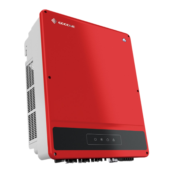
Page 7: 3�2 Inverter Overview
3�2 Inverter Overview Check the product once unpacking it to make sure the model is the right one you purchased. As the figure below shows, ports or terminals in different SMT inverters may differ. Parts DC Switch PV Input Terminal Communication Module USB/DRED/Remote RS485... -
Page 8: 3�3 Packing List
3�3 Packing List The unit is thoroughly tested and strictly inspected before delivery. Damage may still occur during shipping. 1. Check the packing for any visible damage upon receiving. 2. Check the inner contents for damage after unpacking. 3. Check the package list below. Negative PV Mounting Positive PV... -
Page 9: Installation
Installation 4�1 Mounting Instructions • In order to achieve optimal performance, the ambient temperature should be lower than 45℃. • For easy maintenance, we suggest to install the inverter at eye level. • Inverters should not be installed near flammable and explosive items. Strong electro- magnetic charges should be kept away from installation site. -
Page 10: 4�3 Inverter Installation
To ensure heat dissipation and convenient disassembly, the minimum clearance around the inverter should not be less than the following values. ≥300mm ≥600mm ≥600mm ≥300mm ≥500mm 4�3 Inverter Installation Avoid the water pipes and cables buried in the wall when drilling holes. Installing inverters without handles... -
Page 11: 4�4 Electrical Connection
Installing inverters with handles 1.6~2N·m 4�4 Electrical Connection 4�4�1 Connection To Grid (AC Side Connection) 1. Measure the voltage and frequency of grid-connected access point, and make sure it is accordance with the grid-connected standard of inverter. 2. It is recommended to add a breaker or fuse to AC side, the specification should be more than 1.25 times of rated of AC output current. - Page 12 N PE L1 L2L3 3.8~4.2N·m 0.6~0.8N·m...
- Page 13 4�4�2 AC Circuit Breaker And Residual Current Device An independent three or four pole circuit breaker for each inverter must be installed at the output side to ensure that the inverter can be securely disconnected from the grid. Inverter model Recommended nominal current of AC breaker GW12KLV-MT >40A...
- Page 14 7~8mm Φ: 4~5mm 7~8mm 2.5mm2≤S≤4mm2 Click Click ≤1100V...
-
Page 15: 4�5 Communication Connection
4. DRM function is achieved by Ezlogger Pro or DRED COM port, please connect the Ezlogger Pro through RS485 port. You can refer to EzLogger Pro SERIES USER MANUAL. Visit https://en.goodwe.com/Public/ Uploads/sersups/GW_EzLogger%20Pro_User%20Manual-EN.pdf to get the user manual Inverter... - Page 17 Connecting DRED or RS485 6pin Communication Cable (optional) Contat the after-sales service to get the DRED terminal if you need to use DRED function. DRED RS485 6.5mm 25mm NO� DRED NO� RS485 DRED1 RS485-A1 DRED2 RS485-B1 DRED3 RS485-A1 DRED4 RS485-B1 REF1 RS485-A2 REF2...
- Page 18 Connecting Remote Shutdown 2pin Communication Cable (optional) Remote Shutdown 6.5mm 25mm + SC-A - SC-B 0.6~0.8N·m Connecting USB Cable (optional)
- Page 19 Connecting RS485 5pin Communication Cable (optional) RS485 6.5mm 25mm NO� Function RS485-A1 RS485-B1 RS485-A1 RS485-B1 0.6~0.8N·m...
- Page 20 Connection Configurations in the attachment, and you can also refer to the description of "Demo Videos of Monitoring Installation" on the http://www.goodwe.com/DownLoad.aspx website. After the configurations are completed, please register on the website http://www.goodwe.com . Note: The name and password of WiFi cannot use symbols, only Arabic numerals or uppercase /...
-
Page 21: Power On
Power On 5�1 Check Before Power ON No� Check Item The inverter is firmly installed at a clean place where is well-ventilated and easy to operate. The PE cable, DC input cable, AC output cable, and communication cable are connected correctly and securely. Cable ties are routed properly and evenly, and no burrs. - Page 22 Indicator Status Description Steady green Power on Off Power off Power The grid is working normally. The Steady green inverter is connected to the grid. The inverter is not connected to the Off grid. Operating Single green slow Self-check before connecting to the blinking grid.
-
Page 23: Configure Setting
Configure Setting 6�1 Commissioning via LCD 6�1�1 User Interface Introduction WiFi 36.00 20.5kWH 93.3kWH E-DAY E-TOTAL CARBON 01/01/2020 00:00:00 Normal ①: Communication information icon:GPRS and WiFi show the signal strength, RS485 shows the communication address. ②: Communication icon:The way of communication,There are GPRS, WiFi and RS485 ③: LVRT/HVRT icon:The icon indicates that the system LVRT/HVRT function is on ④: Grid Type icon:The icon indicates that the system select Delta Grid/Star Grid ⑤: Power limit icon:The Power limit icon indicates that the Power limit function is on... - Page 24 6�1�2 User Interface Introduction The display menu through the Up, Down, Enter, Esc key to operate the menu, which Enter key is divided into long press (greater than 3s)and short press, so a total of five key operation. Press the Enter Esc key to toggle the 123 menu, use the up and down keys to select the item and change the parameters, and long press the Enter (short press is also ok for some item) to set the parameters.
- Page 25 Level 1 menu Level 2 menu Level 3 menu Contry Code Contry Code Set Home Hour Select Data Select Data Running Info Configuration Month Select Data History Info Year Select Data Device Info Language Set Language Basic Date&Time Set Date&Time Advanced Communication Set Address...
- Page 26 6�1�4 System Configuration Basic Settings Basic Settings is mainly used to set the commonly used parameters, including language settings, time settings, communication settings and safety settings for projects. And these parameters could be set by App. WiFi WiFi Basic Advanced Basic Advanced 01/01/2020 00:00:00...
- Page 27 WiFi WiFi Country Code WiFi Country Code Language Holland Holland Data&Time Northlreland Northlreland Communication ChinaHigher ChinaHigher Country Code France 50Hz France 50Hz Grid Connection France 60Hz France 60Hz 01/01/2020 00:00:00 Fault 01/01/2020 00:00:00 Fault 01/01/2020 00:00:00 Fault WiFi WiFi Grid Connection Language Disconnected Data&Time...
- Page 28 Advanced Settings User must enter password to operate advanced settings because permission is required. Note: Initial password: "1111". Advanced Settings include nine Settings: 1. Power limit; 2. CT ratio; 3. Power factor; 4. Shadow scanning; 5. Low Voltage Ride Through; 6. High Voltage Ride Through; 7. Type of power grid; 8. Reset the password;...
- Page 29 WiFi Adv�Settings WiFi Shadow Power Limit CT Ration PF Value Shadow LVRT 01/01/2020 00:00:00 01/01/2020 00:00:00 Normal Normal WiFi Adv�Settings WiFi LVRT Power Limit CT Ration PF Value Shadow LVRT 01/01/2020 00:00:00 Normal 01/01/2020 00:00:00 Normal WiFi Adv�Settings WiFi HVRT HVRT Grid Type Password...
- Page 30 History Information The history information mainly includes the information of the generating capacity of the equipment, the power generation information mainly includes the amount of electricity generation, daily power generation, monthly power generation and annual power generation information. History Info WiFi Hour Month...
- Page 31 2. Set grid parameters and communication parameters of the inverter. 3. Maintain the equipment. For more details, refer to the SolarGo APP User Manual. Scan the QR code or visit https://www. goodwe.com/ to get the user manual. SolarGo App SolarGo App...
-
Page 32: 6�3 Monitoring Via Sems Portal App
6�3 Monitoring via SEMS Portal App play SEMS Portal App Store SEMS Portal APP... -
Page 33: Maintenance
Maintenance Regular maintenance ensures a long operating life and optimal efficiency of the entire PV plant. Before maintenance please disconnect the AC breaker first and then disconnect DC breaker. Wait 5 minutes until the residual voltage has been released. 7�1 Clearing The Fan Series inverter is equipped with three fans on its left side. -
Page 34: 7�3 Checking The Electrical Connection
Shutdown order: 1. Turn off the breaker on AC side. 2. Turn off the DC switch. 3. Turn off the breaker on DC side. Caution: if there is no switch, step 2 is not required. 7�3 Checking The Electrical Connection 1. -
Page 35: Troubleshooting
Troubleshooting In most situations, the inverter requires very little maintenance. However, if the inverter is not working properly, please try the following solutions: Type of fault Alarm Troubleshooting 1.Disconnect DC switch, take off DC connector, check the impedance between PV (+) & PV (-) to earth. 2. - Page 36 Type of fault Alarm Troubleshooting Relay-check Failure DCI High 1. Disconnect the DC connector. EEPROM R/W Failure Inverter 2. Reconnect the DC connector. Failure SPI Failure 3. If the problem still exists, please call the local service office. DC Bus High GFCI Failure 1.
-
Page 37: Technical Parameters & Block Diagram
Technical Parameters & Block Diagram 9�1 Technical Parameters Technical Data GW12KLV-MT GW15KLV-MT GW20KLV-MT Input ( DC) Max. DC Input Power (Wp) 15600 19500 26000 Max. DC Input Voltage (V) MPPT Operating Voltage Range (V) 200~650 MPPT Operating Voltage Range for Full 360~600 Load (V) Start-up Voltage (V) - Page 38 Technical Data GW12KLV-MT GW15KLV-MT GW20KLV-MT DC Insulation Resistance Detection Integrated Anti-islanding Protection Integrated DC Reverse Polarity Protection Integrated Insulation Resistance Detection Integrated DC Surge Arrester Type III (Type II optional) AC Surge Arrester Type III (Type II optional) Output Over current Protection Integrated Output Short Protection Integrated...
- Page 39 Technical Data GW25K-MT GW29.9K-MT GW30K-MT GW36K-MT Input ( DC) Max. DC Input Power (Wp) 32500 39000 39000 42900 Max. DC Input Voltage (V) 1100 MPPT Operating Voltage 200~950 Range (V) MPPT Operating Voltage 510~860 Range for Full Load (V) Start-up Voltage (V) Nominal DC Input Voltage (V) Max.
- Page 40 Technical Data GW25K-MT GW29�9K-MT GW30K-MT GW36K-MT Residual Current Monitoring Integrated Unit DC Insulation Resistance Integrated Detection Anti-islanding Protection Integrated DC Reverse Polarity Integrated Protection DC Surge Arrester Type III (Type II Optional) AC Surge Arrester Type III (Type II Optional) Output Overcurrent Integrated Protection...
- Page 41 Technical Data GW25K-MT GW29�9K-MT GW30K-MT GW36K-MT Protective class Class I Topology Transformerless [1]: 33kW for Italy,36kW for other country. [2]For Belgium Max. Output Power (W): GW25K-MT is 25000; GW30K-MT is 30000; GW36K-MT is 36000. [3]:For Belgium Max. Output Apparent Power (VA): GW25K-MT is 25000; GW30K-MT is 3000; GW36K-MT is 36000.
- Page 42 Note: Overvoltage Category Definition Category I: applies to equipment connected to a circuit where measures have been taken to reduce transient overvoltage to a low level. Category II: applies to equipment not permanently connected to the installation. For example, appliances, portable tools and other plug-connected equipment; Category III: applies to fixed downstream equipment, including the main distribution board.
-
Page 43: 9�2 Block Diagram
9�2 Block Diagram SMT series main circuit is shown in the below figure: OUT FILTER SWITCH BOOST AC RELAY PV1+ PV1- PV2+ Filter Filter PV2- Filter PV3+ PV3-... - Page 44 GoodWe Website Jiangsu Goodwe Power Supply Technology Co., Ltd No. 90 Zijin Rd., New District, Suzhou, 215011, China www.goodwe.com service@goodwe.com Local Contacts...
Need help?
Do you have a question about the SMT Series and is the answer not in the manual?
Questions and answers