Table of Contents
Advertisement
Advertisement
Table of Contents

Related Manuals for Xtool D9 Pro


Summary of Contents for Xtool D9 Pro
- Page 1 USER MANUAL D9 Pro Smart Diagnosis System Shenzhen Xtooltech Intelligent Co., LTD...
-
Page 3: Trademarks
Shenzhen Xtooltech Intelligent CO., LTD. In countries that the trademarks, service marks, domain names, logos, and the name of the company are not registered, Xtool claims that it still reserves the ownership of the unregistered trademarks, service marks, domain names, logos, and the company name. -
Page 4: Declaration
ECLARATION This manual is designed for the usage of the D9 PRO Smart Diagnosis System and provides operating instructions and product descriptions for users of the D9 PRO Smart Diagnosis System. No part of this manual can be reproduced, stored in a retrieval system, or... -
Page 5: Cautions
Keep the device away from heat or fumes when you are using it. ⚫ If the vehicle battery contains acid, please keep your hands and skin ⚫ or fire sources away from the battery during testing. The exhaust gas of the vehicle contains harmful chemicals, please ⚫... - Page 6 If necessary, calibrate the screen before testing to ensure the accuracy ⚫ of LCD performance. Keep the main unit away from strong magnetic fields. ⚫ Please keep your device always connected to the Internet. When the ⚫ device is off the Internet for 30 days, The diagnosis APP may be locked and you need to synchronize data with the Internet to activate it.
-
Page 7: Table Of Contents
Content TRADEMARKS ....................I COPYRIGHT ....................... I DECLARATION ....................II OPERATION INSTRUCTIONS ..............II CAUTIONS! ...................... III AFTERSALES-SERVICES ................IV GENERAL INTRODUCTION ..............1 Tablet ..........................2 Front View of Tablet ............................2 Back View of Tablet ............................3 Host Ports................................4 VCI box .......................... - Page 8 Activation Guide ................错误!未定义书签。 UPDATE ....................25 DIAGNOSIS .................... 27 Vehicle Connection ..................... 27 Vehicle Selection ......................29 Basic Diagnosis Functions ..................34 ECU Coding & Programming ..................45 SPECIAL FUNCTIONS ................ 49 Oil Reset ................... 错误!未定义书签。 EPB ..................... 错误!未定义书签。 SAS .....................
- Page 9 REPORT ....................50 Report ....................错误!未定义书签。 Replay ....................错误!未定义书签。 File Manager ..................错误!未定义书签。 SETTINGS ....................87 Language ........................88 Units ..........................89 Bluetooth ........................90 My Workshop Info ....................... 90 VCI Information......................91 About ..........................92 REMOTE ASSISTANCE ..............93 SHENZHEN XTOOLTECH INTELLIGENT CO., LTD ......
-
Page 10: General Introduction
ENERAL NTRODUCTION The D9 PRO smart diagnosis system is an advanced scanning tool based on the Android operating system. It supports multi-language switching and is suitable for different countries and regions. The advantage of this scanner is not only its comprehensive functions, including complete system diagnosis, full OBDⅡfunctions, various reset... -
Page 11: Tablet
TABLET OVERVIEW The main unit of the D9 PRO Smart Diagnosis System is the tablet. It allows you to operate all diagnosis functions, and it can also work as a normal Android tablet. FRONT VIEW OF TABLET Figure 1-1 Sample of Tablet Front View... -
Page 12: Back View Of Tablet
BACK VIEW OF TABLET ① ③ ② ④ Figure 1-2 Sample of Tablet Back View ① Camera: Used for taking pictures. ② Tablet Holder: Used to support the tablet, hold the tablet on the steering wheel or adjust the tablet height as needed. ③... -
Page 13: Host Ports
HOST PORTS ③ ⑤ ④ ② ① Figure 1-3 Sample of Tablet Host Ports ① DOIP port: Supports ECU programming for vehicles with DOIP protocol ② USB 3.0 port: Used for data transfer for tablet & PC communication, and data transfer with VCI box when working. ③... -
Page 14: Vci Box
VCI BOX To communicate with the vehicle via OBD, D9 PRO also comes up with a VCI box. The tablet needs a Bluetooth connection with the VCI box to get access to all software. Although some functions (like EEPROM Adapter) will not need you to communicate to the vehicle, please power up the VCI box using a 12V power adapter to get access to the software. -
Page 15: Top/Bottom View Of Vci Box
TOP/BOTTOM VIEW ① ② Bottom Figure 1-5 Sample of VCI Box, screen 2 ① DB15 Port: Used to connect the VCI box to the OBDII port on the vehicle. ② USB-B Port: Used to connect the VCI box to the tablet using USB-B to USB3.0 cable... -
Page 16: Technical Specifications
TECHNICAL SPECIFICATIONS Table 1-1 Specification Item Description Android 5.1 Processor Quad-core processor 1.8GHz Display 9.7-inch capacitive, 1024×768 resolution ⚫ USB Connectivity ⚫ Wi-Fi ⚫ Bluetooth 8-megapixel autofocus rear camera with Camera flash Sensor Gravity sensor Audio Input/ Audio Microphone/ Loudspeaker Output ⚫... -
Page 17: Packing Kit
PACKING KIT Table 1-2 Packing List Category Name HONDA-3 TOYOTA-17 BMW-20 KIA-20 MAZDA-17R NISSAN-14 GM/DAEWOO-12 SUZUKI-3 FIAT-3 HYUNDAI/KIA-10 Test connector AUDI-4 MITSUBISHI-12+16 UNIVERSAL-3 CITROEN-2 BENZ-38 BENZ-14 SELFTEST OBD II-16 DB15 Main Cable Battery Cable Cigar Lighter Cable Tablet PC VCI Box Host group USB3.0 To Type_B Main Cable Charger for Tablet... - Page 18 Power Cable EU USB3.0 Data Cable (Connect to Color Carton Packing List Certificate of Quality Accessories Tool Case Desiccant User Manual...
-
Page 19: Getting Started
ETTING TARTED ACTIVATION After first-time users press and hold the power button to turn on the system, the system will automatically enter the guide process and request to select the language for the operating system. Figure 2-1 Sample of Selection Languages After setting the system language, you will enter the activation page, as shown in the figure below. - Page 20 Figure 2-2 Sample of Activation (Screen 1) Click Start Activate to enter the activation page, as shown below: Figure 2-3 Sample of Activation (Screen 2)
-
Page 21: Main Interface
A pop-up window showing Activation Success indicates that you have completed the first boot setup, click OK to enter the diagnostic system and start using the device. Figure 2-4 Sample of Activation (Screen 3) MAIN INTERFACE OPERATION SYSTEM The picture below (Fig 2-1) is the home screen of the operating system of the device. - Page 22 Figure 2-5 Sample of OS Main page The app icons are as follows: Table 2-1 Items Descriptions Browser Gallery Application Menu ES File Explorer...
- Page 23 Local/Home/Cleaner to clean up files. If you need to check the files inside the D9 PRO Smart Diagnosis System app (not recommended), please use the file explorer inside the D9 PRO Smart Diagnosis System app.
- Page 24 D9 PRO Smart Diagnosis System: This app provides full system diagnostic functions and also offers a range of specialist maintenance services. It will be referred to as the “D9 PRO Smart Diagnosis System App” later in this manual.
-
Page 25: Main Menu
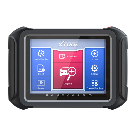
MAIN MENU Every time start the tablet, you will automatically enter the D9 PRO Smart Diagnosis System app with the following main screen. Tap on the diagnosis application button on the menu, the main menu will be shown as below: Figure 2-7 Sample of APP Main Page This main menu contains Function Buttons and Navigation Buttons. -
Page 26: Function Buttons
Select the language and unit shown in the app, and check the Bluetooth status, device info, and workshop info View extended functions like checking reports and checking Xtool official website Check the diagnosis report that recorded on your device, prints it as PDF files, or share it with other devices... -
Page 27: Navigation Buttons
NAVIGATION BUTTONS Instructions for operating the navigation bar buttons at the bottom of the screen, as described in the table below: Table 2-2 Items Descriptions Press for screenshot Decrease volume Back to the previous interface Shows recently used applications Back to the main interface of the Android system Increase volume Showing the Bluetooth states Click this button to return to the diagnostic vehicle... -
Page 28: Notification Bar
NOTIFICATION BAR Slide down to open the notification bar. You can adjust the brightness of the screen when you need it, and you can also connect Wi-Fi and so on. Figure 2-8 Sample of NOTIFICATION BAR... - Page 29 FACTORY RESET After using the device for the first time or resetting the factory settings to the device, the system will automatically enter the Activation Guide program. This page allows you to set the language of the device operating system Figure 2-9 Sample of How to Select Languages After selecting the system language, click Next to enter the Wi-Fi connection page, as shown below:...
- Page 30 Figure 2-10 Sample of Selecting Wi-Fi Select a network to connect to on the Wi-Fi connection page. After successful network connection, the automatic system will jump to Factory mode to download the software:...
- Page 31 Figure 2-11 Sample of Factory Mode Once the software has been downloaded, the tablet will automatically reboot and request the system language selection again. Figure 2-12 Sample of Selecting Languages After setting the system language, you will enter the activation page, as shown in the figure below.
- Page 32 Figure 2-13 Sample of Activation, Screen 1 Click Start Activate to enter the activation page, as shown below: Figure 2-14 Sample of Activation, Screen 2...
- Page 33 OK to enter the diagnostic system and start using the device. Figure 2-15 Sample of Activation, Screen 3 If you meet problems like “Registration failed”, please check your network or contact Xtool aftersales services: supporting@xtooltech.co...
-
Page 34: Update
Figure 3-1 Sample of How to Update Vehicle Software D9 PRO Smart Diagnosis System has a three-year free subscription when activated. When you click “update” and it shows “your device is now out of subscription”, please... - Page 35 DELETE SOFTWARE Long-press the unwanted software until it has been selected, then click the Delete button shown on the upper part of the screen. And you can select and delete multiple software at once. Figure 3-2 Sample of How to Delete Vehicle Software ** When the device prompts that the memory is insufficient, you can delete the models that are not frequently used to release the memory.
-
Page 36: Diagnosis
IAGNOSIS The diagnosis application can read ECU information, read and clear DTCs and check living data and freeze frames. The diagnosis application can access the electronic control unit (ECU) of various vehicle control systems, including the engine, transmission, anti- lock braking system (ABS), airbag system (SRS), and perform kinds of actuation tests. - Page 37 Some older vehicles are not using the OBD2-16 port, please make sure you’re using the correct connector. Some extra OBD Ⅰ connectors are attached to D9 PRO Smart Diagnosis System, please contact your dealer if you need other connectors.
-
Page 38: Vehicle Selection
VEHICLE SELECTION Click the “Diagnosis” icon on the main screen and get into the diagnosis menu. All brands will be shown on the screen. Please select the region of your vehicle, click the correct brand, and start the diagnosis process. Fig 4-2 Sample of Vin Identification Click the VIN button in the upper left corner, you can choose to enter the vehicle diagnosis through the first 3 ways of AUTO SCAN/SCAN... - Page 39 It supports automatic reading of vehicle VIN code. You also can tap on the button “AUTO SCAN” on the diagnosis system entrance to use this function. Please make sure that the car and the device are well connected before using this function. Fig 4-3 Sample of AUTOSCAN ⚫...
- Page 40 Fig 4-4 Sample of Manually Inputting Vin ⚫ SELECT VEHICLE BY AREA In addition to the above 3 methods, you can also choose a car brand according to the region. You can select the vehicle model that needs to be diagnosed according to the area, as shown below:...
- Page 41 Figure 4-5 Sample of Vehicle Selection by Ares OBD-Ⅱsupports reading the related fault codes of PCM; DEMO, a demonstration program; Click this button to experience and learn the operation process of the diagnostic function For some of the vehicle brands (like Volkswagen), when you click on the software, there are several ways to select the model or system you want to run a diagnosis, including Automatic Detection, Manual Selection, and System Selection.
- Page 42 Fig 4-6 Sample of Vehicle Detection Method Automatic Detection will automatically identify the vehicle's VIN code, and then read the information of your target diagnostic object. If you choose "Manual selection", then you can continue to select the vehicle brand, year, and model of the vehicle in the sub-menu to diagnosis the vehicle.
-
Page 43: Basic Diagnosis Functions
BASIC DIAGNOSIS FUNCTIONS D9 Pro Smart Diagnosis System supports 5 basic diagnosis functions: Read ECU Information ⚫ Read/Clear Trouble Code ⚫ Read Live Data ⚫ Actuation Test (Bi-Directional Control) ⚫ Freeze Frame ⚫ Figure 4-7 Sample of Basic Function ◼ Read ECU Information This function is to read ECU version information, which is the equivalent of "System Identification"... - Page 44 control systems, which means to read ECU-related software and hardware versions, models, and production date of diesel engine, part number, etc. Figure 4-8 Sample of ECU Information ◼ Read Trouble Code Read trouble codes that are stored in ECU. For the fault code, the diagnostic instrument will give specific detailed definitions and explanations to help you locate and eliminate the car fault.
- Page 45 Figure 4-9 Sample of Read DTC In the process of diagnosis, if the device shows “System is OK” or “No Trouble Code”, it means there is no related trouble code stored in ECU or some troubles are not under the control of ECU, most of these troubles are mechanical system troubles or executive circuit troubles, it is also possible that signal of the sensor may bias within limits, which can be judged in Live Data.
- Page 46 car before it can be cleared with a diagnostic tool. Non-permanent fault codes can be cleared directly with the diagnostic tool. Figure 4-10 Sample of Clear DTC The trouble codes can’t be erased without eliminating all the troubles, which will cause the diagnostic tool to always read the trouble code because the code will always be saved in ECU.
- Page 47 problems such as performance characteristics offset, sensitivity reduction, can be judged in live data. In the process of diagnosis, if the device shows “System is OK” or “No Trouble Code”, it means there is no related trouble code stored in ECU or some troubles are not under the control of ECU, most of these troubles are mechanical system troubles or executive circuit troubles, it is also possible that signal of the sensor may bias within limits, which can be...
- Page 48 ⚫ Click the magnifying glass on the top right, you can search for related PIDs based on keywords Figure 4-12 Sample of the PIDs List related by Key Words ⚫ Custom Support to show the selected PIDs.
- Page 49 Figure 4-13 Sample of Custom the PIDs Click Display All, back to the page which display all PIDs ⚫ Data recording Supports recording the current data value in the form of text, you can Reports->Data Replay. view the recorded files in ⚫...
- Page 50 Support to select multiple PIDs and click 【Combine】 to make different graphs into one chart. Figure 4-14 Sample of the PIDs Combination Note: When customizing the graphs, the number of PIDs selected at a time should not exceed 5 ◼ Actuation Test Actuation test, also known as bidirectional control, is a generic term used to describe sending and receiving information between one device and another.
- Page 51 The vehicle engineers responsible for designing computer control systems programmed them so a scan tool could request information or command a module to perform specific tests and functions. Some manufacturers refer to bidirectional controls as functional tests, actuator tests, inspection tests, system tests, or the like. Reinitialization and reprogramming also can be included in the list of bidirectional controls.
- Page 52 control module (PCM), and the PCM responds by sending the information back to the scan tool for display. Most enhanced scan tools also can actuate relays, injectors, and coils, perform system tests, etc. Users could check the individual part to see what is working properly by actuation test. Figure 4-16 Sample of the Actuation Test ◼...
- Page 53 The living data items supported by vehicles of different brands are not the same, so the freeze frames displayed when diagnosing vehicles of different brands may also be different. Some vehicles may not have the option of freeze frame which means that the model does not support this function.
-
Page 54: Ecu Coding & Programming
ECU CODING & PROGRAMMING Since the introduction of OBD II and leading up to modern Hybrids and EVs, computers, and software in cars have been expanding at an exponential rate. In-car software is becoming one of the leading needs for service, and updating software may be the only way to fix some of these issues: •... - Page 55 NOTE: Codable control modules/components are system-specific, which means that not all control modules are codable. ⚫ ECU Programming ECU Online programming means a user could download the latest version of the software from the online server database through Internet access (this procedure is done automatically when the tablet is connected to the Internet, so there is no need to check for software updates yourself), and reprograms the newest version into the ECU of vehicles.
- Page 56 so that the tablet computer can access the vehicle manufacturer's server for update services. ⚫ Selecting the programming or coding function will open a menu of operating options, which differs depending on the vehicle’s make and model. Selecting a menu option either displays a programming interface or opens another menu containing other options.
- Page 57 the previous operation does not succeed. Please use this feature with caution and it is not recommended for non-professionals.
-
Page 58: Special Functions
Due to the limitation of screenshots, the special functions shown in this picture are not complete. All special functions supported by the D9 PRO Smart Diagnosis System are subject to the actual special functions displayed on the device. -
Page 59: Oil Reset
◼ Below we will introduce the 15 most commonly used service & maintenance functions 5.1 OIL RESET Reset the Engine Oil Life System, which calculates the optimum oil life change interval based on the vehicle’s driving conditions and climate. The oil life reminder must be reset each time the oil is changed so that the system can calculate when the next oil change is required. - Page 60 Follow the instructions displayed and press OK after completing the instructions shown. Figure 5-2 Sample of oil reset function (screen 1) Enter Maintenance mileage reset menu. Input reasonable value of mileage and press OK.
-
Page 61: Epb
Figure 5-3 Sample of oil reset function (screen 2) Message of ‘Reset success’ displayed when Oil Reset function has successfully performed. 5.2 EPB Electronic Parking Brake (EPB) System reset is a popular special function. You can use this function to reset the electronic parking brake system and brake pads, which also supports the brake pad replacement (retraction, release of the brake pump), G-sensor, and body angle calibration. - Page 62 These applications include deactivating and activating brake control systems, assisting in controlling brake fluid, opening and closing brake pads, setting brakes after replacing brake discs or brake pads, etc. 1. If the brake pad wears the brake pad sense line, the brake pad sense line will send a signal to the onboard tablet asking for replacing the brake pad.
- Page 63 Figure 5-4 Sample of EPB function (screen 1) Enter the Enter maintenance mode menu and release the handbrake brake. And press OK after completing the instructions shown.
-
Page 64: Sas
Figure 5-5 Sample of EPB function (screen 2) Wait until the message of ‘Successful operation’ popes up. And press OK to exit the menu. Enter the Exit maintenance mode menu and wait until the message of ‘‘Successful operation’ popes up. 5.3 SAS Steering Angle Sensors (SAS) System Calibration permanently stores the current steering wheel position as the straight-ahead... - Page 65 After replacing the steering angle position sensor, replacing steering mechanical parts (such as steering gearbox, steering column, end tie rod, steering knuckle), performing four-wheel alignment, or recovering the car body, you must reset the steering angle. The operation guidelines of the SAS function are shown as below: Enter the SAS menu and choose relevant models according to the vehicle being tested.
- Page 66 Wait until the following instruction is displayed and press Yes after completing the instructions shown. Figure 5-7 Sample of SAS function (screen 2)
- Page 67 Follow the instructions displayed and press OK after completing the instructions shown. Figure 5-8 Sample of SAS function (screen 3) Wait until the following instruction is displayed and press OK after completing the instructions shown.
-
Page 68: Dpf
Figure 5-9 Sample of SAS function (screen 4) Message of ‘Function execution is completed’ displayed when SAS function has successfully performed. 5.4 DPF Diesel Particle Filter (DPF) function manages regeneration, DPF component replacement teach-in, and DPF teach-in after replacing the engine control module (ECM). The ECM monitors driving style and selects a suitable time to employ regeneration. - Page 69 DPF regeneration is used to clear PM (Particulate Matter) from the DPF filter through continuous combustion oxidation mode (such as high-temperature heating combustion, fuel additive or catalyst reduce PM ignition combustion) to stabilize the filter performance. DPF regeneration may be performed in the following cases: The exhaust back pressure sensor is replaced.
- Page 70 Figure 5-10 Sample of DPF function (screen 1) Read the fuel tank level and make sure that it fulfills the requirement displayed. Read the carbon deposit load. Choose the drive to warm up and follow the instructions listed below. And press OK after completing the instructions shown.
- Page 71 Figure 5-11 Sample of DPF function (screen 2) Read the note carefully and follow the instructions shown on the screen. And press OK after completing the instructions shown. Figure 5-12 Sample of DPF function (screen 3) Follow the instructions displayed and press OK after...
- Page 72 completing the instructions shown. Please pay attention to the Note. Figure 5-13 Sample of DPF function (screen 4) Press the OK button to start the regeneration. Figure 5-14 Sample of DPF function (screen 5)
- Page 73 10. Wait for the value of carbon deposit to decrease until a message of ‘Emergency regeneration has been completed’ popes up, this process may take up to 40 minutes. Figure 5-15 Sample of DPF function (screen 5)
- Page 74 11. Wait for 2 minutes to let the particulate filter cool down. Figure 5-16 Sample of DPF function (screen 6) 12. Press drop out to exit the DPF function.
-
Page 75: Bms Reset
5.5 BMS RESET The Battery Management System (BMS) allows the scan tool to evaluate the battery charge state, monitor the close-circuit current, register the battery replacement, and activate the rest state of the vehicle. This function enables you to perform a resetting operation on the monitoring unit of the vehicle battery, in which the original low battery fault information will be cleared and battery matching will be done. - Page 76 instrument cluster. The operation guidelines of the BMS Reset function are shown as below: Enter the BMS Reset menu and choose relevant models according to the vehicle being tested. Turn on the ignition switch. Press OK to continue the BMS function. Enter battery capacity (within the given range) and press OK after the input.
- Page 77 Figure 5-18 Sample of BMS function (screen 2) Enter the 10-digit battery serial number and press OK after the input.
-
Page 78: Throttle
Figure 5-19 Sample of BMS function (screen 3) 5.6 THROTTLE Throttle Position Sensor (TPS) Match, this function enables you to make initial settings to throttle actuators and returns the “learned” values stored on ECU to the default state. Doing so can accurately control the actions of regulating throttle (or idle engine) to adjust the amount of air intake. - Page 79 Figure 5-20 Sample of throttle function (screen 1) Wait until all the parameters are read and displayed. Figure 5-21 Sample of throttle function (screen 2)
- Page 80 Press the F2 button and wait until a message of ‘Match successfully’ pops up. 5.7 INJECTOR CODING This function can write the identification code of the fuel injector into the ECU so that the ECU can recognize and work normally. Write actual injector code or rewrite code in the ECU to the injector code of the corresponding cylinder for controlling accurately and correcting cylinder injection quantity.
- Page 81 The operation guidelines of the Injector Coding function are shown as below: Enter the Injector coding menu and choose relevant chassis models according to the vehicle being tested. Enter the Fuel injection nozzle injection volume adjustment menu. Read the note displayed carefully and press OK after the reading. Figure 5-22 Sample of injector coding function (screen 1) Read and confirm the value stored in the cylinders.
- Page 82 Figure 5-23 Sample of injector coding function (screen 2) Enter the Change the value of cylinder menu of the replaced injector(s), enter the new 5-digit value, and then press OK.
- Page 83 Figure 5-24 Sample of injector coding function (screen 3) Wait until the message ‘Write successfully’ pops up. Turn off the ignition switch. Wait until the message asked you to turn on the ignition switch. Re-enter the Fuel injection nozzle injection volume adjustment menu to check whether the new value(s) are shown.
- Page 84 5.8 GEARBOX MATCH After changing the gearbox or changing the gearbox ECU, you need to use the gearbox matching function to re-match the engine and the gearbox. Before resetting the gearbox, please check the gearbox control unit to ensure that there is no fault code. If there is a fault code, the gearbox memory function cannot be reset.
- Page 85 Figure 5-26 Sample of gearbox matching function (screen 1) Wait until the message ‘Successful operation’ popes up. 5.9 GEAR LEARNING The crankshaft position sensor learns crankshaft tooth machining tolerance and saves to the tablet to more accurately diagnose engine misfires. If gear learning is not performed for a car equipped with a Delphi engine, the MIL turns on after the engine is started.
- Page 86 the MIL turns off. This function can complete the self-learning of the gearbox and improve the quality of shifting. After the engine ECU, crankshaft position sensor, or crankshaft flywheel is replaced, or the DTC 'gear not learned' is present, gear learning must be performed.
- Page 87 Figure 5-27 Sample of gear learning function (screen 1) Read the instructions displayed and press Yes to start the learning process. Figure 5-28 Sample of gear learning function (screen 2)
- Page 88 Press the accelerator pedal down and hold it until a message of ‘The learning is successful, please release the accelerator pedal.’ pops up. Release the accelerator pedal and press OK to exit the gear learning function.
-
Page 89: Report
EPORT Diagnostic Report is used for viewing and printing the saved files, such as Live Data, Trouble codes or pictures generated in the process of diagnosis, users also can view a record of which cars have been previously tested. It includes 3 parts: Report ⚫... - Page 90 REPORT This feature provides a history of diagnostic reports, where you can view and delete the vehicle's diagnostic reports according to your needs. Figure 6-2 Sample of Report List When you open the report, located in the header of the table is the studio information you filled in advance in the system setup, then the information of the vehicle, including the diagnosis date and time, VIN, vehicle brand, diagnosis path, etc., as shown as below:...
- Page 91 Figure 6-3 Sample of Report ◼ Print PDF Report As you can see, you also could click " Print PDF Report " at the bottom right corner to output the pdf report. If you need to close the report, you could tap on the button “Exit”.
- Page 92 Step 2: Back to the Android main menu, go to Settings -> Printing-> Turn printer on. Step 3: Report-> Choose report-> Print PDF Report-> Print Figure 6-4 Sample of How to Print Report, Screen 1 Step 4: Click the top-left corner of the screen and choose the printer you added before.
- Page 93 Figure 6-5 Sample of Report, Screen 2 REPLAY This function allows you to replay the living data recorded during the diagnosis process. Figure 6-6 Sample of Data Playback, Screen 1 Before replaying the living data, please make sure you click on the "Save to Reference"...
-
Page 94: File Manager
Figure 6-7 Sample of Data Playback, Screen 2 FILE MANAGER This function allows you to check and delete files on the device. Please use this function under the guidance of professionals. Ordinary users are not recommended to use it by themselves! - Page 95 Figure 6-8 Sample of File Manager...
-
Page 96: Settings
ETTINGS Figure 7-1 Sample of Settings Click the Settings button to adjust the default settings and view the information of the D9 PRO SMART DIAGNOSIS SYSTEM. There are several options available in the system settings: Language ⚫ Units ⚫ Bluetooth ⚫... -
Page 97: Language
LANGUAGE The languages supported by this device are listed in Settings. In areas outside the English area, the default language is English and the local official language. Users can switch between English and local official languages on the device by themselves. If you need to switch other languages, please contact the dealer to unbind the current language configuration and rebind it to the language configuration you need to switch. -
Page 98: Units
➢ Step4: Back to Updates to pull all packages again UNITS You can switch the unit used by the system. D9 PRO provides you with metric, imperial, and U.S. units. You can directly click on the unit when you need it, after the switch is successful, a blue checkmark will be shown behind the unit’s name. -
Page 99: Bluetooth
BLUETOOTH You can check the Bluetooth connection status here. If you meet any communication issues, please check the Bluetooth status first. Figure 7-4 Sample of Bluetooth Selection MY WORKSHOP INFO Click on My Workshop Information, you can input your workshop information here. -
Page 100: Vci Information
generate a diagnostic report, including your company name, address, website, telephone, and mailbox. Figure 7-5 Sample of Workshop Information VCI INFORMATION You can view the VCI information here, including the VCI firmware name, the latest firmware version, the currently used firmware version, and the VCI firmware type. -
Page 101: About
Figure 7-6 Sample of VCI Firmware Information Before updating the VCI Firmware, please ensure the tablet’s connection to the Internet is stable. ABOUT Tap on ABOUT, you can check the serial number and APP version here. Figure 7-7 Sample of About Information... -
Page 102: Remote Assistance
PC through the TeamViewer software, thereby obtaining temporary remote support from the Xtool technical support centre. Figure 8-1 Sample of Activating Team Viewer, Screen 1 Tablets and mobile devices running TeamViewer are identified by a globally unique ID. - Page 103 4. Provide your ID to the partner or Xtool technician, and then wait for him/her to send you a remote-control request. 5. A pop-up window will be shown asking you to confirm to allow the remote-control program to control your device.
- Page 104 9 FAQ Q1: FAILED TO GENERATE DIAGNOSIS REPORT 1. Currently only perform diagnostic functions, that is, read ECU information, read code and clear code, live data, freeze frame, which can trigger a diagnostic report. Other functions, such as immobilization and maintenance services will not be displayed in the report.
- Page 105 Fig 9-1 Sample1: How to clear APP cache Fig 9-2 Sample1: How to clear APP cache...
- Page 106 Fig 9-3 Sample1: How to clear APP cache Q2: HOW TO PRINT DIAGNOSIS REPORT The XTOOL device is compatible with third-party print drivers. You can download the printer driver you need in the browser that comes with the tablet to install it, and then set your printer in the OS settings. After the...
- Page 107 Q3: FAILED TO EXTRACT FILES Since the XTOOL tablet is equipped with an Android system, you have to confirm the system type of receiver. For Android: supports transferring files via Bluetooth, USB cable, etc.; For IOS: only supports transferring files through a wired connection (Bluetooth connection is not available).
- Page 108 Q7: HOW TO SWITCH LANGUAGE 1. Contact your dealer and leave a message about the language you need and the S/N of your device, The technician will modify the language configuration for you in the backend system. 2. Settings->Language->Choose language 3.
- Page 109 Generally caused by network instability, please switch to a more stable network and try to activate again. ⚫ For ‘Registration Failed’ Generally, it is caused by the connection timeout or the sending timeout, please check whether you have blocked the outgoing network traffic to non-US regions like China.
- Page 110 the device can be connected to the Internet normally, and your device still cannot use the diagnostic function, please contact our technical team (supporting@xtooltech.com) Q12: FAILED TO ENTER VEHICLE MENU If you encounter the following two prompts, please delete the package and download it again to diagnose ⚫...
- Page 111 LIMITED ONE YEAR WARRANTY Shenzhen Xtooltech Intelligent Co., LTD.(the Company) warrants to the original retail purchaser of this XTOOL device that should this product or any part thereof during normal usage and under normal conditions be proven defective in material or workmanship that results in product failure...
- Page 112 The Company shall not be liable for any incidental or consequential damages arising from the use, misuse, or mounting of the device. This warranty does not apply to: Products subjected to abnormal use or conditions, accident, mishandling, neglect, unauthorized alteration, misuse, improper installation/repair or, improper storage;...
-
Page 113: Shenzhen Xtooltech Intelligent Co., Ltd
., L HENZHEN TOOLTECH NTELLIGENT Company address: 17&18/F, Building A2, Creativity City, Liuxian Avenue, Nanshan District, Shenzhen, China Factory address: 2/F, Building 12, Tangtou Third Industrial Zone, Shiyan Street, Baoan District, Shenzhen, China Service-Hotline: 0086-755-21670995/86267858 Email: marketing@xtooltech.com supporting@xtooltech.com Fax: 0755-83461644 Website: www.Xtooltech.com...
Need help?
Do you have a question about the D9 Pro and is the answer not in the manual?
Questions and answers