Table of Contents
Advertisement
Advertisement
Table of Contents

Related Manuals for Xtool D9 Smart


Summary of Contents for Xtool D9 Smart
- Page 1 USER MANUAL D9 Smart Diagnosis System Shenzhen Xtooltech Intelligent Co., LTD...
-
Page 2: Trademarks
CO., LTD. In countries that the trademarks, service marks, domain names, logos, and the name of the company are not registered, Xtool claims that it still reserves the ownership of the unregistered trademarks, service marks, domain names, logos, and the company name. All other marks for the other products and the company’s name mentioned in the... -
Page 3: Declaration
ECLARATION This manual is designed for the usage of the D9 Smart Diagnosis System and provides operating instructions and product descriptions for users of the D9 Smart Diagnosis System. No part of this manual can be reproduced, stored in a retrieval system,... -
Page 4: Cautions
The exhaust gas of the vehicle contains harmful chemicals, please ensure adequate ventilation. Do not touch the cooling system components or exhaust manifolds when the engine is running due to the high temperatures reached. Make sure the car is securely parked, Neutral is selected or the ... -
Page 5: Aftersales-Services
be locked and you need to synchronize data with the Internet to activate it. FTERSALES ERVICES E-Mail: supporting@xtooltech.com Tel: +86 755 21670995 or +86 755 86267858 (China) Official Website: www.xtooltech.com Please provide your device serial number, VIN code, vehicle model, software version, ... -
Page 6: Table Of Contents
Content TRADEMARKS....................I COPYRIGHT.....................I DECLARATION....................II OPERATION INSTRUCTIONS..............II CAUTIONS!.....................III AFTERSALES-SERVICES................IV 1 GENERAL INTRODUCTION..............1 Tablet......................2 Front View of Tablet.................. 2 Back View of Tablet...................3 Host Ports....................4 VCI box......................5 Front/Back View of VCI BOX..............5 Top/Bottom View of VCI BOX..............6 Technical Specifications................ - Page 7 Notification Bar..................15 Activation Guide..................16 3 UPDATE......................19 4 DIAGNOSIS....................21 Vehicle Selection..................23 Diagnose Functions................25 5 SPECIAL FUNCTIONS................32 Oil Reset....................33 EPB......................33 SAS......................34 DPF......................35 BMS Reset....................36 Throttle.......................36 TPMS Reset..................... 37 ABS Bleeding................... 37 Injector Coding..................38 Gearbox Match..................38 Suspension....................
- Page 8 Replay......................44 File Manager.....................44 7 SETTINGS....................45 Language....................46 Units......................47 Bluetooth....................48 My Workshop Info..................48 VCI Information..................49 About......................50 8 REMOTE ASSISTANCE................52...
-
Page 9: General Introduction
ENERAL NTRODUCTION The D9 smart diagnosis system is an advanced scanning tool based on the Android operating system. It supports multi-language switching and is suitable for different countries and regions. The advantage of this scanner is not only its comprehensive functions, including complete system diagnosis, full OBDⅡfunctions, various... -
Page 10: Tablet
TABLET The main unit of the D9 Smart Diagnosis System is the tablet. It allows you to operate all diagnosis functions, and it can also work as a normal Android tablet. FRONT VIEW OF TABLET Fig 1-1 Tablet Front View... -
Page 11: Back View Of Tablet
BACK VIEW OF TABLET ③ ② ④ Fig 1-2 Tablet Back View Camera: Used for taking pictures. Tablet Holder: Used to support the tablet, hold the tablet on the steering wheel or adjust the tablet height as needed. Nameplate: Show the basic information about the tablet such as product name and serial number, etc. -
Page 12: Host Ports
Fig 1-3 Tablet Host Ports DOIP port: Supports ECU programming for vehicles with DOIP protocol. (Doesn’t support in D9 Smart Diagnosis System) USB 3.0 port: Used for data transfer for tablet & PC communication, and data transfer with VCI box when working on immobilizer reset process. -
Page 13: Vci Box
VCI BOX To communicate with the vehicle via OBD, D9 also comes up with a VCI box. The tablet needs a Bluetooth connection with the VCI box to get access to all the immobilizer & diagnosis software. Although some functions (like EEPROM Adapter) will not need you to communicate to the vehicle, please power up the VCI box using a 12V power adapter to get access to the software. -
Page 14: Top/Bottom View Of Vci Box
TOP/BOTTOM VIEW OF VCI BOX ② Bottom Fig 1-5/1-6 VCI box top/bottom View DB15 Port: Used to connect the VCI box to the OBDII port on the vehicle. USB-B Port: Used to connect the VCI box to the tablet using USB- B to USB3.0 cable... -
Page 15: Technical Specifications
TECHNICAL SPECIFICATIONS Table 1-1 Specification Item Description Android 5.1 Processor Quad-core processor 1.8GHz Display 9.7-inch capacitive, 1024×768 resolution USB Connectivity Wi-Fi Bluetooth 8-megapixel autofocus rear camera with Camera flash Sensor Gravity sensor Audio Input/ Audio Microphone/ Loudspeaker Output ... -
Page 16: Packing Kit
PACKING KIT Category Name HONDA-3 TOYOTA-17 BMW-20 KIA-20 MAZDA-17R NISSAN-14 GM/DAEWOO-12 SUZUKI-3 FIAT-3 HYUNDAI/KIA-10 Test connector AUDI-4 MITSUBISHI-12+16 UNIVERSAL-3 CITROEN-2 BENZ-38 BENZ-14 SELFTEST OBD II-16 DB15 Main Cable Battery Cable Cigar Lighter Cable Tablet PC VCI Box USB3.0 To Type_B Main Cable Charger for Tablet Host group Power Cable US... -
Page 17: Getting Started
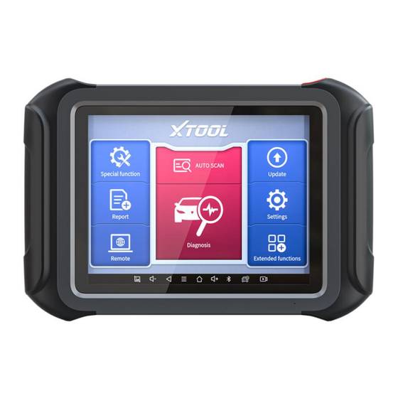
ETTING TARTED MAIN INTERFACE OPERATION SYSTEM The picture below (Fig 2-8) is the home screen of the operating system of the device. You can also return to this interface at any time clicking home button bottom navigation bar. Fig 2-1... - Page 18 D9 SMART DIAGNOSIS SYSTEM a) Browser: Click on the browser icon to enter the browser to view the official website of Xtool or search for other information. b) Gallery: Click the Gallery icon to enter the album and you can quickly view the pictures or screenshots stored on the device.
- Page 19 D9 Smart Diagnosis System: This app provides full system diagnostic functions and also offers a range of specialist maintenance services. It will be referred to as the “D9 Smart Diagnosis System App” later in this manual.
-
Page 20: Main Menu
MAIN MENU Every time you start the tablet, you will automatically enter the D9 Smart Diagnosis System app with the following main screen. Tap on the diagnosis application button on the menu, the main menu will be shown as below: Fig 2-3 This main menu contains Function Buttons and Navigation Buttons. -
Page 21: Function Buttons
Select the language and unit shown in the app, and check the Bluetooth status, device info, and workshop info View extended functions like checking reports and checking Xtool official website Check the diagnosis report that recorded on your device, prints it as PDF files, or share it with other devices... -
Page 22: Navigation Buttons
NAVIGATION BUTTONS Instructions for operating the navigation bar buttons at the bottom of the screen, as described in the table below: Table 2-3 Items Descriptions Back to the previous screen Back to the main screen of the Android system Shows recently used applications Press to screenshot Increase volume Click here to return to the diagnostic vehicle... -
Page 23: Notification Bar
NOTIFICATION BAR Slide down to open the notification bar. You can adjust the brightness of the screen when you need it, and you can also connect Wi-Fi and so on. Fig 2-4... -
Page 24: Activation Guide
ACTIVATION GUIDE After using the device for the first time or reset the factory settings to the device, the system will automatically enter the Activation Guide program. This page allows you to set the language of the device operating system Fig 2-5 After selecting the system language, click Next to enter the Wi-Fi connection page, as shown below:... - Page 25 Select a network to connect to on the Wi-Fi connection page. After successful network connection, the automatic system will jump to Factory mode to download the software: Fig 2-7 Once the software has been downloaded, the tablet will automatically reboot and request the system language selection again. Fig 2-8...
- Page 26 After setting the system language, you will enter the activation page, as shown in the figure below. You can also click the "Trial" button in the upper right corner to try it out before activation. Fig 2-9 Click Start Activate to enter the activation page, as shown below: Fig 2-10...
-
Page 27: Update
Fig 2-11 If you meet problems like “Registration failed”, please check your network or contact Xtool aftersales services: supporting@xtooltech.com PDATE After activating the device, please update the software in "Update" first. The device will pull all currently supported software packages from our servers, and you can download them as needed. - Page 28 Fig 3-1 D9 Smart Diagnosis System has a three-year free subscription when activated. When you click “update” and it shows “your device is now out of subscription”, please contact your dealer.
-
Page 29: Diagnosis
IAGNOSIS The diagnostic application can read ECU information, read and clear DTC and check living data and freeze frames. The diagnosis application can access the electronic control unit (ECU) of various vehicle control systems, including the engine, transmission, anti-lock braking system (ABS), airbag system (SRS), and perform kinds of actuation tests. - Page 30 2. Connect the vehicle, the VCI box and the tablet following the diagram below. Usually, the OBD port is located under the dashboard, inside driver’s footwell. 3. Wait for the VCI box to communicate with the tablet, then click into the menus to perform the functions. ...
-
Page 31: Vehicle Selection
VEHICLE SELECTION Click the “Diagnosis” icon on the main screen and get into the diagnosis menu. Like the immobilizer menu, the brands will be shown on the screen. Select the region of your vehicle, click the correct brand, and start the diagnosis process. Fig 4-2 For some of the vehicle brands (like Volkswagen), when you click on the software, there are several ways to select the model or system... - Page 32 Fig 4-3 Automatic Detection will automatically identify the vehicle's VIN code, and then read the information of your target diagnostic object. If you choose "Manual selection", then you can continue to select the vehicle brand, year, and model of the vehicle in the sub-menu to diagnosis the vehicle.
-
Page 33: Diagnose Functions
DIAGNOSE FUNCTIONS The Diagnosis System supports 5 basic diagnosis functions: Read ECU Information Read/Clear Trouble Code Read Live Data Actuation Test (Bi-Directional Control) Freeze Frame Fig 4-4 Read ECU Information This function is to read ECU version information, which is the equivalent of "System Identification"... - Page 34 software and hardware versions, models, and production date of diesel engine, part number, etc. Fig 4-5 Read Trouble Code Read trouble codes that are stored in ECU. For the fault code, the diagnostic instrument will give specific detailed definitions and explanations to help you locate and eliminate the car fault.
- Page 35 Fig 4-6 In the process of diagnosis, if the device shows “System is OK” or “No Trouble Code”, it means there is no related trouble code stored in ECU or some troubles are not under the control of ECU, most of these troubles are mechanical system troubles or executive circuit troubles, it is also possible that signal of the sensor may bias within limits, which can be judged in Live Data.
- Page 36 Fig 4-7 The trouble codes can’t be erased without eliminating all the troubles, which will cause the diagnostic tool to always read the trouble code because the code will always be saved in ECU. Read Live Data That is to read the parameters of the system, like for engine diagnosis, there are parameters like oil pressure, temperature, engine speed, fuel oil temperature, coolant temperature, intake air temperature, etc.
- Page 37 Fig 4-8 Actuation Test Actuation test, also known as bidirectional control, is a generic term used to describe sending and receiving information between one device and another. The vehicle engineers responsible for designing computer control systems programmed them so a scan tool could request information or command a module to perform specific tests and functions.
- Page 38 Fig 4-9 This function allows the device to send information to and receive information from, vehicle control modules. For example, in the case of OBD II generic information Mode 1 (which relates to data parameters), the scan tool user initiates a request for information from the powertrain control module (PCM), and the PCM responds by sending the information back to the scan tool for display.
- Page 39 Fig 4-10 Freeze Frame When the signal of the sensor is abnormal, the ECU will save the data at that moment of failure to form a freeze frame. It is usually used to analyze the reasons that may lead to car failures. The living data items supported by vehicles of different brands are not exactly the same, so the freeze frames displayed when diagnosing vehicle of different brands may also be different.
-
Page 40: Special Functions
Due to the limitation of screenshots, the special functions shown in this picture are not complete. All special functions supported by the D9 Smart Diagnosis System are subject to the actual special functions displayed on the device. Please make sure the vehicle you’re working on supports the original functions. -
Page 41: Oil Reset
▼Below we will introduce the 15 most commonly used service & maintenance functions OIL RESET Reset the Engine Oil Life System, which calculates the optimum oil life change interval based on the vehicle's driving conditions and climate. The oil life reminder must be reset each time the oil is changed so that the system can calculate when the next oil change is required. -
Page 42: Sas
applications include deactivating and activating brake control systems, assisting in controlling brake fluid, opening and closing brake pads, and setting brakes after replacing brake discs or brake pads, etc. 1. If the brake pad wears the brake pad sense line, the brake pad sense line sends a signal sense line to the onboard tablet to replace the brake pad. -
Page 43: Dpf
rod, steering knuckle), performing four-wheel alignment, or recovering the car body, you must reset the steering angle. The Diesel Particle Filter (DPF) function manages DPF regeneration, DPF component replacement teach-in, and DPF teach-in after replacing the engine control unit. The ECM monitors driving style and selects a suitable time to employ regeneration. -
Page 44: Bms Reset
The DPF regeneration MIL is on and maintenance is performed. The DPF regeneration control module is replaced. BMS RESET The Battery Management System (BMS) allows the scan tool to evaluate the battery charge state, monitor the close-circuit current, register the battery replacement, and activate the rest state of the vehicle. -
Page 45: Tpms Reset
values stored on ECU to the default state. Doing so can accurately control the actions of regulating throttle (or idle engine) to adjust the amount of air intake. TPMS RESET Tire Pressure Monitor System (TPMS) Reset allows you to quickly lookup the tire sensor IDs from the vehicle ECU, as well as to perform TPMS replacement and reset procedures after tire sensors are replaced. -
Page 46: Injector Coding
2. If the ABS tablet, ABS pump, brake master cylinder, brake cylinder, brake line, or brake fluid is replaced, the ABS bleeding function must be performed to bleed the ABS. 3. After the oil in the brake oil tank is seriously insufficient or the brake fluid is replaced, ABS Bleeding is also required When performing ABS Bleeding, it is necessary to unscrew the exhaust screw of the ABS ... -
Page 47: Suspension
*Cautions! Before resetting the gearbox, please check the gearbox control unit to ensure that there is no fault code. If there is a fault code, the gearbox memory function cannot be reset. Please road test after reset. SUSPENSION This function can adjust the height of the vehicle’s body. When replacing the body height sensor in the air suspension system, or control module or when the vehicle level is incorrect, you need to perform this function to adjust the body height sensor for level... -
Page 48: Seat Calibration
SEAT CALIBRATION This function is suitable for the matching of replacement and maintenance seats with memory functions. After the seat fails or is replaced or repaired, it is generally necessary to use this function to match the seat. Needed for cars with seats with memory function, general gasoline cars don’t need. ... -
Page 49: Report
Brushing to hide will not destroy the ECU system layer, but only open and close some functions. Most of them can be re-flashed multiple times. EPORT Diagnostic Report is used for viewing and printing the saved files, such as Live Data, Trouble Codes, or pictures generated in the process of diagnosis, users also can view a record of which cars have been previously tested. -
Page 50: Report
REPORT This feature provides a history of diagnostic reports, where you can view and delete the vehicle's diagnostic reports according to your needs. Fig 6-2 When you open the report, located in the header of the table is the studio information you filled in advance in the system setup, then the information of the vehicle, as shown as below:... - Page 51 IP address of the printer in the APP, or you can contact your dealer for help. D9 Smart Diagnosis System don’t provide the printer driver software, please install a third part App on the tablet if you need the print your diagnosis report.
-
Page 52: Replay
Fig 6-5 REPLAY This function allows you to replay the living data recorded during the diagnosis process. Before replaying the living data, please make sure you have record the live data during the diagnosis FILE MANAGER This function allows you to check and delete files on the device. Please use this function under the guidance of professionals. -
Page 53: Settings
ETTINGS Fig 7-1 Click the Settings button to adjust the default settings and view the information of the D9 SMART DIAGNOSIS SYSTEM. There are several options available in the system settings: Language Units Bluetooth My Workshop Info ... -
Page 54: Language
LANGUAGE The languages supported by this device are listed in Settings. In areas outside the English area, the default language is English and the local official language. Users can switch between English and local official languages on the device by themselves. If you need to switch other languages, please contact the dealer to unbind the current language configuration and rebind it to the language configuration you need to switch. -
Page 55: Units
Step1: Contact your dealer and leave a message about the language you need and the S/N of your device, The technician will modify the language configuration for you in the background. Step2: Settings->Language->Choose language Step3: OS Settings->Language & input->Choose Language ... -
Page 56: Bluetooth
BLUETOOTH You can check the Bluetooth connection status here. If you meet any communication issues, please check the Bluetooth status first. Fig 7-4 MY WORKSHOP INFO Click on My Workshop Information, you can input your workshop information here. As shown in the figure below, you just need to fill in the valid information in the corresponding column and click "SUBMIT". -
Page 57: Vci Information
Fig 7-5 VCI INFORMATION You can view the VCI information here, including the VCI firmware name, the latest firmware version, the currently used firmware version, and the VCI firmware type. If the current firmware version is lower than the latest firmware version, you can choose to update your firmware version and click "Update VCI Firmware"... -
Page 58: About
Fig 7-6 Before updating the VCI Firmware, please ensure the tablet’s connection to the Internet is stable. ABOUT Tap on ABOUT, you can check the serial number and APP version here. - Page 59 Fig 7-7...
-
Page 60: Remote Assistance
PC through the TeamViewer software, thereby obtaining temporary remote support from the Xtool technical support center. Fig 8-1 Tablets and mobile devices running TeamViewer are identified by a globally unique ID. - Page 61 4. Provide your ID to the partner or Xtool technician, and then wait for him/her to send you a remote-control request. 5. A pop-up window will be shown asking you to confirm to allow the remote-control program to control your device.
- Page 62 ., L HENZHEN TOOLTECH NTELLIGENT Company address: 17&18/F, Building A2, Creativity City, Liuxian Avenue, Nanshan District, Shenzhen, China Factory address: 2/F, Building 12, Tangtou Third Industrial Zone, Shiyan Street, Baoan District, Shenzhen, China Service-Hotline: 0086-755-21670995/86267858 Email: marketing@xtooltech.com supporting@xtooltech.com Fax: 0755-83461644 Website: www.Xtooltech.com...
- Page 63 FCC Statement This device complies with part 15 of the FCC rules. Operation is subject to the following two conditions: (1) this device may not cause harmful interference, and (2) this device must accept any interference received, including interference that may cause undesired operation. Changes or modifications not expressly approved by the party responsible for compliance could void the user's authority to operate the equipment.
Need help?
Do you have a question about the D9 Smart and is the answer not in the manual?
Questions and answers