Advertisement
Quick Links
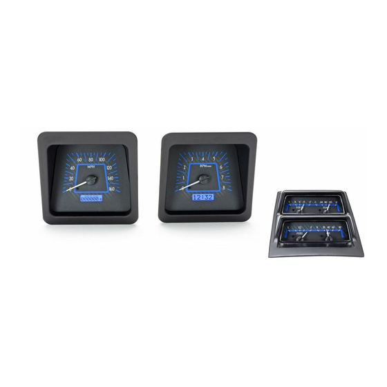
Your new VHX-69C-CAC kit will include:
VHX Displays
Universal Sensor
Pack
Switch Assembly
Installation
1. You may be able to access all of the fasteners with the dash carrier installed, so removing the
entire assembly may not be necessary. First, remove the clear lenses from the front. Next,
remove the original gauge internals; they are held into the housing with nuts from the backside.
VHX-69C-CAC
Dakota Digital VHX Instrument Installation
For '69 Chevy Camaro systems with Console Gauges
Installation Manuals
(2) 36" CAT5 Cables
(1) 24" CAT5 Cable
(2X) 10-32x1" Mounting Screws
(2X) Nylon washers
(2X) 10-32x1.5" Mounting Screws
(2X) Nylon Shoulder Washers
(2X) Thumb Nuts
(2X) Flat Spring Nuts
Foam Tape
Mounting Bracket
Control Box
Manual # 650423A
Advertisement

Related Manuals for Dakota Digital VHX-69C-CAC


Summary of Contents for Dakota Digital VHX-69C-CAC
- Page 1 VHX-69C-CAC Dakota Digital VHX Instrument Installation For ‘69 Chevy Camaro systems with Console Gauges Your new VHX-69C-CAC kit will include: VHX Displays Universal Sensor Pack Installation Manuals (2X) 10-32x1” Mounting Screws (2X) Nylon washers (2X) 10-32x1.5” Mounting Screws (2X) Nylon Shoulder Washers...
- Page 2 2. Once the original gauge internals have been removed, there are two reflectors (one on each side) inside the housing that need to be removed for clearance of the new VHX gauges (see photo). 3. Now, remove the light bulbs and indicator light panels. Since these functions are built into the VHX system, you can connect the indicator wires to the control box to retain the desired functions.
- Page 3 5. Begin with the speedometer installation, located in the left side opening in the factory dash. Cut three pieces of the supplied foam tape, 2” long. Install foam strips on the top and sides of each opening about ½” down from the face of the housing. This foam provides a cushion for the new VHX cans and forms a tight, rattle-free fit.
- Page 4 WRONG!!!! Cable will get pinched by the pull block Bezel flush with housing once fully seated in housing and cable properly routed 8. Using the two provided 10-32 x 1.5” screws and nylon shoulder washers, secure the speedometer assembly to the housing. Start the screws into the back of the factory housing and into the pull-block on the back of the gauge assembly.
- Page 5 10. Both cables should be routed through the stock indicator light opening; the system is ready for re- installation into the dash if it was removed. 24” CAT5 connecting both halves 36” CAT5 to control box 11. Next, the entire console will need to be removed. Looking at the picture of the console from the bottom, you can see there are four (4) mounting points.
- Page 6 13a. Place the bezel over the VHX system and be sure to align the tabs from the bezel into the slots cut into the VHX housing as shown. 13b. Attach the bezel to the VHX cluster using the original screws from disassembly and the two (2) flat spring nuts provided.
- Page 7 15. Carefully route both CAT5 cables to the control box mounting location and connect both to the control box. It doesn’t matter which cable goes where, all of the jacks are the same. 16. Display installation is complete; refer to the main manual for wiring instructions to complete the VHX installation.
- Page 8 Manual # 650423A...
Need help?
Do you have a question about the VHX-69C-CAC and is the answer not in the manual?
Questions and answers