Table of Contents
Advertisement
Quick Links
HPE ProLiant DL580 Gen10 Server User Guide
Abstract
This document is for the person who installs, administers, and troubleshoots HPE server systems. Hewlett Packard
Enterprise assumes that you are qualified in the servicing of computer equipment, and trained in recognizing hazards in
products with hazardous energy levels.
Part Number: 30-3C869113-405
Published: October 2021
Edition: 14
Advertisement
Table of Contents

Related Manuals for Hewlett Packard Enterprise HPE ProLiant DL580 Gen10


Summary of Contents for Hewlett Packard Enterprise HPE ProLiant DL580 Gen10
- Page 1 HPE ProLiant DL580 Gen10 Server User Guide Abstract This document is for the person who installs, administers, and troubleshoots HPE server systems. Hewlett Packard Enterprise assumes that you are qualified in the servicing of computer equipment, and trained in recognizing hazards in products with hazardous energy levels.
- Page 2 Copyright 2017–2021 Hewlett Packard Enterprise Development LP Notices The information contained herein is subject to change without notice. The only warranties for Hewlett Packard Enterprise products and services are set forth in the express warranty statements accompanying such products and services.
-
Page 3: Table Of Contents
Contents Component identification....................7 Front panel components......................................7 Universal media bay components..............................10 Drive bay numbering....................................10 Front panel LEDs and buttons....................................12 UID button functionality..................................14 Front panel LED power fault codes..............................14 Systems Insight Display LEDs................................15 Systems Insight Display combined LED descriptions......................16 Drives..............................................18 Hot-plug drive LED definitions................................ - Page 4 Removing a PCIe riser cage....................................47 Removing the air baffle......................................48 Installing the air baffle....................................... 49 Removing the fan cage......................................50 Installing the fan cage........................................51 Removing the fan cage holders....................................52 Installing fan cage holders.......................................52 Removing the processor mezzanine tray............................... 53 Removing the CPU Mezzanine UPI performance kit..........................54 Setup..........................56 HPE support services.........................................
- Page 5 Installing a processor..................................... 123 Installing a processor mezzanine tray................................126 Memory options..........................................127 DIMM population information................................127 DIMM-processor compatibility................................. 127 HPE SmartMemory speed information............................128 Installing a DIMM......................................128 Intel Optane persistent memory 100 series for HPE......................129 Installing the CPU Mezzanine UPI performance kit..........................133 HPE Smart Storage Battery....................................134 Installing a Smart Storage Battery..............................134 Installing an intrusion detection switch................................137...
- Page 6 HPE 800 W Flex Slot -48 VDC Hot-plug Low Halogen Power Supply..............192 HPE 1600 W Flex Slot Platinum Hot-plug Low Halogen Power Supply..............193 Websites......................... 194 Support and other resources..................195 Accessing Hewlett Packard Enterprise Support............................. 195 Accessing updates........................................195 Remote support..........................................196 Warranty information......................................196 Regulatory information......................................
-
Page 7: Component Identification
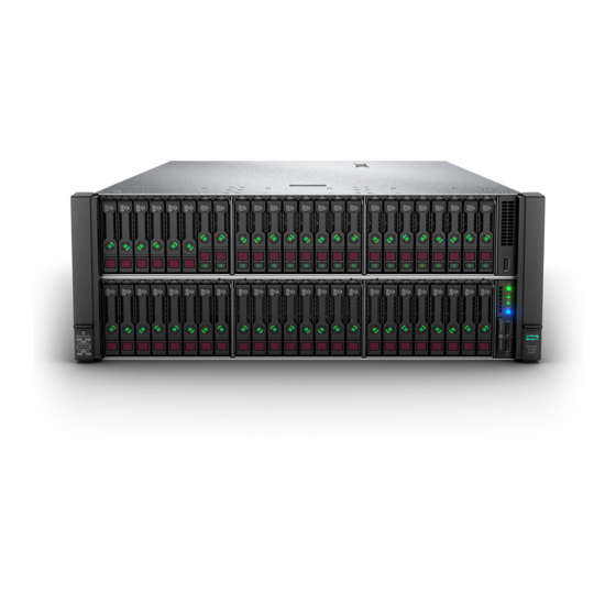
Component identification Front panel components Server with power module Item Description Box 1 — Supported options: Eight-bay SFF HDD/SSD drive cage • • Six-bay SFF HDD/Two-bay NVMe SSD (Premium) drive cage Eight-bay SFF NVMe SSD drive cage (with only four NVMe drives •... - Page 8 Item Description Serial number and iLO information pull tab iLO Service Port (169.254.1.2) Front USB 3.0 port Box 6 — Supported option: Eight-bay SFF HDD/SSD drive cage Box 5 — Supported option: Eight-bay SFF HDD/SSD drive cage Box 4 — Supported options: Universal media bay components •...
- Page 9 Item Description Box 1 — Supported options: • Eight-bay SFF HDD/SSD drive cage • Six-bay SFF HDD/Two-bay NVMe SSD (Premium) drive cage • Eight-bay SFF NVMe SSD drive cage (with only four NVMe drives installed) Box 2 — Supported options: •...
-
Page 10: Universal Media Bay Components
Universal media bay components Item Description USB 2.0 port Video display port Optical disk drive (optional) Drives (optional) Requires the two-bay SFF (Premium) drive cage Drive bay numbering Eight-bay SFF HDD/SSD drive cage Component identification... - Page 11 Eight-bay SFF NVMe drive cage Six-bay SFF HDD/Two-bay NVMe SSD (Premium) drive cage Component identification...
-
Page 12: Front Panel Leds And Buttons
Two-bay SFF (Premium) drive cage Front panel LEDs and buttons Power switch module Component identification... - Page 13 Systems Insight Display module (optional) Item Description Status Power On/Standby button and Solid green = System on system power LED Flashing green (1 Hz/cycle per sec) = Performing power on sequence Solid amber = System in standby Off = No power present Health LED Solid green = Normal Flashing green (1 Hz/cycle per sec) = iLO is rebooting...
-
Page 14: Uid Button Functionality
The UID button can be used to display the Server Health Summary when the server will not power on. For more information, see the latest HPE iLO 5 User Guide on the Hewlett Packard Enterprise website. Front panel LED power fault codes The following table provides a list of power fault codes, and the subsystems that are affected. -
Page 15: Systems Insight Display Leds
Subsystem LED behavior Storage controller 6 flashes System board PCIe slots 7 flashes Power backplane 8 flashes Storage backplane 9 flashes Power supply 10 flashes PCIe expansion cards installed in riser board 11 flashes Chassis 12 flashes GPU card 13 flashes Systems Insight Display LEDs The Systems Insight Display LEDs represent the system board layout. -
Page 16: Systems Insight Display Combined Led Descriptions
Description Status NIC LEDs Off = No link to network Solid green = Network link Flashing green = Network link with activity If power is off, the front panel LED is not active. For status, see Rear panel LEDs. Power supply LEDs Off = Normal Solid amber = Power subsystem degraded, power supply failure, or input power lost. - Page 17 Systems Insight Display LED Health LED System power Status and color Processor (amber) Amber One or more of the following conditions might exist: • Processor in socket X has failed. • Processor X is not installed in the socket. • Processor X is unsupported.
-
Page 18: Drives
Systems Insight Display LED Health LED System power Status and color Power cap (off) — Amber Standby. Power cap (green) — Flashing green Waiting for power. Power cap (green) — Green Power is available. Power cap (flashing amber) — Amber Power is not available. -
Page 19: Smart Carrier Nvme (Scn) Drive Led Definitions
Item Status Definition The drive is doing one of the following: Flashing green • Rebuilding • Performing a RAID migration • Performing a strip size migration • Performing a capacity expansion • Performing a logical drive extension • Erasing • Spare part activation Flashing amber/ The drive is a member of one or more logical drives... -
Page 20: Sas/Sata Drive Components And Leds
Item Status Definition Drive Solid green The drive is a member of one or more logical drives. status The drive is doing one of the following: Flashing green • Rebuilding • Performing a RAID migration • Performing a stripe size migration •... -
Page 21: Drive Guidelines
Item Description Status Locate • Solid blue = The drive is being identified by a host application. • Flashing blue = The drive carrier firmware is being updated or requires an update. Activity ring LED • Rotating green = Drive activity. •... -
Page 22: Rear Panel Components
Rear panel components Rear panel (standard) Item Description Primary PCIe riser slots 1-7 Power supplies (4) Serial port iLO Management Port Video port Rear USB 2.0 ports (2) Rear USB 3.0 ports (2) UID LED FlexibleLOM (optional) Component identification... - Page 23 Rear panel with optional butterfly riser cage Item Description Primary PCIe riser slots 1-7 Butterfly PCIe riser slots 8-16 (optional) Power supplies (4) Serial port iLO Management Port Video port Rear USB 2.0 ports (2) Rear USB 3.0 ports (2) UID LED FlexibleLOM (optional) Component identification...
-
Page 24: Rear Panel Leds
Rear panel LEDs Item Description Status Activity LED Off = No network activity Solid green = Link to network Flashing green = Network activity Link LED Off = No network link Green = Network link UID LED Solid blue = Activated Flashing blue: •... -
Page 25: Fan Bay Numbering
LED Status Description System is off or power supply has failed. Solid Green Normal Fan bay numbering The server requires 12 fans, with two fans per bay. PCIe slot numbering When both the primary riser cage and the butterfly riser cage are installed, the server supports up to 16 PCIe slots. Component identification... -
Page 26: System Board Components
System board components Item Description FlexibleLOM connector Primary PCIe riser connector (processor 1 required) x4 SATA port 1 x4 SATA port 2 Upper processor mezzanine connector — Power (2) Upper processor mezzanine connector — Signals (2) Table Continued Component identification... -
Page 27: System Maintenance Switch Descriptions
Item Description USB 3.0 (2) x1 SATA port System maintenance switch Front USB 3.0 connector and iLO Service Port x1 SATA port / Optical Drive port Fan connectors (12) Front power switch connector Drive backplane power connectors (3) Energy pack connector 1 (system board and controllers) Optional 2SFF HDD x1 SATA board sideband connector Energy pack connector 2 (processor mezzanine board) Universal media bay USB/Display port connector... -
Page 28: Processor, Heatsink, And Socket Components
Position Default Function • Off = Power-on password is enabled. • On = Power-on password is disabled. 1,2,3 • Off = No function • On = Restore default manufacturing settings Reserved — Reserved — Reserved — Reserved — Reserved — Reserved To access the redundant ROM, set S1, S5, and S6 to On. -
Page 29: Dimm Slot Locations
DIMM slot locations DIMM slots are numbered sequentially (1 through 12) for each processor on the system and mezzanine boards. For specific DIMM population information, see the DIMM population guidelines on the Hewlett Packard Enterprise website (http://www.hpe.com/docs/memory-population-rules). System board DIMM slots... -
Page 30: Dimm Label Identification
DIMM label identification To determine DIMM characteristics, see the label attached to the DIMM. The information in this section helps you to use the label to locate specific information about the DIMM. Item Description Example Capacity 8 GB 16 GB 32 GB 64 GB 128 GB... -
Page 31: Intel Optane Persistent Memory 100 Series For Hpe Label Identification
E = Unbuffered ECC (UDIMM) For more information about product features, specifications, options, configurations, and compatibility, see the HPE DDR4 SmartMemory QuickSpecs on the Hewlett Packard Enterprise website (https://www.hpe.com/support/ DDR4SmartMemoryQS). Intel Optane persistent memory 100 series for HPE label identification... -
Page 32: Drive Cage Backplane Identification
For more information about product features, specifications, options, configurations, and compatibility, see the product QuickSpecs on the Hewlett Packard Enterprise website (https://www.hpe.com/support/persistentmemoryQS). Drive cage backplane identification Eight-bay SFF HDD/SSD drive cage backplane Eight-bay SFF NVMe SSD drive cage backplane Component identification... - Page 33 Two-bay NVMe/Six-bay SFF HDD (Premium) drive cage backplane Two-bay SFF (Premium) drive cage backplane Component identification...
-
Page 34: Riser Board Components
Riser board components 4 port Slimline riser Item Description 1–4 x8 Slimline NVMe connectors 6 slot riser board Item Description GPU power connectors (2) Controller backup power connectors (6) x16 connectors (2) Table Continued Component identification... - Page 35 Item Description x8 connectors (4) NVMe slimline connector J4 NVMe slimline connector J3 7 slot riser board Item Description GPU power connectors (2) Controller backup power connectors (7) x8 connectors (4) x16 connectors (3) Tertiary riser board Component identification...
-
Page 36: Storage Controller Components
For component and LED identification, see the user guide for your storage controller series on the Hewlett Packard Enterprise website (https://www.hpe.com/info/smartstorage-docs). For a complete list of supported storage controller models, see the server QuickSpecs on the Hewlett Packard Enterprise website (https://www.hpe.com/info/qs). -
Page 37: Hpe 12G Sas Expander Card Port Numbering
Item Description Fault LED status Bay 1 LED Off: Normal Flashing 1Hz: Drive predictive failure Bay 2 LED Amber: Drive failure HPE 12G SAS Expander Card port numbering HPE Smart Array P824i-p MR Gen10 Controller Components Component identification... -
Page 38: Hpe Infiniband Hdr/Ethernet 940Qsfp 56X16 Adapter Leds
Item Description Internal SAS port 1i Internal SAS port 2i Internal SAS port 3i Internal SAS port 4i Controller backup power cable connector Internal SAS port 5i Internal SAS port 6i HPE InfiniBand HDR/Ethernet 940QSFP 56x16 adapter LEDs Link LED status Description A link has not been established. -
Page 39: Dsc-25 2-Port Sfp28 Card Ports And Leds
DSC-25 2-port SFP28 card ports and LEDs Ports Table 1: Ports Item Port Description Management port 1GbE RJ45 Network interface port 10/25G SFP+ based Network interface port 10/25G SFP+ based LEDs The HPE for Pensando DSP DSC-25 2p SFP28 card is a dual-port, single-slot, half-height, half-length (HHHL) SFP28 network adapter. - Page 40 Item Status Description SFP Port 1 Link/Activity A link has not been established Solid green Valid Ethernet link Flashing green Passing traffic; flashing frequency indicates traffic intensity Solid amber Link fault SFP Port 2 Link/Activity A link has not been established Solid green Valid Ethernet link Flashing green...
-
Page 41: Operations
Operations Power up the server To power up the server, use one of the following methods: • Press the Power On/Standby button. • Use the virtual power button through iLO. Power down the server Before powering down the server for any upgrade or maintenance procedures, perform a backup of critical server data and programs. -
Page 42: Removing The Server From The Rack
Removing the server from the rack Procedure 1. Power down the server. 2. Extend the server from the rack (Extending the server from the rack). 3. Disconnect the cabling and remove the server from the rack. For more information, see the documentation that ships with the rack mounting option. 4. -
Page 43: Accessing The Systems Insight Display
Accessing the Systems Insight Display Procedure 1. Press and release the panel. 2. Pull out the display to fully extend it, and then rotate the display to view the LEDs. Removing a hot-plug SAS or SATA drive Procedure 1. Determine the status of the drive from the drive LED definitions (SAS/SATA drive components and LEDs). 2. -
Page 44: Removing An Nvme Drive
Removing an NVMe drive Procedure 1. Determine the status of the drive from the drive LED definitions (NVMe SSD LED definitions). 2. Back up all server data. 3. Remove the drive: a. Push the Power button. The Do Not Remove button will illuminate and flash. Do not press the button while it is illuminated. b. -
Page 45: Installing The Access Panel
Procedure 1. Power down the server. 2. Remove all power: a. Disconnect each power cord from the power source. b. Disconnect each power cord from the server. 3. Do one of the following: • Extend the server from the rack (Extending the server from the rack). •... -
Page 46: Installing The Primary Pcie Riser Cage
Installing the primary PCIe riser cage CAUTION: To prevent damage to the server or expansion boards, power down the server and remove all AC power cords before removing or installing the PCIe riser cage. Procedure 1. Install the primary PCIe riser cage. CAUTION: To avoid damaging the connectors, always install the air baffle into the server before installing the riser cages. -
Page 47: Removing A Pcie Riser Cage
4. Connect each power cord to the server. 5. Connect each power cord to the power source. 6. Power up the server. Removing a PCIe riser cage CAUTION: To prevent damage to the server or expansion boards, power down the server and remove all AC power cords before removing or installing the PCIe riser cage. -
Page 48: Removing The Air Baffle
• Butterfly riser cage Removing the air baffle CAUTION: For proper cooling, do not operate the server without the access panel, baffles, expansion slot covers, or blanks installed. If the server supports hot-plug components, minimize the amount of time the access panel is open. Procedure 1. -
Page 49: Installing The Air Baffle
a. Disconnect each power cord from the power source. b. Disconnect each power cord from the server. 3. Do one of the following: Extend the server from the rack (Extending the server from the rack). • • Remove the server from the rack (Removing the server from the rack). 4. -
Page 50: Removing The Fan Cage
2. Install the primary PCIe riser cage (Installing the primary PCIe riser cage). 3. Install the butterfly PCIe riser cage (Installing a butterfly PCIe riser cage). 4. Install the access panel (Installing the access panel). 5. Install the server into the rack (Installing the server into the rack). 6. -
Page 51: Installing The Fan Cage
Installing the fan cage Procedure 1. Install the fan cage. 2. Install the access panel (Installing the access panel). 3. Install the server into the rack (Installing the server into the rack). 4. Connect each power cord to the server. 5. -
Page 52: Removing The Fan Cage Holders
Removing the fan cage holders Procedure 1. Power down the server. 2. Remove all power: a. Disconnect each power cord from the power source. b. Disconnect each power cord from the server. 3. Do one of the following: Extend the server from the rack (Extending the server from the rack). •... -
Page 53: Removing The Processor Mezzanine Tray
2. Install the fan cage (Installing the fan cage). 3. If removed, do the following: Install the processor mezzanine tray (Installing a processor mezzanine tray). • • Install the CPU Mezzanine UPI performance kit (Installing the CPU Mezzanine UPI performance kit). 4. -
Page 54: Removing The Cpu Mezzanine Upi Performance Kit
CAUTION: Do not operate the server for long periods with the access panel open or removed. Operating the server in this manner results in improper airflow and improper cooling that can lead to thermal damage. 5. Remove the primary PCIe riser cage (Removing a PCIe riser cage). 6. - Page 55 6. If installed, remove the butterfly riser cage (Removing a PCIe riser cage). 7. Remove the air baffle (Removing the air baffle). 8. Remove the CPU Mezzanine UPI performance kit. Operations...
-
Page 56: Setup
Startup and implementation services for both hardware and software • HPE Education Services – Help train your IT staff. For more information on HPE support services, see the Hewlett Packard Enterprise website. Setup overview Prerequisites Before setting up the server: •... - Page 57 ◦ Download it from the Hewlett Packard Enterprise support center website. ◦ Extract it from the SPP. Procedure Unbox the server and verify the contents: • A server • A power cord • Rack-mounting hardware • Documentation (Optional) Install hardware options.
- Page 58 • Network adapters • Intelligent Provisioning To set up storage, do one of the following: To configure the server to boot from a SAN, see the HPE Boot from SAN Configuration Guide guide at https:// • www.hpe.com/info/boot-from-san-config-guide. • If a storage controller is installed: ◦...
-
Page 59: Operational Requirements
Leave a minimum clearance of 121.9 cm (48 in) from the back of the rack to the back of another rack or row of racks. Hewlett Packard Enterprise servers draw in cool air through the front door and expel warm air through the rear door. - Page 60 CAUTION: Always use blanking panels to fill empty vertical spaces in the rack. This arrangement ensures proper airflow. Using a rack without blanking panels results in improper cooling that can lead to thermal damage. The 9000 and 10000 Series Racks provide proper server cooling from flow-through perforations in the front and rear doors that provide 64 percent open area for ventilation.
- Page 61 Because of the high ground-leakage currents associated with multiple servers connected to the same power source, Hewlett Packard Enterprise recommends the use of a PDU that is either permanently wired to the building’s branch circuit or includes a nondetachable cord that is wired to an industrial-style plug. NEMA locking-style plugs or those complying with IEC 60309 are considered suitable for this purpose.
-
Page 62: Server Warnings And Cautions
Get help to lift and stabilize the product during installation or removal, especially when the product is not fastened to the rails. Hewlett Packard Enterprise recommends that a minimum of two people are required for all rack server installations. If the server is installed higher than chest level, a third person may be required to help align the server. -
Page 63: Rack Warnings
Rack warnings WARNING: To reduce the risk of personal injury or damage to the equipment, be sure that: • The leveling jacks are extended to the floor. • The full weight of the rack rests on the leveling jacks. • The stabilizing feet are attached to the rack if it is a single-rack installation. -
Page 64: Server Box Contents
◦ Use conductive field service tools. ◦ Use a portable field service kit with a folding static-dissipating work mat. If you do not have any of the suggested equipment for proper grounding, have an authorized reseller install the part. For more information on static electricity or assistance with product installation, contact an authorized reseller. Server box contents The server shipping box contains the following contents: •... -
Page 65: Setting The Server Power Supply Requirements
5. Connect the power cord to the AC power source. WARNING: To reduce the risk of electric shock or damage to the equipment: • Do not disable the power cord grounding plug. The grounding plug is an important safety feature. •... -
Page 66: Installing Or Deploying An Operating System
Installing or deploying an operating system Before installing an operating system, observe the following: Be sure to read the HPE UEFI requirements for ProLiant servers on the Hewlett Packard Enterprise website. If UEFI • requirements are not met, you might experience boot failures or other errors when installing the operating system. -
Page 67: Hardware Options Installation
Hardware options installation Product QuickSpecs For more information about product features, specifications, options, configurations, and compatibility, see the product QuickSpecs on the Hewlett Packard Enterprise website (https://www.hpe.com/info/qs). Installing a Systems Insight Display Prerequisites Before you perform this procedure, make sure that you have the following items available: •... - Page 68 11. Route the cable through the opening in the front of the server, and then install the SID power switch module. Secure the module using the existing screw. CAUTION: When routing cables, always be sure that the cables are not in a position where they can be pinched or crimped.
-
Page 69: Installing An Eight-Bay Sff Hdd/Ssd Drive Cage
13. Install the processor mezzanine tray (Installing a processor mezzanine tray). 14. Install the air baffle (Installing the air baffle). CAUTION: To avoid damaging the connectors, always install the air baffle into the server before installing the riser cages. 15. Install the primary PCIe riser cage (Installing the primary PCIe riser cage). 16. - Page 70 Procedure Power down the server. Remove all power: a. Disconnect each power cord from the power source. b. Disconnect each power cord from the server. Do one of the following: • Extend the server from the rack (Extending the server from the rack). •...
- Page 71 12. If drive blanks are installed in the drive cage assembly, remove the drive blanks. Retain the drive blanks for use in empty drive bays. 13. Install the drive cage. • Drive boxes 1–3 (box 1 shown) • Drive boxes 4–6 (box 4 shown) 14.
-
Page 72: Installing An Eight-Bay Nvme Ssd Drive Cage
18. If removed, do one of the following: • Install the processor mezzanine tray (Installing a processor mezzanine tray). Install the CPU Mezzanine UPI performance kit (Installing the CPU Mezzanine UPI performance kit). • 19. Install the air baffle (Installing the air baffle). CAUTION: To avoid damaging the connectors, always install the air baffle into the server before installing the riser cages. - Page 73 • Extend the server from the rack (Extending the server from the rack). • Remove the server from the rack (Removing the server from the rack). Remove the access panel (Removing the access panel). CAUTION: Do not operate the server for long periods with the access panel open or removed. Operating the server in this manner results in improper airflow and improper cooling that can lead to thermal damage.
- Page 74 14. Connect the power cable to the drive backplane power connector. 15. Route and connect the data cables depending on the server configuration. CAUTION: When routing cables, always be sure that the cables are not in a position where they can be pinched or crimped.
-
Page 75: Installing A Six-Bay Sff Hdd/Two-Bay Nvme Ssd (Premium) Cage
Installing a six-bay SFF HDD/two-bay NVMe SSD (Premium) cage The two-bay NVMe SSD/six-bay SFF HDD (Premium) drive cage can be installed in the following drive boxes in the server. For more information, see Front panel components. • Drive box 1 •... - Page 76 12. If drive blanks are installed in the drive cage assembly, remove the drive blanks. Retain the drive blanks for use in empty drive bays. 13. Install the drive cage. 14. Connect the power cable to the drive backplane power connector. 15.
-
Page 77: Installing A Universal Media Bay
• Install the processor mezzanine tray (Installing a processor mezzanine tray). • Install the CPU Mezzanine UPI performance kit (Installing the CPU Mezzanine UPI performance kit). 19. Install the air baffle (Installing the air baffle). CAUTION: To avoid damaging the connectors, always install the air baffle into the server before installing the riser cages. - Page 78 Remove the primary PCIe riser cage (Removing a PCIe riser cage). If installed, remove the butterfly riser cage (Removing a PCIe riser cage). Remove the air baffle (Removing the air baffle). If installed, do one of the following: • Remove the processor mezzanine tray (Removing the processor mezzanine tray). •...
- Page 79 14. Connect the cables depending on the server configuration. CAUTION: When routing cables, always be sure that the cables are not in a position where they can be pinched or crimped. For more information, see Cabling. 15. Install the drive bay blank into box 1. 16.
-
Page 80: Installing A Two-Bay Sff (Premium) Drive Cage
Installing a two-bay SFF (Premium) drive cage Prerequisites Before you perform this procedure, make sure that you have the following items available: • T-10 Torx screwdriver • The components included with the hardware option kit The front bay installation requires a universal media bay to be installed (Installing a universal media bay). Procedure Power down the server. - Page 81 12. If installed in the server, remove the universal media bay. 13. Remove the optical disk drive tray from the universal media bay. Hardware options installation...
- Page 82 14. Remove the SFF drive blank from the universal media bay. 15. Install the grommets onto the underside of the drive cage. Hardware options installation...
- Page 83 16. Install the drive cage into the universal media bay. 17. Route the cables through the opening, and then install the universal media bay. CAUTION: When routing cables, always be sure that the cables are not in a position where they can be pinched or crimped.
- Page 84 18. Connect the cables depending on the server configuration. CAUTION: When routing cables, always be sure that the cables are not in a position where they can be pinched or crimped. For more information, see Cabling. 19. Install the drive bay blank into box 1. 20.
-
Page 85: Installing A Hot-Plug Sas Or Sata Drive
Installing a hot-plug SAS or SATA drive CAUTION: To prevent improper cooling and thermal damage, do not operate the server unless all device bays are populated with either a component or a blank. Procedure 1. Remove the drive blank. 2. Prepare the drive. 3. -
Page 86: Installing An Nvme Drive
Installing an NVMe drive CAUTION: To prevent improper cooling and thermal damage, do not operate the server unless all device bays are populated with either a component or a blank. The server supports installation of up to 20 NVMe drives, depending on the drive cage configuration. Observe the following population guidelines: •... -
Page 87: Installing An Internal Usb Drive
4. Observe the LED status of the drive. Installing an internal USB drive Procedure Power down the server. Remove all power: a. Disconnect each power cord from the power source. b. Disconnect each power cord from the server. Do one of the following: Extend the server from the rack (Extending the server from the rack). -
Page 88: Installing A 4 Port Nvme Mezzanine Card
Install the access panel (Installing the access panel). Install the server into the rack (Installing the server into the rack). Connect each power cord to the server. 10. Connect each power cord to the power source. 11. Power up the server. Installing a 4 port NVMe mezzanine card Prerequisites Before you perform this procedure, make sure that you have the following items available:... - Page 89 Remove the access panel (Removing the access panel). CAUTION: Do not operate the server for long periods with the access panel open or removed. Operating the server in this manner results in improper airflow and improper cooling that can lead to thermal damage. Remove the primary PCIe riser cage (Removing a PCIe riser cage).
- Page 90 13. Route the cables depending on the server configuration. CAUTION: When routing cables, always be sure that the cables are not in a position where they can be pinched or crimped. For more information, see Cabling. 14. Install the fan cage holders (Installing fan cage holders). 15.
-
Page 91: Installing A Butterfly Pcie Riser Cage
Installing a butterfly PCIe riser cage CAUTION: To prevent damage to the server or expansion boards, power down the server and remove all AC power cords before removing or installing the PCI riser cage. Prerequisites Before you perform this procedure, make sure that you have the following items available: •... - Page 92 b. Remove the tertiary slot blank. Install the riser cage. CAUTION: To avoid damaging the connectors, always install the air baffle into the server before installing the riser cages. Hardware options installation...
-
Page 93: Riser Board Options
Install the access panel (Installing the access panel). Install the server into the rack (Installing the server into the rack). Connect each power cord to the server. 10. Connect each power cord to the power source. 11. Power up the server. Riser board options The server supports two PCIe riser cages that can be configured with different riser boards. -
Page 94: Installing A Riser Board Into The Primary Pcie Riser Cage
Installing a riser board into the primary PCIe riser cage Prerequisites Before you perform this procedure, make sure that you have the following items available: • T-10 Torx screwdriver • The components included with the hardware option kit Procedure Power down the server. Remove all power: a. - Page 95 Align the screw holes on the riser board with the holes on the riser cage, and then install the riser board. NOTE: Your riser board might appear different. 10. Install the riser cage (Installing the primary PCIe riser cage). 11. Install the access panel (Installing the access panel). 12.
-
Page 96: Installing A Riser Board Into The Butterfly Pcie Riser Cage
Installing a riser board into the butterfly PCIe riser cage Prerequisites Before you perform this procedure, make sure that you have the following items available: • A T-10 Torx screwdriver might be needed to unlock the access panel. • The components included with the hardware option kit Procedure Power down the server. - Page 97 CAUTION: To prevent damage to the riser board during installation in the secondary riser, remove the expansion slot covers from the tertiary riser. Once the riser board is installed in the secondary riser, reinstall the tertiary riser expansion slot covers to prevent improper cooling. Install the riser board.
-
Page 98: Expansion Slot Options
13. Connect each power cord to the power source. 14. Power up the server. Expansion slot options Processor-to-PCIe slot assignment The PCIe slots are mapped to specific processors, as described in the following table. Proc Primary riser Secondary riser Tertiary riser Primary 8x2 NVMe riser 6 slot 6 slot... - Page 99 Slot description example Six slot riser in the primary or secondary riser cage The six slot riser is not supported in the tertiary riser cage. Slot description Primary riser form factor Secondary riser form factor — Slot 1—N/A Slot 8—N/A PCIe3 x16 (16, 8, 4, 2, Slot 2—Full-length/Full-height (FL/FH) Slot 9—Full-length/Full-height (FL/FH)
-
Page 100: Installing An Expansion Board
Slot description Tertiary riser form factor PCIe3 x8 (8, 4, 2, 1) Slot 15—Half length/Full-height (½L/FH) PCIe3 x8 (8, 4, 2, 1) Slot 16—Half length/Full-height (½L/FH) Installing an expansion board Use these instructions to install expansion boards including PCIe accelerators and network cards into the server. For more information on installing controllers, SAS expanders, or GPU cards, see the related sections. - Page 101 Install the expansion board into the PCI riser cage. Install the riser cage. Connect any required internal or external cables to the expansion board. See the documentation that ships with the expansion board. 10. Install the access panel (Installing the access panel). 11.
-
Page 102: Installing An Hpe Infiniband Hdr/Ethernet 940Qsfp 56X16 Adapter
Installing a GPU card Installing a type-p controller Installing an HPE InfiniBand HDR/Ethernet 940QSFP 56x16 adapter The server supports installing two adapters in a four-processor configuration and one adapter in a two-processor configuration. Each adapter requires the installation of an auxiliary card in a supported slot. Use the following table to determine the supported slot locations: Processors Adapter slot... - Page 103 CAUTION: Do not operate the server for long periods with the access panel open or removed. Operating the server in this manner results in improper airflow and improper cooling that can lead to thermal damage. Depending on your configuration, remove the primary riser cage, secondary riser cage, or both (Removing a PCIe riser cage).
- Page 104 The cable latch door must be open when connecting the cables. CAUTION: The connector pins are fragile and easily damaged. To avoid damaging the connector pins, do not use excessive force when connecting the cables. Install the retention clip. 10. Thread the auxiliary cables through the second retention clip. 11.
- Page 105 13. Install the adapter and auxiliary cards into supported slots. Two-processor configuration Hardware options installation...
- Page 106 Four-processor configuration Hardware options installation...
-
Page 107: Installing The Hpe 12G Sas Expander Card
19. Power up the server. Installing the HPE 12G SAS Expander Card Hewlett Packard Enterprise recommends installing the SAS expander card in the following locations: • 24-drive configuration—Install the expander card into slot 5 of the primary riser cage. A SAS controller must be installed in slot 6. - Page 108 Remove the access panel (Removing the access panel). CAUTION: Do not operate the server for long periods with the access panel open or removed. Operating the server in this manner results in improper airflow and improper cooling that can lead to thermal damage. Remove the riser cage (Removing a PCIe riser cage).
-
Page 109: Installing A Gpu Card
a. Route the cables from the upper drive box backplanes (boxes 1–3) to the SAS expander card in the butterfly riser cage. b. Route the cables from the lower drive box backplanes (boxes 4–6) to the SAS expander card in the primary riser cage. - Page 110 • Primary riser cage, slots 2 and 4. • Butterfly riser cage, slots 9 and 11. WARNING: To reduce the risk of personal injury, electric shock, or damage to the equipment, remove power from the server by removing the power cord. The front panel Power On/Standby button does not shut off system power. Portions of the power supply and some internal circuitry remain active until AC power is removed.
- Page 111 Install the GPU card into the riser cage. Connect the GPU power cables to the riser board, and loop the excess cable. Tuck the looped cables between the GPU cards and the riser cage. Hardware options installation...
-
Page 112: Installing The Hpe Ns204I-P Nvme Os Boot Device Option
CAUTION: Before installing the riser cage into the server, be sure that the power cables are routed and secured between the GPU card and the riser cage. Improper routing can result in damage to the cables and connectors. 10. Install the riser cage. 11. - Page 113 Procedure Installing drives onto the boot device Remove the liner from the thermal interface pad. Install the drives. Installing the boot device Power down the server. Remove all power: a. Disconnect each power cord from the power source. b. Disconnect each power cord from the server. Do one of the following: •...
- Page 114 CAUTION: Do not operate the server for long periods with the access panel open or removed. Operating the server in this manner results in improper airflow and improper cooling that can lead to thermal damage. Remove the riser cage (Removing a PCIe riser cage). Select any available PCIe expansion slot that is x8 physical size and x4 electrical.
-
Page 115: Installing The Pensando Dsp Dsc-25 2P Sfp28 Card
15. Connect each power cord to the power source. 16. Power up the server. Deploying an operating system 17. Deploy a supported operating system to the boot device drive. For more information, see the product QuickSpecs (https://www.hpe.com/info/qs). After the OS installation completes, the system automatically copies the operating system to the second, mirrored drive on the boot device. - Page 116 CAUTION: Do not operate the server for long periods with the access panel open or removed. Operating the server in this manner results in improper airflow and improper cooling that can lead to thermal damage. Remove the riser cage (Removing a PCIe riser cage). Remove the expansion slot blank from the riser cage.
-
Page 117: Storage Controller Options
• Type-p storage controllers Type-p storage controllers install in a PCIe expansion slot. For a complete list of supported storage controller models, see the server QuickSpecs on the Hewlett Packard Enterprise website (https://www.hpe.com/info/qs). Installing a type-p controller WARNING: To reduce the risk of personal injury, electric shock, or damage to the equipment, remove power from the server by removing the power cord. - Page 118 • Be sure that you have the latest firmware for the controllers, HBAs, and the expander card. To download the latest firmware, see the Hewlett Packard Enterprise website (http://www.hpe.com/support/hpesc). • To enable SmartCache or CacheCade in the Smart Array controller, be sure that an energy pack is installed.
- Page 119 HPE Smart Array SR-series controllers If your server configuration requires installation of a SAS expander, observe the following: • 24 drive configuration—Install the SAS controller in slot 6. The SAS expander card must be installed into slot 5 of the primary riser cage. •...
- Page 120 IMPORTANT: To enable SmartCache or CacheCade in a P-class type-p Smart Array controller, you must: • Connect the controller backup power cable to the controller backup power connector on the system or riser board. • Connect the energy pack cable to the energy pack connector on the system board. Item Description Type-p Smart Array controller connected to the controller backup power connector...
-
Page 121: Installing A Flexiblelom Adapter
16. Connect each power cord to the power source. 17. Power up the server. 18. Configure the new storage controller. For more information, see the user guide for your controller series on the Hewlett Packard Enterprise website (http://www.hpe.com/info/smartstorage-docs). Installing a FlexibleLOM adapter... -
Page 122: Processor Options
• Extend the server from the rack (Extending the server from the rack). • Remove the server from the rack (Removing the server from the rack). Remove the access panel (Removing the access panel). CAUTION: Do not operate the server for long periods with the access panel open or removed. Operating the server in this manner results in improper airflow and improper cooling that can lead to thermal damage. -
Page 123: Identifying The Processor Type
IMPORTANT: Existing HPE ProLiant and HPE Synergy Gen10 server products containing first-generation Intel Xeon Scalable processors may not be upgraded to second-generation Intel Xeon Scalable processors at this time. For more information, see the product QuickSpecs on the Hewlett Packard Enterprise website (https:// www.hpe.com/info/qs). - Page 124 CAUTION: If installing a processor with a faster speed, update the system ROM before installing the processor. To download firmware and view installation instructions, see the Hewlett Packard Enterprise Support Center website. CAUTION: THE CONTACTS ARE VERY FRAGILE AND EASILY DAMAGED. To avoid damage to the socket or processor, do not touch the contacts.
- Page 125 CAUTION: Be sure to tighten each heatsink nut fully in the order indicated. Otherwise, boot failure or intermittent shutdowns might occur. c. Using a T-30 Torx screwdriver, fully tighten each heatsink nuts in the order indicated on the heatsink label (1 -2 -3 -4) until it no longer turns.
-
Page 126: Installing A Processor Mezzanine Tray
13. Install the fan cage (Installing the fan cage). 14. Install the primary PCIe riser cage (Installing the primary PCIe riser cage). 15. Install the butterfly PCIe riser cage (Installing a butterfly PCIe riser cage). 16. Install the access panel (Installing the access panel). 17. -
Page 127: Memory Options
DIMMs can cause the server to halt during BIOS initialization. All memory installed in the server must be of the same type. DIMM population information For specific DIMM population information, see the DIMM population guidelines on the Hewlett Packard Enterprise website (https://www.hpe.com/docs/memory-population-rules). DIMM-processor compatibility The installed processor determines the type of DIMM that is supported in the server: •... -
Page 128: Hpe Smartmemory Speed Information
Mixing DIMM types is not supported. Install only the supported DDR4-2666 or DDR4-2933 DIMMs in the server. HPE SmartMemory speed information For more information about memory speed information, see the Hewlett Packard Enterprise website (https:// www.hpe.com/docs/memory-speed-table). Installing a DIMM For information about memory support, configurations, or population guidelines, see Memory options. -
Page 129: Intel Optane Persistent Memory 100 Series For Hpe
11. Install the processor mezzanine tray (Installing a processor mezzanine tray). 12. Install the air baffle (Installing the air baffle). CAUTION: To avoid damaging the connectors, always install the air baffle into the server before installing the riser cages. 13. Install the primary PCIe riser cage (Installing the primary PCIe riser cage). 14. - Page 130 • A supported HPE ProLiant Gen10 Plus server or Synergy compute module using third-generation Intel Xeon Scalable processors. For more information, see the product QuickSpecs on the Hewlett Packard Enterprise website (https:// www.hpe.com/support/persistentmemoryQS). • HPE DDR4 Standard Memory RDIMMs or LRDIMMs (the number will vary based on your chosen configuration).
- Page 131 Intel Optane persistent memory 100 series for HPE User Guide on the Hewlett Packard Enterprise website (https://www.hpe.com/info/persistentmemory-docs). Prerequisites • Before beginning the installation, review the memory population guidelines on the Hewlett Packard Enterprise website (https://www.hpe.com/docs/memory-population-rules). • Before you perform this procedure, make sure that you have the following items available: ◦...
- Page 132 CAUTION: Do not operate the server for long periods with the access panel open or removed. Operating the server in this manner results in improper airflow and improper cooling that can lead to thermal damage. Remove the primary PCIe riser cage (Removing a PCIe riser cage). If installed, remove the butterfly riser cage (Removing a PCIe riser cage).
-
Page 133: Installing The Cpu Mezzanine Upi Performance Kit
For more information, see the Intel Optane persistent memory 100 series for HPE User Guide on the Hewlett Packard Enterprise website (https://www.hpe.com/info/persistentmemory-docs). Installing the CPU Mezzanine UPI performance kit Prerequisites Before you perform this procedure, make sure that you have the following items available: •... -
Page 134: Hpe Smart Storage Battery
10. Install the air baffle (Installing the air baffle). CAUTION: To avoid damaging the connectors, always install the air baffle into the server before installing the riser cages. 11. Install the primary PCIe riser cage (Installing the primary PCIe riser cage). 12. - Page 135 Prerequisites Before you perform this procedure, make sure that you have the following items available: • T-10 Torx screwdriver • The components included with the hardware option kit Procedure Power down the server. Remove all power: a. Disconnect each power cord from the power source. b.
- Page 136 • To provide backup power to the DIMM slots and controllers installed on the system board, connect the energy pack cable to connector 1 (orange). • To provide backup power to the DIMM slots on the processor mezzanine tray, connect the energy pack cable to connector 2 (blue).
-
Page 137: Installing An Intrusion Detection Switch
Item Description Type-p Smart Array controller connected to the controller backup power connector Energy pack connected to the energy pack connector Your server might appear different. To locate these connectors, see System board components and Riser board components. 11. Install the air baffle (Installing the air baffle). CAUTION: To avoid damaging the connectors, always install the air baffle into the server before installing the riser cages. -
Page 138: Power Supply Options
CAUTION: Do not operate the server for long periods with the access panel open or removed. Operating the server in this manner results in improper airflow and improper cooling that can lead to thermal damage. Install the intrusion detection switch. Install the access panel (Installing the access panel). -
Page 139: Installing A Hot-Plug Power Supply
• Install power supplies into power supply bays 1—4. • For redundancy, connect AC power from one power circuit to power supplies 1 and 2, and then connect power supplies 3 and 4 to a separate AC power circuit. For information on cabling the power supplies for redundancy, see Installing a hot-plug power supply. Installing a hot-plug power supply CAUTION: All power supplies installed in the server must have the same output power capacity. - Page 140 CAUTION: Connect the power cords using only the following supported configurations. Using an unsupported power supply or cabling configuration can result in an unexpected loss of system power. • Two power supply configuration—For redundancy, connect power supplies 1 and 2 to separate AC power circuits. •...
-
Page 141: Hpe Trusted Platform Module 2.0 Gen10 Option
For any compliance issues arising from your operation/usage of TPM which violates the above mentioned requirement, you shall bear all the liabilities wholly and solely. Hewlett Packard Enterprise will not be responsible for any related liabilities. -
Page 142: Installing And Enabling The Hpe Tpm 2.0 Gen10 Option
Recovery Mode after BitLocker detects a possible compromise of system integrity. • Hewlett Packard Enterprise is not liable for blocked data access caused by improper TPM use. For operating instructions, see the TPM documentation or the encryption technology feature documentation provided by the operating system. - Page 143 • Remove the server from the rack, if necessary. • Remove the server or server blade from the server. 6. Place the server on a flat, level work surface. 7. Remove the access panel. 8. Remove the butterfly riser cage (Removing a PCIe riser cage). 9.
- Page 144 4. Proceed to Preparing the server for operation. Preparing the server for operation Procedure 1. Install any options or cables previously removed to access the TPM connector. 2. Install the access panel. 3. Do one of the following: • Slide or install the server into the rack. •...
- Page 145 Procedure 1. From the boot screen, press F9 to access the UEFI System Utilities. 2. From the System Utilities screen, select System Configuration > BIOS/Platform Configuration (RBSU) > Server Security > Trusted Platform Module options. 3. Verify the following: • "Current TPM Type"...
- Page 146 • If in graphical mode, click Yes. • If in text mode, press the Y key. 7. Press Esc to exit System Utilities. The server reboots a second time without user input. During this reboot, the TPM setting becomes effective. 8.
-
Page 147: Cabling
Cabling Storage Cabling Guidelines When installing cables, observe the following: • All ports are labeled: ◦ System board ports ◦ Controller ports ◦ 12G SAS Expander ports • Most data cables have labels near each connector with destination port information. •... - Page 148 Option kit Cable part number* From Power cable part number 8SFF SAS/SATA drive cage (mini SAS) 870489-001 Drive backplane Primary riser 870479-001 (drive boxes 1– cage Tertiary riser cage 12G SAS Expander 12G SAS — 870499-001 2SFF SAS port Expander HPE Smart Array p824i-p MR Gen 10 —...
-
Page 149: Nvme Drive Cable Matrix
Option kit Cable part number* From Optical disk drive 869949-001 Component System board Systems Insight Display Included with Component System board component * To order spare cables, use the following kits and spare part numbers. USB 3.0 Ext. 600mm+SASPWR BP cable kit (881699-001) Optical drive cable (784623-001) GPU kits Option kit... - Page 150 # of NVMe Processor Cable part number From Power cable part drives quantity number * supported 869957-001 Drive box 2, 8SFF (6+2) Primary 6 slot 870479-001 Premium drive cage riser 869957-001 Drive box 4, 2SFF Premium Primary 6 slot 870479-001 drive cage riser 869957-001...
- Page 151 Server riser configuration: • Primary riser cage—6 slot riser installed Butterfly riser cage—6 slot and 2 slot risers installed • # of NVMe Processor Cable part number From Power cable drives quantity part number supported 869957-001 Drive box 2, 8SFF (6+2) Primary 6 slot riser 870479-001 Premium drive cage...
- Page 152 # of NVMe Processor Cable part number From Power cable drives quantity part number supported Drive box 3, 8SFF (6+2) Primary 6 slot riser Premium drive cage 870508-001 Drive box 2, 8-NVMe drive Primary 6 slot riser 870479-001 cage Butterfly 6 slot riser 869957-001 Drive box 1, 8SFF (6+2) Primary 6 slot riser...
- Page 153 # of NVMe Processor Cable part number From Power cable drives quantity part number supported Drive box 3, 8SFF (6+2) Primary 6 slot riser Premium drive cage 869957-001 Drive box 2, 8SFF (6+2) Primary 6 slot riser 870479-001 Premium drive cage Drive box 4, 2SFF Premium Primary 6 slot riser drive cage...
- Page 154 # of NVMe Processor Cable part number From Power cable drives quantity part number supported 869957-001 Drive box 4, 2SFF Premium Butterfly 6 slot riser 870479-001 drive cage 869957-001 Drive box 2, 8SFF (6+2) Butterfly 6 slot riser 870479-001 Premium drive cage 869957-001 Drive box 4, 2SFF Premium Butterfly 6 slot riser...
- Page 155 # of NVMe Processor Cable part number From Power cable drives quantity part number supported 870508-001 Drive box 2, 8-NVMe drive 4 port mezzanine card 870479-001 cage Drive box 3, 8-NVMe drive Primary 4 port riser cage 869957-001 Drive box 4, 2SFF Premium Butterfly 6 slot riser drive cage 870508-001...
- Page 156 # of NVMe Processor Cable part number From Power cable drives quantity part number supported 869957-001 Drive box 3, 8-NVMe drive Primary 4 port riser cage 20 ** 870508-001 Drive box 1, 8SFF (6+2) Butterfly 6 slot riser 870479-001 Premium drive cage Drive box 2, 8-NVMe drive 4 port mezzanine card cage...
-
Page 157: Universal Media Bay Cabling
• NVMe cable kit (877983-001) • NVMe cable kit (881703-001) • USB 3.0 Ext. 600mm+SASPWR BP cable kit (881699-001) More information NVMe SSD drive cage cabling Universal media bay cabling With optional optical disk drive With optional 2SFF drive cage Cabling... -
Page 158: Front Panel Usb Port Cabling
Front panel USB port cabling Power switch module/Systems Insight Display module cabling SFF HDD drive cage cabling CAUTION: To avoid damage to the cables and server components, always route cables flat against the server walls, and separate the cables as they enter the primary riser cage. Bundled cables can be pinched or damaged when installing the fan cage or primary riser cage. -
Page 159: Nvme Ssd Drive Cage Cabling
Drive cages to primary PCIe riser Drive cages to tertiary riser slot NVMe SSD drive cage cabling CAUTION: To avoid damage to the cables and server components, always route cables flat against the server walls, and separate the cables as they enter the primary riser cage. Bundled cables can be pinched or damaged when installing the fan cage or primary riser cage. -
Page 160: Eight-Bay Nvme Ssd Drive Cage Cabling
• Six-bay SFF HDD/Two-bay NVMe SSD (Premium) drive cage cabling Two-bay SFF (Premium) drive cage • More information NVMe drive cable matrix Eight-bay NVMe SSD drive cage cabling CAUTION: To avoid damage to the cables and server components, always route cables flat against the server walls, and separate the cables as they enter the primary riser cage. - Page 161 Drive box 1 to butterfly riser cage Drive box 2 to primary riser cage (4-drive configuration) Cabling...
- Page 162 Drive box 2 to primary and butterfly riser cages (6-drives or fewer configuration) Drive box 2 to primary and butterfly riser cages (8-drive configuration) Cabling...
- Page 163 Drive box 2 to 4 port mezzanine card Drive box 3 to primary 4 port riser Cabling...
- Page 164 Drive box 2 to 4 port mezzanine card, Drive box 3 to primary 4 port riser (16-drive configuration) 20-drive configuration 16-drive configuration, plus the following: • Drive box 1 (six-bay HDD/two-bay NVMe Premium drive cage), connected to the 6 slot riser installed in the butterfly riser cage.
-
Page 165: Six-Bay Sff Hdd/Two-Bay Nvme Ssd (Premium) Drive Cage Cabling
Drive box 1 (eight-bay NVMe SSD drive cage, with four NVMe drives installed), connected to the 6 slot riser installed in the butterfly riser cage. Six-bay SFF HDD/Two-bay NVMe SSD (Premium) drive cage cabling CAUTION: To avoid damage to the cables and server components, always route cables flat against the server walls, and separate the cables as they enter the primary riser cage. - Page 166 Drive box 2 or 5 • NVMe drives cabled to the primary riser cage • SAS/SATA drives cabled to the primary riser cage Drive box 3 or 6 • NVMe drives cabled to the primary riser cage • SAS/SATA drives cabled to the primary riser cage Cabling...
-
Page 167: Two-Bay Sff (Premium) Drive Cage
Two-bay SFF (Premium) drive cage CAUTION: To avoid damage to the cables and server components, always route cables flat against the server walls, and separate the cables as they enter the primary riser cage. Bundled cables can be pinched or damaged when installing the fan cage or primary riser cage. -
Page 168: 12G Sas Expander Cabling
12G SAS expander cabling CAUTION: To avoid damage to the cables and server components, always route cables flat against the server walls, and separate the cables as they enter the primary riser cage. Bundled cables can be pinched or damaged when installing the fan cage or primary riser cage. -
Page 169: Hpe Smart Array Mr Gen10 Controller Cabling
HPE Smart Array MR Gen10 controller cabling CAUTION: To avoid damage to the cables and server components, always route cables flat against the server walls, and separate the cables as they enter the primary riser cage. Bundled cables can be pinched or damaged when installing the fan cage or primary riser cage. -
Page 170: Hpe Smart Storage Battery Cabling
48-drive configuration • Cables from the lower drive box backplanes are routed as shown in the 24-drive configuration. • Cables from the upper drive box backplanes (boxes 1–3) are routed to the controller installed in the butterfly riser cage. HPE Smart Storage Battery cabling Cable Description Blue... - Page 171 This energy pack provides backup power to the NVDIMMs (processors 1 and 2) and the controllers installed on the system board. NOTE: This server supports only the HPE Smart Storage Battery. Cabling...
-
Page 172: Software And Configuration Utilities
Active Health System Viewer (AHSV) is an online tool used to read, diagnose, and resolve server issues quickly using AHS uploaded data. AHSV provides Hewlett Packard Enterprise recommended repair actions based on experience and best practices. AHSV provides the ability to: •... -
Page 173: Hpe Ilo 5
When you download and send Active Health System data to Hewlett Packard Enterprise, you agree to have the data used for analysis, technical resolution, and quality improvements. The data that is collected is managed according to the privacy statement, available at https://www.hpe.com/info/privacy. -
Page 174: Ilo Federation
Some servers, such as the XL170r, require an adapter to connect a USB to Ethernet adapter to the iLO Service Port. Hewlett Packard Enterprise recommends the HPE Micro USB to USB Adapter (part number 789904-B21). When you use the iLO Service Port:... -
Page 175: Ilo Restful Api
HTTPS operations (GET, PUT, POST, DELETE, and PATCH) to the iLO web server. To learn more about the iLO RESTful API, see the Hewlett Packard Enterprise website (https://www.hpe.com/support/ restfulinterface/docs). -
Page 176: Intelligent Provisioning
Intelligent Provisioning simplifies server setup, providing a reliable and consistent way to deploy servers. Intelligent Provisioning prepares the system for installing original, licensed vendor media and Hewlett Packard Enterprise- branded versions of OS software. Intelligent Provisioning also prepares the system to integrate optimized server support software from the Service Pack for ProLiant (SPP). -
Page 177: Management Security
OS Support Matrix on the Hewlett Packard Enterprise website (https://www.hpe.com/info/ossupport). Management security Hewlett Packard Enterprise Gen10 and Gen10 Plus servers and compute modules are built with some of the industry's most advanced security capabilities, out of the box, with a foundation of secure embedded management applications and firmware. -
Page 178: Selecting The Boot Mode
• Configuring memory options. • Launching other preboot environments. HPE servers with UEFI can provide: • Support for boot partitions larger than 2.2 TB. Such configurations could previously only be used for boot drives when using RAID solutions. • Secure Boot that enables the system firmware, option card firmware, operating systems, and software collaborate to enhance platform security. -
Page 179: Launching The Embedded Uefi Shell
• Using the System Utilities options described in the following sections. • Using the iLO RESTful API to clear and restore certificates. For more information, see the Hewlett Packard Enterprise website (https://www.hpe.com/info/redfish). • Using the secboot command in the Embedded UEFI Shell to display Secure Boot databases, keys, and security reports. -
Page 180: Hpe Smart Storage Administrator
HPE Smart Storage Administrator HPE SSA is the main tool for configuring arrays on HPE Smart Array SR controllers. It exists in three interface formats: the HPE SSA GUI, the HPE SSA CLI, and HPE SSA Scripting. All formats provide support for configuration tasks. Some of the advanced tasks are available in only one format. -
Page 181: Hpe Infosight For Servers
For more information about StorCLI, see StorCLI User Guide on the Hewlett Packard Enterprise website. USB support Hewlett Packard Enterprise Gen10 and Gen10 Plus servers support all USB operating speeds depending on the device that is connected to the server. -
Page 182: Safety And Security Benefits
NOTE: The server ships with the same version programmed on each side of the ROM. Safety and security benefits When you flash the system ROM, the flashing mechanism writes over the backup ROM and saves the current ROM as a backup, enabling you to switch easily to the alternate ROM version if the new ROM becomes corrupted for any reason. - Page 183 Procedure 1. Access the System ROM Flash Binary component for your server from the Hewlett Packard Enterprise Support Center. 2. Copy the binary file to a USB media or iLO virtual media. 3. Attach the media to the server.
-
Page 184: Drivers
Create a custom SPP download • Download Smart Update Manager for Linux • Download specific drivers To locate the drivers for a server, go to the Hewlett Packard Enterprise Support Center website, and then search for the product name/number. Software and configuration utilities... -
Page 185: Software And Firmware
Better use of server, storage, and networking technology For more information, see the Hewlett Packard Enterprise website: https://www.hpe.com/services/consulting Proactive notifications 30 to 60 days in advance, Hewlett Packard Enterprise sends notifications to subscribed customers on upcoming: • Hardware, firmware, and software changes •... -
Page 186: Troubleshooting
HPE Synergy provides IML messages and associated troubleshooting information to resolve critical and cautionary IML events. To access troubleshooting resources for your product, see the Hewlett Packard Enterprise website. NMI functionality An NMI crash dump enables administrators to create crash dump files when a system is hung and not responding to traditional debugging methods. -
Page 187: Replacing The System Battery
Replacing the system battery The system battery provides power to the internal clock. If the server no longer automatically displays the correct date and time, you might need to replace the system battery. WARNING: The computer contains an internal lithium manganese dioxide, a vanadium pentoxide, or an alkaline battery pack. - Page 188 To replace the component, reverse the removal procedure. 8. Properly dispose of the old battery. For more information about battery replacement or proper disposal, contact an authorized reseller or an authorized service provider. Replacing the system battery...
-
Page 189: Specifications
System performance during standard operating support may be reduced if operating with a fan fault or above 30°C (86°F). The approved hardware configurations for this system are listed on the Hewlett Packard Enterprise website. Specifications... -
Page 190: System Inlet Temperature, Extended Ambient Operating Support
3050 m (10,000 ft). System performance may be reduced if operating in the extended ambient operating range or with a fan fault. The approved hardware configurations for this system are listed on the Hewlett Packard Enterprise website. Mechanical specifications Specification... -
Page 191: Hpe 800 W Flex Slot Platinum Hot-Plug Low Halogen Power Supply
HPE 800 W Flex Slot Platinum Hot-plug Low Halogen Power Supply Specification Value Input requirements — Rated input voltage 100 VAC to 127 VAC 200 VAC to 240 VAC 240 VDC for China only Rated input frequency 50 Hz to 60 Hz Not applicable to 240 VDC Rated input current 9.1 A at 100 VAC... -
Page 192: Hpe 800 W Flex Slot -48 Vdc Hot-Plug Low Halogen Power Supply
HPE 800 W Flex Slot -48 VDC Hot-plug Low Halogen Power Supply Specification Value Input requirements — Rated input voltage -40 VDC to -72 VDC -48 VDC nominal input Rated input current 22.1 A at -40 VDC input 18.2 A at -48 VDC input, nominal input 12.0 A at -72 VDC input Rated input power 874 W at -40 VDC input... -
Page 193: Hpe 1600 W Flex Slot Platinum Hot-Plug Low Halogen Power Supply
CAUTION: This equipment is designed to permit the connection of the earthed conductor of the DC supply circuit to the earthing conductor at the equipment. If this connection is made, all of the following must be met: • This equipment must be connected directly to the DC supply system earthing electrode conductor or to a bonding jumper from an earthing terminal bar or bus to which the DC supply system earthing electrode conductor is connected. -
Page 194: Websites
Websites General websites Single Point of Connectivity Knowledge (SPOCK) Storage compatibility matrix https://www.hpe.com/storage/spock Storage white papers and analyst reports https://www.hpe.com/storage/whitepapers For additional websites, see Support and other resources. Websites... -
Page 195: Support And Other Resources
• For live assistance, go to the Contact Hewlett Packard Enterprise Worldwide website: https://www.hpe.com/info/assistance • To access documentation and support services, go to the Hewlett Packard Enterprise Support Center website: https://www.hpe.com/support/hpesc Information to collect • Technical support registration number (if applicable) •... -
Page 196: Remote Support
Additional regulatory information Hewlett Packard Enterprise is committed to providing our customers with information about the chemical substances in our products as needed to comply with legal requirements such as REACH (Regulation EC No 1907/2006 of the European Parliament and the Council). A chemical information report for this product can be found at: https://www.hpe.com/info/reach... -
Page 197: Documentation Feedback
Documentation feedback Hewlett Packard Enterprise is committed to providing documentation that meets your needs. To help us improve the documentation, use the Feedback button and icons (located at the bottom of an opened document) on the Hewlett Packard Enterprise Support Center portal (https://www.hpe.com/support/hpesc) to send any errors, suggestions, or comments.
Need help?
Do you have a question about the HPE ProLiant DL580 Gen10 and is the answer not in the manual?
Questions and answers