Table of Contents
Advertisement
Quick Links
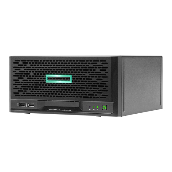
HPE ProLiant MicroServer Gen10 Plus
Maintenance and Service Guide
Abstract
This document contains information on the hardware spare parts supported by the server and the relevant
component replacement procedures. This document is intended for the person who installs, administers, and
troubleshoots server or storage products. Hewlett Packard Enterprise assumes that you are qualified to
service computer equipment, and are trained in recognizing hazards in products with hazardous energy
levels.
Part Number: P19355-001
Published: February 2020
Edition: 1
Advertisement
Table of Contents

Related Manuals for Hewlett Packard Enterprise ProLiant MicroServer Gen10 Plus


Summary of Contents for Hewlett Packard Enterprise ProLiant MicroServer Gen10 Plus
- Page 1 This document is intended for the person who installs, administers, and troubleshoots server or storage products. Hewlett Packard Enterprise assumes that you are qualified to service computer equipment, and are trained in recognizing hazards in products with hazardous energy levels.
- Page 2 Copyright 2020 Hewlett Packard Enterprise Development LP Notices The information contained herein is subject to change without notice. The only warranties for Hewlett Packard Enterprise products and services are set forth in the express warranty statements accompanying such products and services.
-
Page 3: Table Of Contents
Contents Illustrated parts catalog....................6 Mechanical components......................................6 System components........................................6 Heatsink spare part.......................................7 DIMM spare parts......................................7 System battery spare part..................................8 Power cord spare parts....................................8 Power adapter spare part..................................8 Fan spare part........................................8 Riser board spare part....................................9 System board spare part....................................9 Processor spare parts.................................... - Page 4 Removing and replacing the riser board.................................51 Removing and replacing the system board..............................53 Removing the system board.................................53 Replacing the system board................................. 58 Re-entering the server serial number and product ID......................63 System battery replacement....................................64 System battery information.................................. 64 Removing and replacing the system battery..........................64 Removing and replacing the fan..................................66 Removing and replacing the four-bay non-hot-plug drive cable assembly................67 Replacing the external RDX backup system..............................70...
- Page 5 Specifications........................89 Environmental specifications....................................89 Mechanical specifications......................................90 Websites..........................91 Support and other resources..................92 Accessing Hewlett Packard Enterprise Support............................92 ClearCARE technical support....................................92 Accessing updates........................................92 Warranty information......................................... 93 Regulatory information......................................93 Remote support..........................................94 Documentation feedback......................................94...
-
Page 6: Illustrated Parts Catalog
Illustrated parts catalog This chapter lists the hardware spare parts supported by the server. Mechanical components Hewlett Packard Enterprise continually improves and changes product parts. For complete and current supported spare parts information, see the Hewlett Packard Enterprise PartSurfer website: https://www.hpe.com/info/partssurfer... -
Page 7: Heatsink Spare Part
Item Description Heatsink spare part DIMM spare parts System battery spare part Power cord spare parts Power adapter spare part Fan spare part Riser board spare part System board spare part Processor spare parts Four-bay non-hot-plug drive cable assembly spare part* * Not shown Heatsink spare part Customer self repair: mandatory... -
Page 8: System Battery Spare Part
Description Spare part number 8 GB, single-rank x8 PC4-2666V-E P06772-001 16 GB, dual-rank x8 PC4-2666V-E P06773-001 For more information on the removal and replacement procedures, see Removing and replacing a DIMM. System battery spare part Customer self repair: mandatory Description Spare part number 3.3-V, 220-mAh lithium battery coin 319603-001... -
Page 9: Riser Board Spare Part
For more information on the removal and replacement procedures, see Replacing the four-bay non-hot-plug drive cable assembly. Server options Hewlett Packard Enterprise continually improves and changes product parts. For complete and current supported spare parts information, see the Hewlett Packard Enterprise PartSurfer website: https://www.hpe.com/info/partssurfer... -
Page 10: Ilo Enablement Module Spare Part
Item Description iLO enablement module spare part Expansion board For more information on the removal and replacement procedures, see Removing and replacing an expansion board. SFF non-hot-plug solid-state drive For more information on the removal and replacement procedures, see Removing and replacing an SFF drive. -
Page 11: Hpe Trusted Platform Module 2.0 Gen10 Spare Part
For more information on the removal and replacement procedures, see Removing and replacing iLO enablement module. HPE Trusted Platform Module 2.0 Gen10 spare part Customer self repair: no Description Spare part number HPE Trusted Platform Module (TPM) 2.0 Gen10 872159-001 Illustrated parts catalog... -
Page 12: Customer Self Repair
Enterprise (or Hewlett Packard Enterprise service providers or service partners) identifies that the repair can be accomplished by the use of a CSR part, Hewlett Packard Enterprise will ship that part directly to you for replacement. There are two categories of CSR parts: •... - Page 13 (5) jours ouvrés. La pièce et sa documentation doivent être retournées dans l'emballage fourni. Si vous ne retournez pas la pièce défectueuse, Hewlett Packard Enterprise se réserve le droit de vous facturer les coûts de remplacement. Dans le cas d'une pièce CSR, Hewlett Packard Enterprise supporte l'ensemble des frais d'expédition et de retour, et détermine la société...
- Page 14 Per il servizio di garanzia per i soli componenti è obbligatoria la formula CSR che prevede la riparazione da parte del cliente. Se il cliente invece richiede la sostituzione ad Hewlett Packard Enterprise dovrà sostenere le spese di spedizione e di manodopera per il servizio.
- Page 15 Hewlett Packard Enterprise podrá cobrarle por el de sustitución. En el caso de todas sustituciones que lleve a cabo el cliente, Hewlett Packard Enterprise se hará cargo de todos los gastos de envío y devolución de componentes y escogerá la empresa de transporte que se utilice para dicho servicio.
- Page 16 Hewlett Packard Enterprise (ou fornecedores/parceiros da Hewlett Packard Enterprise) concluir que o reparo pode ser efetuado pelo uso de uma peça CSR, a Hewlett Packard Enterprise enviará a peça diretamente ao cliente. Há duas categorias de peças CSR: Obrigatória—Peças cujo reparo feito pelo cliente é...
- Page 17 Serviço de garantia apenas para peças A garantia limitada da Hewlett Packard Enterprise pode incluir um serviço de garantia apenas para peças. Segundo os termos do serviço de garantia apenas para peças, a Hewlett Packard Enterprise fornece as peças de reposição sem cobrar nenhuma taxa.
- Page 18 Customer self repair...
- Page 19 Customer self repair...
- Page 20 Customer self repair...
-
Page 21: Removal And Replacement Procedures
Removal and replacement procedures This chapter provides detailed instructions on how to remove and replace component spare parts. Safety considerations Before performing service procedures, review all the safety information. Electrostatic discharge Be aware of the precautions you must follow when setting up the system or handling components. A discharge of static electricity from a finger or other conductor may damage system boards or other static-sensitive devices. -
Page 22: Server Warnings And Cautions
This symbol on an RJ-45 receptacle indicates a network interface connection. WARNING: To reduce the risk of electric shock, fire, or damage to the equipment, do not plug telephone or telecommunications connectors into this receptacle. This symbol indicates the presence of a hot surface or hot component. If this surface is contacted, the potential for injury exists. -
Page 23: Preparation Procedures
CAUTION: To avoid data loss, Hewlett Packard Enterprise recommends that you back up all server data before installing or removing a hardware option, or performing a server maintenance or troubleshooting procedure. Preparation procedures Power down the server Before powering down the server for any upgrade or maintenance procedures, perform a backup of critical server data and programs. -
Page 24: Removing The System Board Assembly
7. Remove the chassis cover: a. Remove the cover thumbscrews. If the thumbscrews are too tight, use a T-15 Torx screwdriver to remove them (callout 1). b. Slide the cover about half an inch towards the rear panel until the arrowhead markers on the front edge of the chassis are exposed, and then detach the cover from the server (callout 2). - Page 25 5. If the server is in a vertical orientation, position the server in a horizontal orientation. 6. Remove the chassis cover. 7. If a tall internal USB device is installed, remove the device. 8. Remove the system board tray screws. Removal and replacement procedures...
-
Page 26: Installing The System Board Assembly
IMPORTANT: The storage cables connect the system board to the chassis. If you are completely separating the system board assembly from the chassis, disconnect the storage cabling. 9. Use the blue touchpoints on both sides of the tray to pull out the system board assembly from the chassis. Installing the system board assembly Prerequisites Before you perform this procedure, make sure that you have a T-15 Torx screwdriver available. -
Page 27: Installing The Chassis Cover
4. Install the chassis cover. 5. If removed, install the security padlock and/or the Kensington security lock. For more information, see the lock documentation. 6. Connect all peripheral cables to the server. 7. Connect the power adapter to the server, and then secure the power adapter cord in the power cord clip. 8. -
Page 28: Power Up The Server
2. If removed, install the security padlock and/or the Kensington security lock. For more information, see the lock documentation. 3. Connect all peripheral cables to the server. 4. Connect the power adapter to the server, and then secure the power adapter cord in the power cord clip. 5. - Page 29 6. If the front bezel is locked, do the following: a. Remove the chassis cover. b. Switch the bezel locks upward. 7. To remove an unlocked front bezel, do the following: a. Pivot the bottom part of the bezel upward (callout 1). b.
-
Page 30: Removing And Replacing An Lff Drive
To replace the component, reverse the removal procedure. Removing and replacing an LFF drive Prerequisites Before you perform this procedure, make sure that you have a T-15 Torx screwdriver available. Procedure 1. Power down the server. 2. Disconnect the power cord from the AC source. 3. - Page 31 7. Remove the front bezel. 8. Remove the LFF drive: a. Press the drive latch (callout 1). b. Slide the drive out of the drive bay (callout 2). c. Remove the screws from the drive. To replace the component, reverse the removal procedure. Removal and replacement procedures...
-
Page 32: Removing And Replacing An Sff Drive
Removing and replacing an SFF drive Prerequisites Before you perform this procedure, make sure that you have the following items available: • T-10 Torx screwdriver • T-15 Torx screwdriver Procedure 1. Power down the server. 2. Disconnect the power cord from the AC source. 3. - Page 33 c. Remove the screws on the bottom of the converter tray. d. Remove the drive from the converter tray. Removal and replacement procedures...
-
Page 34: Removing And Replacing An Internal Usb Device
To replace the component, reverse the removal procedure. Removing and replacing an internal USB device Procedure 1. Power down the server. 2. Disconnect the power cord from the AC source. 3. Remove the power adapter cord from the power cord clip, and then disconnect the power adapter from the server. 4. -
Page 35: Removing And Replacing A Dimm
To replace the component, reverse the removal procedure. Removing and replacing a DIMM CAUTION: Before replacing a DIMM, expansion board, or other similar PCA components due to a perceived hardware error, make sure first that the component is firmly seated in the slot. Do not bend or flex circuit boards when reseating components. -
Page 36: Removing And Replacing A Heatsink
To replace the component, reverse the removal procedure. Removing and replacing a heatsink Removing a heatsink WARNING: To reduce the risk of personal injury from hot surfaces, allow the drives and the internal system components to cool before touching them. Prerequisites Before you perform this procedure, make sure that you have the following items available: •... - Page 37 Remove the chassis cover. Remove the system board assembly. Allow the heatsink to cool. CAUTION: Heatsink screws must be tightened and loosened in alternating sequence. Do not overtighten the screws as this might damage the system board or the processor socket. 10.
-
Page 38: Replacing A Heatsink
Replacing a heatsink Prerequisites Before you perform this procedure, make sure that you have the following items available: • T-15 Torx screwdriver • Torque screwdriver • Alcohol wipe Procedure Use an alcohol wipe to remove the existing thermal grease from the processor. Allow the alcohol to evaporate before continuing. -
Page 39: Removing And Replacing A Processor
When using a torque wrench, apply 0.56 N⋅m (5.0 lbf-in) of torque to completely tighten the screws. Install the server board assembly. Install the chassis cover. If removed, install the security padlock and/or the Kensington security lock. For more information, see the lock documentation. Connect all peripheral cables to the server. - Page 40 Procedure Power down the server. Disconnect the power cord from the AC source. Remove the power adapter cord from the power cord clip, and then disconnect the power adapter from the server. Disconnect all peripheral cables from the server. If installed, unlock and remove the security padlock and/or the Kensington security lock. For more information, see the lock documentation.
- Page 41 c. Place the heatsink on a flat work surface with its contact side facing upward. 11. Use an alcohol wipe to remove the existing thermal grease from the heatsink. Allow the alcohol to evaporate before continuing. 12. Open the processor load plate: a.
- Page 42 14. Hold the processor by the edges, and then lift it out of the socket. Removal and replacement procedures...
-
Page 43: Replacing A Processor
Replacing a processor Prerequisites Before you perform this procedure, make sure that you have the following items available: • T-15 Torx screwdriver • Torque screwdriver • Alcohol wipe • Thermal grease Procedure CAUTION: THE PINS ON THE PROCESSOR SOCKET AND ON THE PROCESSOR ARE VERY FRAGILE AND EASILY DAMAGED. - Page 44 Install the processor: a. Hold the processor by the edges and align the: • Socket notches with the processor notches • Pin 1 indicator on the processor and the socket b. Lower the processor straight down, without tilting or sliding the processor in the socket . Make sure that the processor is properly seated in the socket.
- Page 45 CAUTION: To prevent thermal failure or component damage, do not move the heatsink once the bottom of its base plate touches the top of the processor. Excessive heatsink movement can cause the thermal grease to smear and become uneven. Voids in the compound can adversely impact the transfer of heat away from the processor. CAUTION: Heatsink screws must be tightened and loosened in alternating sequence.
-
Page 46: Removing And Replacing The Ilo Enablement Module
If removed, install the security padlock and/or the Kensington security lock. For more information, see the lock documentation. Connect all peripheral cables to the server. 10. Connect the power adapter to the server, and then secure the power adapter cord in the power cord clip. 11. - Page 47 Remove the chassis cover. Remove the system board assembly. Remove the screw on the rear panel (callout 1), and then remove the iLO enablement module (callout 2). 10. Remove the module screws (callout 1), and then separate the iLO enablement module from its bracket (callout 2). Removal and replacement procedures...
-
Page 48: Removing And Replacing An Expansion Board
To replace the component, reverse the removal procedure. Removing and replacing an expansion board CAUTION: To prevent improper cooling and thermal damage, do not operate the server unless all PCI slots have either an expansion slot cover or an expansion board installed. IMPORTANT: Before replacing a DIMM, expansion board, or any other circuit board component due to a perceived hardware error, verify that the component is firmly seated in the slot. -
Page 49: Remove The Air Baffle From The Expansion Board
Remove the chassis cover. Remove the system board assembly. Disconnect any internal cables that are connected to the expansion board. 10. Remove the expansion board. To replace the component, reverse the removal procedure. If the new expansion board is shipped with an air baffle attached, remove this baffle from the board. If the new expansion board is shipped with a full-height bracket attached, remove the bracket from the board and replace it with a low-profile bracket. -
Page 50: Install A Low-Profile Bracket On The Expansion Board
Install a low-profile bracket on the expansion board The number and location of the bracket screws will vary depending on the expansion board. The illustrations below are example images only. See the expansion board documentation for model-specific information. Procedure 1. Remove the full-height bracket from the expansion board. 2. -
Page 51: Removing And Replacing The Riser Board
Removing and replacing the riser board CAUTION: Before replacing a DIMM, expansion board, or other similar PCA components due to a perceived hardware error, make sure first that the component is firmly seated in the slot. Do not bend or flex circuit boards when reseating components. - Page 52 Remove the chassis cover. Remove the system board assembly. If installed, remove the iLO enablement module screw (callout 1), and then remove the module (callout 2). 10. If installed, remove the expansion board from the riser. 11. Remove the riser board: a.
-
Page 53: Removing And Replacing The System Board
12. Separate the riser board from its bracket. To replace the component, reverse the removal procedure. Removing and replacing the system board Removing the system board WARNING: To reduce the risk of personal injury from hot surfaces, allow the drives and the internal system components to cool before touching them. - Page 54 Disconnect all peripheral cables from the server. If installed, unlock and remove the security padlock and/or the Kensington security lock. For more information, see the lock documentation. If the server is in a vertical orientation, position the server in a horizontal orientation. Remove the chassis cover.
- Page 55 12. Remove all DIMMs. 13. Remove the riser board: a. Remove the riser screw on the rear panel (callout 1). b. Loosen the screws on the base of the riser (callout 2). c. Remove the riser board from the system board (callout 3). 14.
- Page 56 c. Place the heatsink on a flat work surface with its contact side facing upward. 15. Use an alcohol wipe to remove the existing thermal grease from the heatsink and the top of the processor. Allow the alcohol to evaporate before continuing. 16.
- Page 57 18. Hold the processor by the edges, and then lift it out of the socket. 19. Remove the system board: Removal and replacement procedures...
-
Page 58: Replacing The System Board
a. Remove the system board screws (callout 1). b. Remove the system board from its tray (callout 2). Replacing the system board Prerequisites Before you perform this procedure, make sure that you have the following items available: • T-15 Torx screwdriver •... - Page 59 Open the processor load plate: a. Push the processor locking lever down to unclip, and then lift it upwards (callout 1). b. Open the processor load plate (callout 2). CAUTION: THE PINS ON THE PROCESSOR SOCKET AND ON THE PROCESSOR ARE VERY FRAGILE AND EASILY DAMAGED.
- Page 60 Remove the processor socket cover. Install the processor: a. Hold the processor by the edges and align the: Removal and replacement procedures...
- Page 61 • Socket notches with the processor notches • Pin 1 indicator on the processor and the socket b. Lower the processor straight down, without tilting or sliding the processor in the socket . Make sure that the processor is properly seated in the socket. CAUTION: The processor load plate and locking lever should close without resistance.
- Page 62 CAUTION: To prevent thermal failure or component damage, do not move the heatsink once the bottom of its base plate touches the top of the processor. Excessive heatsink movement can cause the thermal grease to smear and become uneven. Voids in the compound can adversely impact the transfer of heat away from the processor. CAUTION: Heatsink screws must be tightened and loosened in alternating sequence.
-
Page 63: Re-Entering The Server Serial Number And Product Id
• DIMMs • Riser board 10. If the following server options were removed, install them back: • Expansion board • iLO enablement module • Internal USB device 11. Install the server board assembly. 12. Install the chassis cover. 13. If removed, install the security padlock and/or the Kensington security lock. For more information, see the lock documentation. -
Page 64: System Battery Replacement
7. Type the product ID and press Enter. 8. Press F10 to save the configuration. The procedure is complete. System battery replacement System battery information The server contains an internal lithium manganese dioxide, a vanadium pentoxide, or an alkaline battery that provides power to the real-time clock. - Page 65 Remove the chassis cover. Remove the system board assembly. Locate the battery on the system board. Remove the system battery: a. Use a small flat-bladed, nonconductive tool to press the battery latch (callout 1). b. Remove the system battery from the socket (callout 2). 10.
-
Page 66: Removing And Replacing The Fan
11. Install the server board assembly. 12. Install the chassis cover. 13. If removed, install the security padlock and/or the Kensington security lock. For more information, see the lock documentation. 14. Connect all peripheral cables to the server. 15. Connect the power adapter to the server, and then secure the power adapter cord in the power cord clip. 16. -
Page 67: Removing And Replacing The Four-Bay Non-Hot-Plug Drive Cable Assembly
7. Remove the chassis cover. 8. Remove the system board assembly. 9. Remove the fan: a. Disconnect the fan cable. b. Remove the fan screws (callout 1), and then remove the fan (callout 2). To replace the component, reverse the removal procedure. Removing and replacing the four-bay non-hot-plug drive cable assembly IMPORTANT: The four-bay non-hot-plug drive cable assembly consists of the drive and ambient sensor cables. - Page 68 Prerequisites Before you perform this procedure, make sure that you have a T-15 Torx screwdriver available. Procedure Power down the server. Disconnect the power cord from the AC source. Remove the power adapter cord from the power cord clip, and then disconnect the power adapter from the server. Disconnect all peripheral cables from the server.
- Page 69 c. Pull out the drive cable assembly from the cable channel under the drive bay 4. 13. Separate the drive cable assembly from its bracket: a. Remove the cable assembly screws. Removal and replacement procedures...
-
Page 70: Replacing The External Rdx Backup System
If you suspect a TPM board failure, leave the TPM installed and remove the system board (Removing the system board). Contact a Hewlett Packard Enterprise authorized service provider for a replacement system board and TPM board. Removal and replacement procedures... -
Page 71: Troubleshooting
Integrated Management Log Messages and Troubleshooting Guide for HPE ProLiant Gen10 and HPE Synergy provides IML messages and associated troubleshooting information to resolve critical and cautionary IML events. To access the troubleshooting resources, see the Hewlett Packard Enterprise Information Library (https://www.hpe.com/ info/gen10-troubleshooting). -
Page 72: Diagnostic Tools
Product QuickSpecs For more information about product features, specifications, options, configurations, and compatibility, see the product QuickSpecs on the Hewlett Packard Enterprise website (https://www.hpe.com/info/qs). UEFI System Utilities The UEFI System Utilities is embedded in the system ROM. Its features enable you to perform a wide range of configuration activities, including: •... -
Page 73: Secure Boot
Using the System Utilities options described in the following sections. • • Using the iLO RESTful API to clear and restore certificates. For more information, see the Hewlett Packard Enterprise website (https://www.hpe.com/info/redfish). • Using the secboot command in the Embedded UEFI Shell to display Secure Boot databases, keys, and security reports. -
Page 74: Intelligent Provisioning
NOTE: After you have selected a mode, you must reprovision the server to change the mode that launches when you boot to F10. Intelligent Provisioning prepares the system for installing original, licensed vendor media and Hewlett Packard Enterprise- branded versions of OS software. Intelligent Provisioning also prepares the system to integrate optimized server support software from the Service Pack for ProLiant (SPP). -
Page 75: Hpe Insight Remote Support
Hewlett Packard Enterprise, which will initiate a fast and accurate resolution, based on your product’s service level. Notifications can be sent to your authorized Hewlett Packard Enterprise Channel Partner for onsite service, if configured and available in your country. -
Page 76: Usb Support
For more information on getting started and using HPE InfoSight for servers, go to: https://www.hpe.com/info/ infosight-servers-docs. USB support Hewlett Packard Enterprise Gen10 and Gen10 Plus servers support all USB operating speeds depending on the device that is connected to the server. External USB functionality Hewlett Packard Enterprise provides external USB support to enable local connection of USB devices for server administration, configuration, and diagnostic procedures. -
Page 77: Component Identification
Component identification This chapter describes the external and internal server features and components. Front panel components Item Component Description Drive bays (4, behind the front bezel) By default, the drive bays support 3.5-inch LFF SATA drives. To support 2.5-inch SFF drives, install the SFF drive converter option. -
Page 78: Front Panel Leds And Button
Front panel LEDs and button Item Description Status Definition Drive activity LED Flashing green Ongoing drive activity No drive activity 2, 3 NIC status LED Solid green Linked to network Flashing green Network active No network activity Health LED Solid green Normal Flashing green iLO is rebooting... -
Page 79: Rear Panel Components
Subsystem LED behavior System board 1 flash Processor 2 flashes Memory 3 flashes Riser board PCIe slots 4 flashes FlexibleLOM 5 flashes Removable HPE Smart Array SR Gen10 controller 6 flashes System board PCIe slots 7 flashes Power backplane or storage backplane 8 flashes Power supply 9 flashes... -
Page 80: Rear Panel Leds
Item Component Description System QR code label To access the server mobile product page (https://www.hpe.com/ qref/microservergen10plus), use a QR code scanner app in your smartphone to scan this label. This mobile page contains links to server setup information, spare part numbers, QuickSpecs, troubleshooting resources, and other useful product links. -
Page 81: System Board Components
Item Status Definition NIC status Solid green Linked to network Flashing green Network active No network activity System board components Item Component Description TPM connector This connector supports the HPE Trusted Platform Module 2.0 Gen10 option (864279-B21) for data security. Fan connector Connects the fan cable. -
Page 82: System Maintenance Switch Descriptions
System maintenance switch descriptions Position Default Function Off = iLO 5 security is enabled. On = iLO 5 security is disabled. Reserved Reserved Reserved Off = Power-on password is enabled. On = Power-on password is disabled. 1, 2, 3 Off = No function On = Restore default manufacturing settings Reserved —... - Page 83 Item Description Example Capacity 8 GB 16 GB 32 GB 64 GB 128 GB Rank 1R = Single rank 2R = Dual rank 4R = Quad rank 8R = Octal rank Data width on DRAM x4 = 4-bit x8 = 8-bit x16 = 16-bit Memory generation PC4 = DDR4...
-
Page 84: Drive Bay Numbering
For more information about product features, specifications, options, configurations, and compatibility, see the HPE DDR4 SmartMemory QuickSpecs on the Hewlett Packard Enterprise website (https://www.hpe.com/support/ DDR4SmartMemoryQS). Drive bay numbering Drive screws There are 16 T-15 Torx screws located under the drive bays. Use these screws to install drives in the server. -
Page 85: Riser Board Slots
Riser board slots Item Description Supported option iLO dedicated network module slot Install the iLO enablement option here. PCIe3 ×16 expansion slot Install a half-height PCIe3 ×16 expansion board here. See the product QuickSpecs on the server website at https:// www.hpe.com/servers/microserver for list of supported expansion options. -
Page 86: Cabling
Cabling Cabling overview This section provides guidelines that help you make informed decisions about cabling the server and hardware options to optimize performance. CAUTION: When routing cables, always be sure that the cables are not in a position where they can be pinched or crimped. -
Page 87: Four-Bay Drive Cabling: Smart Array Controller Cabling
Four-bay drive cabling: Smart Array controller cabling IMPORTANT: The four-bay non-hot-plug drive cable assembly consists of the drive and ambient sensor cables. If any of these cables becomes defective, the entire cable assembly will need to be replaced. Cable color Description Orange Drive power cable... -
Page 88: Fan Cabling
Fan cabling Cabling... -
Page 89: Specifications
900 m (2953 ft) to a maximum of 3050 m (10,000 ft). The approved hardware configurations for this system are listed at the Hewlett Packard Enterprise website. 40°C to 45°C (104°F to 113°F) at sea level with an altitude derating of 1.0°C per every 125 m (1.8°F per every 410 ft) above 900 m (2953 ft) to a maximum of 3050 m (10,000 ft). -
Page 90: Mechanical Specifications
Mechanical specifications Dimension Value Height 11.89 cm (4.68 in) Depth 24.50 cm (9.65 in) Width 24.50 cm (9.65 in) Weight, minimum (one drive and one DIMM installed, no iLO 4.82 kg (10.63 lb) enablement module or expansion board installed) Weight, maximum (four drives, two DIMMs, iLO enablement 7.20 kg (15.87 lb) module, and an expansion board installed) Specifications... -
Page 91: Websites
Storage white papers and analyst reports https://www.hpe.com/storage/whitepapers For additional websites, see Support and other resources. Product websites HPE ProLiant MicroServer Gen10 Plus product page https://www.hpe.com/servers/microserver HPE ProLiant MicroServer Gen10 Plus support page https://www.hpe.com/support/microservergen10plus HPE ProLiant MicroServer Gen10 Plus user documents https://www.hpe.com/info/microservergen10plus-docs... -
Page 92: Support And Other Resources
Third-party products or components ClearCARE technical support Support for ClearOS and ClearVM is not provided by Hewlett Packard Enterprise. Support for ClearOS and ClearVM is purchased and delivered by ClearCenter. You can purchase single support incidents by submitting a support ticket to ClearCenter, or you can purchase a Bronze, Silver, Gold, or Platinum ClearCARE subscription. -
Page 93: Warranty Information
Additional regulatory information Hewlett Packard Enterprise is committed to providing our customers with information about the chemical substances in our products as needed to comply with legal requirements such as REACH (Regulation EC No 1907/2006 of the European Parliament and the Council). A chemical information report for this product can be found at: https://www.hpe.com/info/reach... -
Page 94: Remote Support
Documentation feedback Hewlett Packard Enterprise is committed to providing documentation that meets your needs. To help us improve the documentation, send any errors, suggestions, or comments to Documentation Feedback (docsfeedback@hpe.com). When submitting your feedback, include the document title, part number, edition, and publication date located on the front cover of the document.
Need help?
Do you have a question about the ProLiant MicroServer Gen10 Plus and is the answer not in the manual?
Questions and answers