Table of Contents
Advertisement
Quick Links
HPE ProLiant XL190r Gen10 Server User
Guide
Abstract
This document is for the person who installs, administers, and troubleshoots servers and
storage systems. Hewlett Packard Enterprise assumes you are qualified in the servicing of
computer equipment and trained in recognizing hazards in products with hazardous energy
levels.
Part Number: 879110-006
Published: August 2019
Edition: 6
Advertisement
Table of Contents

Related Manuals for Hewlett Packard Enterprise ProLiant XL190r Gen10


Summary of Contents for Hewlett Packard Enterprise ProLiant XL190r Gen10
- Page 1 Abstract This document is for the person who installs, administers, and troubleshoots servers and storage systems. Hewlett Packard Enterprise assumes you are qualified in the servicing of computer equipment and trained in recognizing hazards in products with hazardous energy levels.
- Page 2 Packard Enterprise products and services are set forth in the express warranty statements accompanying such products and services. Nothing herein should be construed as constituting an additional warranty. Hewlett Packard Enterprise shall not be liable for technical or editorial errors or omissions contained herein.
-
Page 3: Table Of Contents
Contents Introduction..................... 7 Component identification...............8 Rear panel components........................8 Serial number/iLO information pull tab................8 Rear panel LEDs and buttons.......................9 Server UID LED........................10 UID button functionality....................10 Front panel LED power fault codes.................. 11 HPE InfiniBand HDR/Ethernet 940QSFP 56x16 adapter LEDs........11 System board components...................... - Page 4 Product QuickSpecs........................42 Compiling the documentation..................... 42 Initial server installation.......................43 HPE Installation Service....................43 Setting up the server......................43 Installing the operating system with the HPE Smart Array MR Gen10 P824i-p controller driver.........................46 Operational requirements......................46 Site requirements......................47 Space and airflow requirements..................47 Temperature requirements....................
- Page 5 Accelerator options installation..................90 Installing an accelerator....................90 M.2 SATA SSD option......................... 95 Installing an M.2 SSD.......................96 Installing the Omni-Path Architecture adapter option..............97 Installing the Media Module adapter..................100 HPE Trusted Platform Module 2.0 Gen10 option..............102 Overview........................102 HPE Trusted Platform Module 2.0 Guidelines..............102 Installing and enabling the HPE TPM 2.0 Gen10 Kit.............
- Page 6 Performance feature enabled..................137 Thermal limitations for components in systems with the Enhanced Processor Performance feature disabled..................158 Websites....................178 Support and other resources.............179 Accessing Hewlett Packard Enterprise Support............... 179 Accessing updates........................179 Customer self repair........................180 Remote support........................180 Warranty information.........................180 Regulatory information......................181 Documentation feedback......................
-
Page 7: Introduction
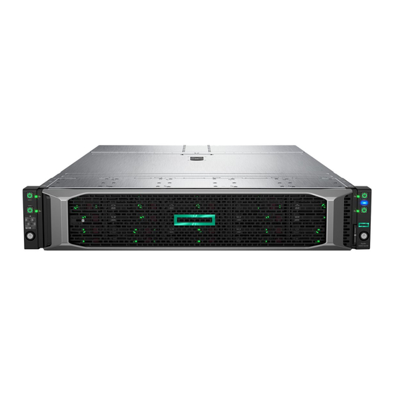
Introduction The HPE ProLiant XL190r Gen10 server is a 2U half-width server that contains two processors. The configuration options are same as the HPE ProLiant XL170r Gen10 server for CPU and memory. The server has additional PCIe slots in multiple configurations and supports additional expansion cards and two accelerators per server. -
Page 8: Component Identification
Component identification Rear panel components Item Description Slot 3 PCIe3 x16 (16, 8, 4, 1) Slot 1 PCIe3 x16 (16, 8, 4, 1) Slot 2 PCIe3 x16 (16, 8, 4, 1) or FlexibleLOM SUV port iLO Management Port iLO Service Port Serial number/iLO information pull tab on page 8 USB 3.0 port Media Module NIC port 1... -
Page 9: Rear Panel Leds And Buttons
Rear panel LEDs and buttons Item Status Definition NIC link LED Green Linked to network No network link NIC status LED Flashing green Network active No network activity Power On/Standby button Solid green System on and normal operation and system power LED Flashing green Performing power-on sequence Solid amber... -
Page 10: Server Uid Led
UID button functionality The UID button can be used to display the Server Health Summary when the server will not power on. For more information, see the latest HPE iLO 5 User Guide on the Hewlett Packard Enterprise website. Component identification... -
Page 11: Front Panel Led Power Fault Codes
Front panel LED power fault codes The following table provides a list of power fault codes, and the subsystems that are affected. Not all power faults are used by all servers. Subsystem LED behavior System board 1 flash Processor 2 flashes Memory 3 flashes Riser board PCIe slots... -
Page 12: System Board Components
System board components Item Description Primary PCIe x16 riser connector 1 Media Module connector System battery OPA adapter sideband cable connector M.2 SSD riser connector Processor 1 DIMM slots for processor 1 Processor 2 DIMM slots for processor 2 Bayonet board connector Secondary PCIe x24 riser connector 4 Secondary PCIe x24 riser connector 3 x4 SATA port... -
Page 13: System Maintenance Switch Descriptions
System maintenance switch descriptions Position Default Function Off = iLO 5 security is enabled. On = iLO 5 security is disabled. Reserved Reserved Reserved Off = Power-on password is enabled. On = Power-on password is disabled. 1, 2, 3 Off = No function On = Restore default manufacturing settings Reserved —... - Page 14 Item Description Example Capacity 8 GB 16 GB 32 GB 64 GB 128 GB Rank 1R = Single rank 2R = Dual rank 4R = Quad rank 8R = Octal rank Data width on DRAM x4 = 4-bit x8 = 8-bit x16 = 16-bit Memory generation PC4 = DDR4...
-
Page 15: Hpe Persistent Memory Module Label Identification
For more information about product features, specifications, options, configurations, and compatibility, see the HPE DDR4 SmartMemory QuickSpecs on the Hewlett Packard Enterprise website (http:// www.hpe.com/support/DDR4SmartMemoryQS). HPE Persistent Memory module label identification Item Description Example Unique ID number 8089-A2-1802-1234567 Model number... -
Page 16: Processor, Heatsink, And Socket Components
Processor, heatsink, and socket components Item Description Heatsink nuts Processor carrier Pin 1 indicator Heatsink latch Alignment post Symbol also on the processor and frame. Bayonet board components Item Description Bayonet port 1 Bayonet port 2 Bayonet port 3 Table Continued Component identification... -
Page 17: Pcie Riser Board Components
Item Description Bayonet port 4 GPU auxiliary power cable connector PCIe riser board components This section identifies the riser slots compatible with specific types of expansion options supported by the server. The following riser options are supported: • Primary riser •... - Page 18 Three-slot secondary riser board components Three-slot secondary riser slots Item Slot number Description Supported options PCIe3 x16 (16, 8, 4, 1) • PCIe workload accelerator • Computation and graphics accelerator — Storage controller backup power — connector PCIe3 x16 (16, 8, 4, 1) •...
- Page 19 Three-slot secondary riser port numbering FlexibleLOM riser board components FlexibleLOM riser slots Item Slot number Description Supported options PCIe3 x16 (16, 8, 4, 1) • PCIe workload accelerator • Computation and graphics accelerator PCIe3 x16 (16, 8, 4, 1) — FlexibleLOM slot PCIe3 x16 (16, 8, 4, 1) FlexibleLOM adapter...
- Page 20 The transfer board is, by default, installed on the secondary riser slot 3. FlexibleLOM riser port numbering M.2 SSD riser bay numbering The arrow points toward the server release lever. Item Description Bay 7 Bay 8 Component identification...
-
Page 21: Accelerator Numbering
Accelerator numbering HPE Smart Array P824i-p MR Gen10 Controller Components Item Description Internal SAS port 1i Internal SAS port 2i Internal SAS port 3i Internal SAS port 4i Controller backup power cable connector Table Continued Component identification... -
Page 22: Hpe Infiniband Hdr100/Ethernet 200 Gb 1-Port 940Qsfp56 X16 Adapter Component
Item Description Internal SAS port 5i Internal SAS port 6i HPE InfiniBand HDR100/Ethernet 200 GB 1-port 940QSFP56 x16 adapter component Item Description QSFP56 port Black cable connector Black cable connector HPE InfiniBand HDR PCIe G3 Auxiliary card Item Description Black cable connector Black cable connector Component identification... -
Page 23: Operations
Operations This chapter describes the hardware operations carried out prior to and after installing or removing a hardware option, or performing a server maintenance or troubleshooting procedure. Before performing these hardware operations, review and observe the server warnings and cautions. Power up the server The SL/XL chassis firmware initiates an automatic power-up sequence when the servers are installed. - Page 24 Prerequisites See the Locations of drive blanks and thermal bezel blanks for components with thermal limitations on page 25 to: 1. Identify the chassis model and system fan mode of the system you plan to install the component in. 2. Determine if the accelerator is subject to thermal limitations in the identified system setup. 3.
-
Page 25: Locations Of Drive Blanks And Thermal Bezel Blanks For Components With Thermal Limitations
• Install the SFF drive blanks. Locations of drive blanks and thermal bezel blanks for components with thermal limitations Apollo r2200 Gen10 Chassis in nonredundant/redundant fan mode The illustration callouts: • outside the front panel image refer to the server numbering. •... - Page 26 Accelerator model Required drive bay action Tesla P100 12 GB LFF thermal bezel blanks in bays: Tesla P100 16 GB 1-9, 1-10, 1-11 Tesla V100 16 GB 3-9, 3-10, 3-11 Tesla V100 32 GB Tesla P4 LFF drive blanks in bays: Tesla P40 24 GB 1-2, 1-10 Tesla M10 Quad...
- Page 27 Accelerator model Required drive bay action Tesla P100 12 GB SFF thermal bezel blanks in bays: Tesla P100 16 GB 1-9, 1-10, 1-11, 1-12, 1-13, 1-14 Tesla V100 16 GB 3-9, 3-10, 3-11, 3-12, 3-13, 3-14 Tesla V100 32 GB InfiniBand adapter model Required drive bay action IB HDR100/EN 100 GB 1P...
-
Page 28: Remove The Server From The Chassis
Accelerator model Required drive bay action Tesla V100 16 GB, nonredundant SFF drive blanks in bays: fan mode 2-1, 2-2, 2-3, 2-4 4-1, 4-2, 4-3, 4-4 Tesla V100 32 GB, nonredundant SFF thermal bezel blanks in bays: or redundant fan mode 1-3, 1-4, 2-1, 2-2, 2-3, 2-4 3-3, 3-4, 4-1, 4-2, 4-3, 4-4 InfiniBand adapter model... -
Page 29: Install The Server Into The Chassis
Install the server into the chassis CAUTION: To avoid damage to the server or server blank: • Always support the bottom of the server or server blank when removing it from the chassis. • Do not use the release lever to carry the server or server blank. Procedure 1. -
Page 30: Remove The Bayonet Board
4. Connect all peripheral cables to the server. 5. Power up the server on page 23. Remove the bayonet board Prerequisites Before you perform this procedure, make sure that you have a T-10 Torx screwdriver available. Procedure 1. Power down the server on page 23. 2. -
Page 31: Install The Bayonet Board
c. Disconnect the bayonet board cables, and then remove the bayonet board. Install the bayonet board Prerequisites Before you perform this procedure, make sure that you have a T-10 Torx screwdriver available. Procedure 1. Install the bayonet board: a. Connect all the bayonet board cables. b. - Page 32 c. Install the bayonet board cover, and then and install the screws to secure it to the server tray. d. Install the screws to secure the cover to the bayonet board. Operations...
-
Page 33: Remove The Secondary Riser Cage
2. Install the server into the chassis on page 29. 3. Connect all peripheral cables to the server. 4. Power up the server on page 23. Remove the secondary riser cage Prerequisites Before you perform this procedure, make sure that you have a T-10 Torx screwdriver available. Procedure 1. -
Page 34: Install The Secondary Riser Cage
Install the secondary riser cage Prerequisites Before you perform this procedure, make sure that you have a T-10 Torx screwdriver available. Procedure 1. Install the secondary riser cage. Make sure that the riser board is firmly seated in its system board connectors. -
Page 35: Remove The Primary Riser Blank
Remove the primary riser blank CAUTION: To prevent improper cooling and thermal damage, do not operate the server unless either riser blank or the riser cage is installed. Prerequisites Before you perform this procedure, make sure that you have a T-10 Torx screwdriver available. Procedure 1. -
Page 36: Remove The Primary Riser Cage
2. Install the secondary riser cage on page 34. 3. Install the bayonet board on page 31. 4. Install the server into the chassis on page 29. 5. Connect all peripheral cables to the server. 6. Power up the server on page 23. Remove the primary riser cage CAUTION: To prevent improper cooling and thermal damage, do not operate the server unless either riser blank or the riser cage is installed. -
Page 37: Install The Primary Riser Cage
Install the primary riser cage Prerequisites Before you perform this procedure, make sure that you have a T-10 Torx screwdriver available. Procedure 1. Install the primary riser cage. Make sure that the riser board is firmly seated in its system board the connector. -
Page 38: Remove The Secondary Riser Cage Thermal Brackets
5. Connect all peripheral cables to the server. 6. Power up the server on page 23. Remove the secondary riser cage thermal brackets CAUTION: To prevent improper cooling and thermal damage, do not operate the server unless the correct thermal brackets are installed. Prerequisites Before you perform this procedure, make sure that you have a T-10 Torx screwdriver available. -
Page 39: Install The Secondary Riser Thermal Brackets
3. Remove the riser slot 4 thermal bracket. 4. Remove the side bracket. Install the secondary riser thermal brackets Prerequisites Before you perform this procedure, make sure that you have a T-10 Torx screwdriver available. Procedure 1. Install the riser slot 4 thermal bracket. Operations... - Page 40 2. Install the side bracket. 3. Install the middle thermal bracket. Operations...
- Page 41 4. Install the rear thermal bracket. Operations...
-
Page 42: Setup
HPE ProLiant systems. Hewlett Packard Enterprise support services let you integrate both hardware and software support into a single package. A number of service level options are available to meet your business and IT needs. -
Page 43: Initial Server Installation
Verify that your OS or virtualization software is supported: http://www.hpe.com/info/ossupport • Read the HPE UEFI requirements for ProLiant servers on the Hewlett Packard Enterprise website. If the UEFI requirements are not met, you might experience boot failures or other errors when installing the operating system. - Page 44 http://www.hpe.com/support/safety-compliance-enterpriseproducts • Read the system operational requirements and the server warnings and cautions: ◦ Operational requirements on page 46 ◦ Server warnings and cautions on page 48 Procedure Unbox the server node and verify the contents: • Server node • Documentation (Optional) Install the server hardware options.
- Page 45 Using the SPP, update the following: • System ROM • Storage controller • Network controller Set up the storage 10. Set up the storage. Do one of the following: • To configure the server to boot from a SAN, see the following guide: https://www.hpe.com/info/boot-from-san-config-guide •...
-
Page 46: Installing The Operating System With The Hpe Smart Array Mr Gen10 P824I-P Controller Driver
From the boot screen, press F9 to run UEFI System Utilities. From the UEFI System Utilities screen, select System Configuration > Embedded Storage: HPE Smart Storage S100i SR Gen10 > Array Configuration > Create Array. Deploy an OS or virtualization software 11. -
Page 47: Site Requirements
Leave a minimum clearance of 121.9 cm (48 in) from the back of the rack to the back of another rack or row of racks. Hewlett Packard Enterprise servers draw in cool air through the front door and expel warm air through the rear door. Therefore, the front and rear rack doors must be adequately ventilated to allow ambient room air to enter the cabinet, and the rear door must be adequately ventilated to allow the warm air to escape from the cabinet. -
Page 48: Power Requirements
CAUTION: To reduce the risk of damage to the equipment when installing third-party options: • Do not permit optional equipment to impede airflow around the server or to increase the internal rack temperature beyond the maximum allowable limits. • Do not exceed the manufacturer’s TMRA. Power requirements Installation of this equipment must comply with local and regional electrical regulations governing the installation of IT equipment by licensed electricians. - Page 49 Improper grounding can cause electrostatic discharge. For more information, refer to "Electrostatic discharge on page 50." CAUTION: To avoid data loss, Hewlett Packard Enterprise recommends that you back up all server data before installing or removing a hardware option, or performing a server maintenance or troubleshooting procedure.
-
Page 50: Electrostatic Discharge
CAUTION: Do not operate the server for long periods with the access panel open or removed. Operating the server in this manner results in improper airflow and improper cooling that can lead to thermal damage. Electrostatic discharge Be aware of the precautions you must follow when setting up the system or handling components. A discharge of static electricity from a finger or other conductor may damage system boards or other static- sensitive devices. - Page 51 For more information on automatic configuration, see the UEFI documentation on the Hewlett Packard Enterprise website. Setup...
-
Page 52: Hardware Options Installation
Hardware options installation Introduction Install any hardware options before initializing the server. For options installation information, see the option documentation. For server-specific information, use the procedures in this section. If multiple options are being installed, read the installation instructions for all the hardware options to identify similar steps and streamline the installation process. -
Page 53: Using An Suv Cable To Access Usb Drives In A Kvm Setup
Using an SUV cable to access USB drives in a KVM setup The USB connectors on the SUV cable do not support USB devices that require a power source greater than 500 mA at 5 V. When accessing this type of USB drives, such as a USB key or a USB optical drive, use a USB hub in a KVM setup. -
Page 54: Processor Cautions
CAUTION: If installing a processor with a faster speed, update the system ROM before installing the processor. To download firmware and view installation instructions, see the Hewlett Packard Enterprise Support Center website. CAUTION: THE CONTACTS ARE VERY FRAGILE AND EASILY DAMAGED. To avoid damage to the socket or processor, do not touch the contacts. - Page 55 Retain the blank for future use. Install the processor heatsink assembly: a. Locate and align the Pin 1 indicator on the processor frame and the socket. b. Align the processor heatsink assembly with the heatsink alignment posts and gently lower it down until it sits evenly on the socket.
-
Page 56: Selecting An Advanced Fan Cooling Method
Install the secondary riser cage on page 34. 10. Install the bayonet board on page 31. 11. Install the server into the chassis on page 29. 12. Connect all peripheral cables to the server. 13. Power up the server on page 23. 14. -
Page 57: Dimm Population Information
Mixing DIMM types is not supported. Install either all DDR4-2666 DIMMs or all DDR4-2933 DIMMs in the server. HPE SmartMemory speed information For more information about memory speed information, see the Hewlett Packard Enterprise website (https://www.hpe.com/docs/memory-speed-table). Installing a DIMM The server supports up to 16 DIMMs. -
Page 58: Hpe Persistent Memory Option
The DIMM slots are structured to ensure proper installation. If you try to insert a DIMM but it does not fit easily into the slot, you might have positioned it incorrectly. Reverse the orientation of the DIMM and insert it again. Install the secondary riser cage on page 34. -
Page 59: Hpe Persistent Memory Population Information
Server Platform Services (SPS) Firmware version 04.01.04.296 ◦ HPE iLO 5 Firmware version 1.43 ◦ HPE Innovation Engine Firmware version 2.1.x or later Download the required firmware and drivers from the Hewlett Packard Enterprise website (http:// www.hpe.com/info/persistentmemory). • A supported operating system: ◦... -
Page 60: Installing Hpe Persistent Memory Modules
For more information, see the HPE Persistent Memory User Guide on the Hewlett Packard Enterprise website (http://www.hpe.com/info/persistentmemory-docs). Installing HPE Persistent Memory modules Use this procedure only for new HPE Persistent Memory module installations. If you are migrating this HPE Persistent Memory module from another server, see the HPE Persistent Memory User Guide on the Hewlett Packard Enterprise website (http://www.hpe.com/info/persistentmemory-docs). -
Page 61: Configuring The Server For Hpe Persistent Memory
HPE Persistent Memory, as well as evaluate and monitor the server memory configuration layout. For more information, see the HPE Persistent Memory User Guide on the Hewlett Packard Enterprise website (http://www.hpe.com/info/persistentmemory-docs). Riser cage options Installing the primary riser cage option The primary riser function is linked to processor 1. -
Page 62: Installing The Secondary Riser Cage Option
Prerequisites Before installing this option, make sure that you have a T-15 Torx screwdriver available. Procedure Power down the server on page 23. Disconnect all peripheral cables from the server. Remove the server from the chassis on page 28. Remove the bayonet board on page 30. Remove the secondary riser cage on page 33. - Page 63 Procedure Power down the server on page 23. Disconnect all peripheral cables from the server. Remove the server from the chassis on page 28. Remove the bayonet board on page 30. If you are planning to install an expansion board in this riser cage, install it now. Install the rear thermal bracket.
-
Page 64: Flexiblelom Option
Install the secondary riser cage. Make sure that the riser board is firmly seated in its system board connectors. 10. Connect the secondary riser cables to the bayonet board. 11. Install the bayonet board on page 31. 12. Install the server into the chassis on page 29. 13. -
Page 65: Installing The Flexiblelom Adapter
Installing the FlexibleLOM adapter CAUTION: The maximum inlet ambient temperature for most components installed in the system is 35°C (95°F). Some components, however, are subject to thermal limitations depending on the chassis model and the fan configuration. There are some hardware configurations where it is necessary to limit the number of drives installed in the chassis. -
Page 66: Expansion Board Options
Install the FlexibleLOM riser cage. 10. Install the bayonet board on page 31. 11. Install the server into the chassis on page 29. 12. Connect the LAN segment cables to the adapter. 13. Connect all peripheral cables to the server. 14. - Page 67 Remove the secondary riser cage on page 33. Remove the primary riser cage on page 36. Remove the primary riser slot blank. If installed, remove the full-height bracket from the expansion board. Install the low-profile bracket on the expansion board. Hardware options installation...
- Page 68 10. Make sure that any switches or jumpers on the expansion board are set properly. For more information, see the documentation that ships with the option. 11. Connect all necessary internal cabling to the expansion board. For more information on these cabling requirements, see the documentation that ships with the option.
-
Page 69: Installing An Expansion Board In The Secondary Riser Cage
Installing an expansion board in the secondary riser cage The server supports multiple riser options in the secondary position. Processor 2 is required to support these secondary riser options. For more information on the secondary riser options, see Secondary riser board component. - Page 70 c. Make sure that any switches or jumpers on the expansion board are set properly. For more information, see the documentation that ships with the option. d. Lay the secondary riser cage on its side with the riser slots facing up to access the riser slot 2. e.
- Page 71 To install an expansion board in riser slot 3 transfer board, do the following: a. Remove following brackets: • Rear thermal bracket • Middle thermal bracket • Side bracket b. Remove the secondary riser slot 3 blank. c. Install the expansion board. Make sure that the board is firmly seated in the slot. Hardware options installation...
-
Page 72: Installing An Hpe Infiniband Hdr/Ethernet 200 Gb 1-Port 940Qsfp56 X16 Adapter And Auxiliary Card
d. Reinstall the removed brackets: • Side bracket • Middle thermal bracket • Rear thermal bracket Connect all necessary internal cabling to the expansion board. For more information on these cabling requirements, see the documentation that ships with the option. Install the secondary riser cage. - Page 73 WARNING: To reduce the risk of personal injury, electric shock, or damage to the equipment, remove power from the server by removing the power cord. The front panel Power On/Standby button does not shut off system power. Portions of the power supply and some internal circuitry remain active until AC power is removed.
- Page 74 Retain the primary riser slot blank and screw for future use. If installed, remove the full-height bracket from the adapter. Retain the full-height bracket and screws for future use. Install the low-profile bracket provided in the kit on the adapter and the auxiliary card. Hardware options installation...
- Page 75 10. Thread the two cables provided in the kit together using the cable retention clip on either ends of the cables. Ensure that the clip posts are pointing towards the cable ends. CAUTION: The white and black cables from the auxiliary card connect to the adapter board ports labeled WHITE CABLE and BLACK CABLE, respectively.
- Page 76 13. Install the adapter in the primary riser cage. 14. Install the primary riser cage on page 37. 15. Repeat step 11 to connect the other end of the black and white cables to the auxiliary card. CAUTION: Cables on both cards should be angled in the same direction after installation. CAUTION: Avoid routing the cables through the iLO component on the system board.
- Page 77 Retain the secondary riser slot blank, retention cover, and screw for future use. b. Lay the secondary riser cage on its side with the riser slots facing up to access the riser slot 2 and install the auxiliary card in slot 2. c.
-
Page 78: Storage Controller Options
Before you perform this procedure, make sure that you have a T-15 Torx screwdriver available. • If you are installing a Smart Array P-class Gen10 controller, an energy pack option is required. For more information, see the chassis user guide on the Hewlett Packard Enterprise website (https:// www.hpe.com/info/Apollo2000-Gen10-docs). •... - Page 79 ◦ If the new Smart Array is the new boot device, install the device drivers. ◦ If the new Smart Array is not the new boot device, go to the next step. 5. Ensure that users are logged off and that all tasks are completed on the server. CAUTION: In systems that use external data storage, be sure that the server is the first unit to be powered down and the last to be powered back up.
- Page 80 Install the low-profile bracket on the controller. 10. Connect the following cables to the controller: • Smart Array controller cables • If you are installing a Smart Array P-class Gen10 controller, connect the storage controller backup power cable. 11. Install the controller. Make sure that the board is firmly seated in the slot. Hardware options installation...
-
Page 81: Installing A Smart Array Type-P Controller In The Secondary Riser Cage
These features accelerate access to frequently used data by caching hot data from the hard drives onto the solid-state drives. For more information, see the chassis user guide on the Hewlett Packard Enterprise website (https://www.hpe.com/info/Apollo2000-Gen10-docs). 20. Configure the HPE Smart Array Gen10 controller. - Page 82 Before you perform this procedure, make sure that you have a T-15 Torx screwdriver available. • If you are installing a Smart Array P-class Gen10 controller, an energy pack option is required. For more information, see the chassis user guide on the Hewlett Packard Enterprise website (https:// www.hpe.com/info/Apollo2000-Gen10-docs). •...
- Page 83 Lay the secondary riser cage on its side with the riser slots facing up to access the riser slot 2. Remove the secondary riser slot 2 blank. 10. Connect the following cables to the controller: • Controller Mini-SAS cables • If you are installing a Smart Array P-class Gen10 controller, connect the storage controller backup power cable.
-
Page 84: Installing The Hpe Smart Array P824I-P Mr Gen10 Controller
These features accelerate access to frequently used data by caching hot data from the hard drives onto the solid-state drives. For more information, see the chassis user guide on the Hewlett Packard Enterprise website (https://www.hpe.com/info/Apollo2000-Gen10-docs). 19. Configure the HPE Smart Array Gen10 controller. - Page 85 Before installing this option, make sure that you have a T-10 and a T-15 Torx screwdrivers available. • If you are installing a Smart Array P-class Gen10 controller, an energy pack option is required. For more information, see the chassis user guide on the Hewlett Packard Enterprise website (https:// www.hpe.com/info/Apollo2000-Gen10-docs). •...
- Page 86 Connect the P824i-p Mini-SAS cables to the bayonet board: a. Connect the Mini-SAS cables to the bayonet board, and then secure them along the inner edge of the server tray. b. Insert the Mini-SAS cables through the opening on the secondary riser cage. Install the secondary riser cage.
- Page 87 a. Connect all other bayonet board cables that might have been disconnected. b. Install the cover, and then and install the screws to secure it to the server tray. c. Install the screws to secure the cover to the bayonet board. 10.
- Page 88 12. Connect the following cables to the controller: • Controller Mini-SAS cables • Storage controller backup power cable 13. Install the controller in the secondary riser slot 3 transfer board. Make sure that the board is firmly seated in the slot. 14.
-
Page 89: Configuring An Hpe Smart Array Gen10 Controller
These features accelerate access to frequently used data by caching hot data from the hard drives onto the solid-state drives. For more information, see the chassis user guide on the Hewlett Packard Enterprise website (https://www.hpe.com/info/Apollo2000-Gen10-docs). 19. Configure the HPE Smart Array Gen10 controller. -
Page 90: Accelerator Options
Auxiliary power cable – Some accelerator models require an external auxiliary power connection to fully power up. For a list of these specific accelerator models, see the server QuickSpecs on the Hewlett Packard Enterprise website (http://www.hpe.com/info/qs). • Before installing this option, make sure that you have a T-10 and a T-15 Torx screwdrivers available. - Page 91 a. Remove the bayonet board on page 30. b. Connect the auxiliary power cable to the bayonet board. c. Install the bayonet board on page 31. Install the bayonet board on page 31. Remove the following brackets: • Rear thermal bracket •...
- Page 92 b. Remove the accelerator support bracket. Retain the bracket for future use. c. Install the accelerator in the secondary riser slot 3 transfer board. Make sure that the board is firmly seated in the slot. Hardware options installation...
- Page 93 d. If needed, connect the auxiliary power cable to the accelerator. If you are installing the accelerator in the secondary riser slot 4, do the following: a. Remove the riser slot 4 thermal bracket. b. Slide the cable clamp outward, and install the accelerator in the secondary riser slot 4. c.
- Page 94 d. If needed, connect the auxiliary power cable to the accelerator. e. If a PCIe workload accelerator is installed, install the riser slot 4 thermal bracket. f. Remove the air blocker from the middle thermal bracket. If a double-width accelerator is installed in slot 3, remove the air blocker from the rear thermal bracket.
-
Page 95: M.2 Sata Ssd Option
11. Install the middle thermal bracket. 12. Install the rear thermal bracket. 13. Install the server into the chassis on page 29. 14. Connect all peripheral cables to the server. 15. Power up the server on page 23. The installation is complete. M.2 SATA SSD option The server has dedicated connector for a dual-bay M.2 SSD riser that supports M.2 2280 SATA SSDs. -
Page 96: Installing An M.2 Ssd
Installing an M.2 SSD Prerequisites Before installing this option, make sure that you have the following tools available: • Phillips No. 1 screwdriver • T-15 Torx screwdriver Procedure Power down the server on page 23. Disconnect all peripheral cables from the server. Remove the server from the chassis on page 28. -
Page 97: Installing The Omni-Path Architecture Adapter Option
13. Power up the server on page 23. The installation is complete. To configure the M.2 SATA SSDs, see the HPE Smart Array SR Gen10 Configuration Guide at the Hewlett Packard Enterprise website. Installing the Omni-Path Architecture adapter option Prerequisites... - Page 98 • Verify that an Intel Xeon 61XXF processor is installed in the processor socket 1. • Verify that the server has at least 32 GB memory capacity. • Make sure that you have a T-15 Torx screwdriver available. Procedure Power down the server on page 23. Disconnect all peripheral cables from the server.
- Page 99 b. Connect the IFP cable to the Intel Xeon 61XXF processor. c. Close the IFP cable retaining latch. 12. Connect the OPA adapter sideband cable to the system board. 13. Install the secondary riser cage on page 34. 14. Install the bayonet board on page 31. 15.
-
Page 100: Installing The Media Module Adapter
Installing the Media Module adapter CAUTION: The maximum inlet ambient temperature for most components installed in the system is 35°C (95°F). Some components, however, are subject to thermal limitations depending on the chassis model and the fan configuration. There are some hardware configurations where it is necessary to limit the number of drives installed in the chassis. - Page 101 Install the Media Module screws. 10. Do one of the following: • Install the primary riser blank on page 35 • Install the primary riser cage on page 37 11. Install the secondary riser cage on page 34 12. Install the bayonet board on page 31. 13.
-
Page 102: Hpe Trusted Platform Module 2.0 Gen10 Option
For any compliance issues arising from your operation/usage of TPM which violates the above mentioned requirement, you shall bear all the liabilities wholly and solely. Hewlett Packard Enterprise will not be responsible for any related liabilities. -
Page 103: Installing And Enabling The Hpe Tpm 2.0 Gen10 Kit
Recovery Mode after BitLocker detects a possible compromise of system integrity. • Hewlett Packard Enterprise is not liable for blocked data access caused by improper TPM use. For operating instructions, see the TPM documentation or the encryption technology feature documentation provided by the operating system. - Page 104 6. If an expansion board in the primary riser slot is blocking access to the TPM connector, remove the primary riser cage. 7. Proceed to Installing the TPM board and cover on page 104. Installing the TPM board and cover Procedure 1.
- Page 105 4. Proceed to Preparing the server for operation on page 105. Preparing the server for operation Procedure 1. If an expansion board in the primary riser slot was removed, install the board. 2. Install the secondary riser cage on page 34. 3.
- Page 106 • "Current TPM Type" is set to TPM 2.0. • "Current TPM State" is set to Present and Enabled. • "TPM Visibility" is set to Visible. 4. If changes were made in the previous step, press the F10 key to save your selection. 5.
- Page 107 For more information, see the Microsoft website. Retaining the recovery key/password The recovery key/password is generated during BitLocker setup, and can be saved and printed after BitLocker is enabled. When using BitLocker, always retain the recovery key/password. The recovery key/ password is required to enter Recovery Mode after BitLocker detects a possible compromise of system integrity.
-
Page 108: Cabling
Cabling Cabling guidelines The cable colors in the cabling diagrams used in this chapter are for illustration purposes only. Most of the server cables are black. Observe the following guidelines when working with server cables. Before connecting cables • Note the port labels on the PCA components. Not all of these components are used by all servers: ◦... -
Page 109: Smart Array Cabling
• Remove cables that are no longer being used. Retaining them inside the server can restrict airflow. If you intend to use the removed cables later, label and store them for future use. Smart Array cabling Onboard S100i SR Gen10 controller cabling (SATA only) Cable color Description Blue... -
Page 110: Smart Array Type-P Controller Cabling
Smart Array type-p controller cabling Smart Array type-p controller cabling in the primary riser slot 1 Cable color Description Blue Controller port 2 to bayonet port 2 Orange Controller port 1 to bayonet port 1 Smart Array type-p controller cabling in the secondary riser slot 2 Cable color Description Blue... -
Page 111: Storage Controller Backup Power Cabling
Cable color Description Blue Controller ports 1 and 2 to bayonet port 1 Orange Controller ports 3 and 4 to bayonet port 2 Storage controller backup power cabling Storage controller backup power cabling in the primary riser slot 1 Storage controller backup power cabling in the secondary riser slot 2 Cabling... -
Page 112: Three-Slot Secondary Riser Cabling
Storage controller backup power cabling in the secondary riser slot 3 Three-slot secondary riser cabling Cable color Description Blue Secondary riser port 1 to bayonet port 3 Orange Secondary riser port 2 to bayonet port 4 Cabling... -
Page 113: Flexiblelom Riser Cabling
FlexibleLOM riser cabling Cable color Description Blue FlexibleLOM riser port 3 to bayonet port 3 Orange FlexibleLOM riser port 4 to bayonet port 4 Yellow FlexibleLOM riser port 2 to bayonet port 2 FlexibleLOM riser port 1 to bayonet port 1 OPA adapter cabling Cabling... -
Page 114: Accelerator Auxiliary Power Cabling
Cable color Description Blue OPA adapter sideband cable Orange OPA adapter IFP cable Accelerator auxiliary power cabling GPU accelerator 1 GPU accelerator 2 Cable color Description Orange Accelerator 1 auxiliary power cable Blue Accelerator 2 auxiliary power cable Cabling... -
Page 115: Infiniband And Auxiliary Adapter Cabling
InfiniBand and auxiliary adapter cabling Cable color Description Orange White cable Blue Black cable Cabling... -
Page 116: Software And Configuration Utilities
Active Health System Viewer (AHSV) is an online tool used to read, diagnose, and resolve server issues quickly using AHS uploaded data. AHSV provides Hewlett Packard Enterprise recommended repair actions based on experience and best practices. AHSV provides the ability to: •... -
Page 117: Active Health System
It takes less than 5 minutes to download the Active Health System Log and send it to a support professional to help you resolve an issue. When you download and send Active Health System data to Hewlett Packard Enterprise, you agree to have the data used for analysis, technical resolution, and quality improvements. The data that is collected is managed according to the privacy statement, available at http://www.hpe.com/info/privacy. -
Page 118: Hpe Ilo 5
Synergy compute modules. iLO enables the monitoring and controlling of servers from remote locations. iLO management is a powerful tool that provides multiple ways to configure, update, monitor, and repair servers remotely. iLO (Standard) comes preconfigured on Hewlett Packard Enterprise servers without an additional cost or license. -
Page 119: Ilo Restful Api
HTTPS operations (GET, PUT, POST, DELETE, and PATCH) to the iLO web server. To learn more about the iLO RESTful API, see the Hewlett Packard Enterprise website (http:// www.hpe.com/support/restfulinterface/docs). For specific information about automating tasks using the iLO RESTful API, see libraries and sample code at http://www.hpe.com/info/redfish. -
Page 120: Hpe Apollo Platform Manager Overview
For more information about iLO Amplifier Pack, see the iLO Amplifier Pack User Guide at the following website: http://www.hpe.com/support/ilo-ap-ug-en. HPE Apollo Platform Manager overview The HPE ProLiant XL190r Gen10 is a rack-level point of contact for HPE ProLiant Scalable System and HPE Apollo administration. Rack management features •... -
Page 121: Intelligent Provisioning
To download the product, go to the Hewlett Packard Enterprise Software Depot (http://www.hpe.com/ support/softwaredepot). Click Insight Management, then click Insight Cluster Management. Intelligent Provisioning Intelligent Provisioning is a single-server deployment tool embedded in ProLiant servers and HPE Synergy compute modules. Intelligent Provisioning simplifies server setup, providing a reliable and consistent way to deploy servers. -
Page 122: Uefi System Utilities
For more information or to download the STK, see the Hewlett Packard Enterprise website. UEFI System Utilities The UEFI System Utilities is embedded in the system ROM. Its features enable you to perform a wide range of configuration activities, including: •... -
Page 123: Secure Boot
• UEFI Mode (default)—Configures the system to boot to a UEFI compatible operating system. • Legacy BIOS Mode—Configures the system to boot to a traditional operating system in Legacy BIOS compatibility mode. 3. Save your setting. 4. Reboot the server. Secure Boot Secure Boot is a server security feature that is implemented in the BIOS and does not require special hardware. -
Page 124: Hpe Smart Storage Administrator
Prerequisites Embedded UEFI Shell is set to Enabled. Procedure 1. From the System Utilities screen, select Embedded Applications > Embedded UEFI Shell. The Embedded UEFI Shell screen appears. 2. Press any key to acknowledge that you are physically present. This step ensures that certain features, such as disabling Secure Boot or managing the Secure Boot certificates using third-party UEFI tools, are not restricted. -
Page 125: Hpe Mr Storage Administrator
Obtain StorCLI through the Service Pack for ProLiant, or SPP, which you can download from http:// www.hpe.com/servers/spp/download. Be sure to use the latest SPP version for the server. For more information about StorCLI, see StorCLI User Guide on the Hewlett Packard Enterprise website http://www.hpe.com/info/P824i-pdocs. -
Page 126: Usb Support
External USB functionality Hewlett Packard Enterprise provides external USB support to enable local connection of USB devices for server administration, configuration, and diagnostic procedures. For additional security, external USB functionality can be disabled through USB options in UEFI System Utilities. - Page 127 The SPP is also available for download from the SPP download page at https://www.hpe.com/ servers/spp/download. Smart Update Manager SUM is an innovative tool for maintaining and updating the firmware, drivers, and system software of HPE ProLiant, HPE BladeSystem, HPE Synergy, and HPE Apollo servers, infrastructure, and associated options.
- Page 128 Use the Firmware Updates option to update firmware components in the system, including the system BIOS, NICs, and storage cards. Procedure 1. Access the System ROM Flash Binary component for your server from the Hewlett Packard Enterprise Support Center. 2. Copy the binary file to a USB media or iLO virtual media.
-
Page 129: Drivers
Download Smart Update Manager for Linux • Download specific drivers To locate the drivers for a server, go to the Hewlett Packard Enterprise Support Center website, and then search for the product name/number. Software and firmware Update software and firmware before using the server for the first time, unless any installed software or components require an older version. -
Page 130: Proactive Notifications
Better use of server, storage, and networking technology For more information, see the Hewlett Packard Enterprise website: http://www.hpe.com/services/consulting Proactive notifications 30 to 60 days in advance, Hewlett Packard Enterprise sends notifications to subscribed customers on upcoming: • Hardware, firmware, and software changes •... -
Page 131: Troubleshooting
Integrated Management Log Messages and Troubleshooting Guide for HPE ProLiant Gen10 and HPE Synergy provides IML messages and associated troubleshooting information to resolve critical and cautionary IML events. To access the troubleshooting resources, see the Hewlett Packard Enterprise Information Library (http:// www.hpe.com/info/gen10-troubleshooting). Troubleshooting... -
Page 132: System Battery Replacement
System battery replacement System battery information The server contains an internal lithium manganese dioxide, a vanadium pentoxide, or an alkaline battery that provides power to the real-time clock. If this battery is not properly handled, a risk of the fire and burns exists. - Page 133 10. Install the secondary riser cage on page 34 11. Install the bayonet board on page 31. 12. Install the server into the chassis on page 29. 13. Connect all peripheral cables to the server. 14. Power up the server on page 23. 15.
-
Page 134: Safety, Warranty, And Regulatory Information
Additional regulatory information Hewlett Packard Enterprise is committed to providing our customers with information about the chemical substances in our products as needed to comply with legal requirements such as REACH (Regulation EC No 1907/2006 of the European Parliament and the Council). A chemical information report for this product can be found at: www.hpe.com/info/reach... -
Page 135: Turkey Rohs Material Content Declaration
ЖШС «Хьюлетт-Паккард (К)», Қазақстан Республикасы, 050040, Алматы к., Бостандык ауданы, Әл-Фараби даңғ ылы, 77/7, Телефон/факс: +7 727 355 35 50 Manufacturing date: The manufacturing date is defined by the serial number. If you need help identifying the manufacturing date, contact tre@hpe.com. Turkey RoHS material content declaration Türkiye Cumhuriyeti: AEEE Yönetmeliğine Uygundur Ukraine RoHS material content declaration... -
Page 136: Specifications
Specifications Environmental specifications Specification Value Temperature range — Operating 10°C to 35°C (50°F to 95°F) Non-operating -30°C to 60°C (-22°F to 140°F) Relative humidity (noncondensing) — Operating 8% to 90% 28°C (82.4°F), maximum wet bulb temperature Non-operating 5% to 95% 38.7°C (101.7°F), maximum wet bulb temperature All temperature ratings shown are for sea level. -
Page 137: List Of Components With Temperature Requirements
The operating temperature inside the rack is always higher than the room temperature and is dependent on the configuration of equipment in the rack. Check the TMRA for each piece of equipment before installation. CAUTION: To reduce the risk of damage to the equipment when installing third-party options: •... - Page 138 To configure this feature, from the System Utilities screen, select System Configuration > BIOS/ Platform Configuration (RBSU) > Power and Performance Options > Advanced Performance Tuning Options. Processors The following limitations are for the Intel Xeon Gold 6244 (G6244) processor: •...
- Page 139 Description Chassis Fan configuration Number of drives Maximum inlet supported by the ambient server temperature Apollo r2600 Redundant and 0 to 10 drives Not supported Gen10 Chassis nonredundant (24 SFF or 16 SFF + 8 NVMe backplane) Apollo r2800 Redundant and 0 to 24 drives Not supported Gen10 Chassis...
- Page 140 Description Chassis Fan configuration Number of drives Maximum inlet supported by the ambient server temperature Apollo r2600 Redundant and 0 to 10 drives 35°C (95°F) Gen10 Chassis nonredundant (24 SFF or 16 SFF + 8 NVMe backplane) Apollo r2800 Redundant and 0 to 24 drives 35°C (95°F) Gen10 Chassis...
- Page 141 Chassis Fan configuration Number of drives Maximum inlet ambient supported by the server temperature Apollo r2800 Redundant and 0 to 24 drives Not supported Gen10 Chassis nonredundant (24 SFF backplane with SAS expander) Apollo r2800 Redundant and 0 to 8 drives Not supported Gen10 Chassis nonredundant...
- Page 142 Description Chassis Fan configuration Number of drives Maximum inlet supported by the server ambient temperature Apollo r2800 Redundant and 0 to 8 drives 35°C (95°F) Gen10 Chassis nonredundant (16 NVMe backplane) P408i-p Apollo r2200 Redundant and 5 to 6 drives Not supported controller Gen10 Chassis...
- Page 143 Description Chassis Fan configuration Number of drives Maximum inlet supported by the server ambient temperature Apollo r2800 Redundant and 0 to 8 drives 25°C (77°F) Gen10 Chassis nonredundant (16 NVMe backplane) E208i-p Apollo r2200 Redundant and 5 to 6 drives 30°C (86°F) controller Gen10 Chassis...
- Page 144 Description Chassis Fan configuration Number of drives Maximum inlet supported by the server ambient temperature Apollo r2800 Redundant and 0 to 24 drives 28°C (82.4°F) Gen10 Chassis nonredundant (24 SFF backplane with SAS expander) Apollo r2800 Redundant and 0 to 8 drives 28°C (82.4°F) Gen10 Chassis nonredundant...
- Page 145 Description Chassis Fan configuration Number of drives Maximum inlet supported by the server ambient temperature Apollo r2200 Redundant and 5 to 6 drives Optical cable: Not Gen10 Chassis nonredundant supported (12 LFF Copper cable: 25°C backplane) (82.4°F) 5 to 6 drives Not supported 0 to 4 drives Optical cable:...
- Page 146 Ethernet and InfiniBand adapters Description Chassis Fan configuration Number of drives Maximum inlet supported by the ambient server temperature Ethernet Apollo r2200 Redundant and 5 to 6 drives Optical cable: Not adapters with Gen10 Chassis nonredundant supported SFP+, SFP28 or (12 LFF Copper cable: 25°C QSFP...
- Page 147 Description Chassis Fan configuration Number of drives Maximum inlet supported by the ambient server temperature Apollo r2600 Redundant and 0 to 10 drives Optical cable: Not Gen10 Chassis nonredundant supported (24 SFF or 16 Copper cable: 30°C SFF + 8 NVMe (86°F) backplane) Apollo r2800...
- Page 148 Description Chassis Fan configuration Number of drives Maximum inlet supported by the ambient server temperature IB HDR100/EN Apollo r2200 Redundant and 5 to 6 drives Not supported 100 GB 2P Gen10 Chassis nonredundant 5 to 6 drives Not supported 940QSFP56 (12 LFF 0 to 4 drives Not supported...
- Page 149 Description Chassis Fan configuration Number of drives Maximum inlet supported by the ambient server temperature 0 to 6 drives Not supported (24 SFF or 16 SFF + 8 NVMe backplane) Apollo r2800 Redundant and 0 to 24 drives Not supported Gen10 Chassis nonredundant (24 SFF...
- Page 150 FlexibleLOM adapters with SFP+, SFP28 or QSFP transceivers Chassis Fan configuration Number of drives Maximum inlet ambient supported by the server temperature Apollo r2200 Gen10 Redundant and 5 to 6 drives Optical cable: Not Chassis nonredundant supported (12 LFF backplane) Copper cable: 30°C (86°F) 5 to 6 drives...
- Page 151 Description Chassis Fan configuration Number of drives Maximum inlet supported by the ambient server temperature Apollo r2600 Redundant and 0 to 10 drives 35°C (95°F) Gen10 Chassis nonredundant (24 SFF or 16 SFF + 8 NVMe backplane) Apollo r2800 Redundant and 0 to 24 drives 35°C (95°F) Gen10 Chassis...
- Page 152 PCIe accelerators Chassis Fan configuration Number of drives Maximum inlet supported by the server ambient temperature Apollo r2200 Gen10 Redundant and 5 to 6 drives 30°C (86°F) Chassis nonredundant 5 to 6 drives (12 LFF backplane) Not supported 0 to 4 drives 35°C (95°F) Apollo r2600 Gen10 Redundant and...
- Page 153 Description Chassis Number of drives Maximum inlet configuration supported by the ambient temperature server Apollo r2800 Redundant and 0 to 24 drives 35°C (95°F) Gen10 Chassis nonredundant (24 SFF backplane with SAS expander) Apollo r2800 Redundant and 0 to 8 drives 35°C (95°F) Gen10 Chassis nonredundant...
- Page 154 Description Chassis Number of drives Maximum inlet configuration supported by the ambient temperature server Apollo r2800 Redundant and 0 to 24 drives 25°C (77°F) Gen10 Chassis nonredundant (24 SFF backplane with SAS expander) Apollo r2800 Redundant and 0 to 8 drives 25°C (77°F) Gen10 Chassis nonredundant...
- Page 155 Description Chassis Number of drives Maximum inlet configuration supported by the ambient temperature server 0 to 6 drives With mix of SFF and NVMe drives: Not supported With SFF drives only: 22°C (71.6°F) Apollo r2800 Redundant and 0 to 24 drives Not supported Gen10 Chassis nonredundant...
- Page 156 Description Chassis Number of drives Maximum inlet configuration supported by the ambient temperature server NVIDIA Tesla Apollo r2200 Redundant and 5 to 6 drives Not supported V100 32 GB Gen10 Chassis nonredundant Redundant and 5 to 6 drives Not supported (12 LFF nonredundant backplane)
- Page 157 Description Chassis Number of drives Maximum inlet configuration supported by the ambient temperature server Apollo r2800 Redundant and 0 to 24 drives 19°C (66.2°F) Gen10 Chassis nonredundant (24 SFF backplane with SAS expander) Apollo r2800 Redundant and 0 to 8 drives 22°C (71°F) Gen10 Chassis nonredundant...
-
Page 158: Thermal Limitations For Components In Systems With The Enhanced Processor Performance Feature Disabled
If the component is installed in server 1 and the server is installed in the Apollo r2800 Gen10 Chassis, the removable blanks must be installed in drive bays 1-3, 1-4, 2-1, 2-2, 2-3 and 2-4 . If the component is installed in server 3 and the server is installed in the Apollo r2800 Gen10 Chassis, the removable blanks must be installed in drive bays 3-3, 3-4, 4-1, 4-2, 4-3 and 4-4. - Page 159 Description Chassis Fan configuration Number of drives Maximum inlet supported by the ambient server temperature Apollo r2600 Redundant and 0 to 10 drives 25°C (77°F) Gen10 Chassis nonredundant (24 SFF or 16 SFF + 8 NVMe backplane) Apollo r2800 Redundant and 0 to 24 drives 25°C (77°F) Gen10 Chassis...
- Page 160 HPE Persistent Memory module Enhanced processor performance does not support the HPE Persistent Memory module. Chassis Fan configuration Number of drives Maximum inlet ambient supported by the server temperature Apollo r2200 Redundant and 5 to 6 drives Not supported Gen10 Chassis nonredundant 5 to 6 drives Not supported...
- Page 161 Description Chassis Number of drives Maximum inlet configuration supported by the server ambient temperature Apollo r2600 Redundant and 0 to 10 drives 35°C (95°F) Gen10 Chassis nonredundant (24 SFF or 16 SFF + 8 NVMe backplane) Apollo r2800 Redundant and 0 to 24 drives 35°C (95°F) Gen10 Chassis...
- Page 162 Description Chassis Number of drives Maximum inlet configuration supported by the server ambient temperature Apollo r2600 Redundant and 0 to 10 drives 30°C (86°F) Gen10 Chassis nonredundant (24 SFF or 16 SFF + 8 NVMe backplane) Apollo r2800 Redundant and 0 to 24 drives 30°C (86°F) Gen10 Chassis...
- Page 163 Description Chassis Number of drives Maximum inlet configuration supported by the server ambient temperature Apollo r2600 Redundant and 0 to 10 drives 35°C (95°F) Gen10 Chassis nonredundant (24 SFF or 16 SFF + 8 NVMe backplane) Apollo r2800 Redundant and 0 to 24 drives 35°C (95°F) Gen10 Chassis...
- Page 164 Description Chassis Number of drives Maximum inlet configuration supported by the server ambient temperature Apollo r2800 Redundant and 0 to 24 drives 25°C (77°F) Gen10 Chassis nonredundant (24 SFF backplane with SAS expander) Apollo r2800 Redundant and 0 to 8 drives 28°C (82.4°F) Gen10 Chassis nonredundant...
- Page 165 If the component is installed in server 1, and the server is installed in the Apollo r2200 Gen10 Chassis, drive blanks must be installed in drive bays 1-2 and 1-10. Similarly, if the component is installed in server 3, and the server is installed in the Apollo r2200 Gen10 Chassis, drive blanks must be installed in drive bays 3-2 and 3-10.
- Page 166 Description Chassis Fan configuration Number of drives Maximum inlet supported by the ambient server temperature 5 to 6 drives Optical cable: Not supported Copper cable: 25°C (77°F) 0 to 4 drives Optical cable: 25°C (77°F) Copper cable: 35°C (95°F) Apollo r2600 Redundant and 0 to 10 drives Optical cable: 22°C...
- Page 167 Description Chassis Fan configuration Number of drives Maximum inlet supported by the ambient server temperature Apollo r2800 Redundant and 0 to 24 drives Not supported Gen10 Chassis nonredundant (24 SFF backplane with SAS expander) Apollo r2800 Redundant and 0 to 8 drives Not supported Gen10 Chassis nonredundant...
- Page 168 Description Chassis Fan configuration Number of drives Maximum inlet supported by the ambient server temperature Redundant Optical cable: 25°C (77°F) Copper cable: 30°C (86°F) IB HDR/EN 200 GB Apollo r2200 Redundant and 5 to 6 drives Not supported 1P 940QSFP56 Gen10 Chassis nonredundant 5 to 6 drives...
- Page 169 If the component is installed in server 1 and the server is installed in the Apollo r2600 Gen10 Chassis, bezel blanks must be installed in drive bays 1-9 to 1-14. If the component is installed in server 3 and the server is installed in the Apollo r2600 Gen10 Chassis, bezel blanks must be installed in drive bays 3-9 to 3-14.
- Page 170 If the component is installed in server 1, and the server is installed in the Apollo r2200 Gen10 Chassis, drive blanks must be installed in drive bays 1-2 and 1-10. Similarly, if the component is installed in server 3, and the server is installed in the Apollo r2200 Gen10 Chassis, drive blanks must be installed in drive bays 3-2 and 3-10.
- Page 171 Description Chassis Fan configuration Number of drives Maximum inlet supported by the ambient server temperature Apollo r2800 Redundant and 0 to 24 drives 35°C (95°F) Gen10 Chassis nonredundant (24 SFF backplane with SAS expander) Apollo r2800 Redundant and 0 to 8 drives 35°C (95°F) Gen10 Chassis nonredundant...
- Page 172 If the component is installed in server 1, and the server is installed in the Apollo r2200 Gen10 Chassis, drive blanks must be installed in drive bays 1-2 and 1-10. Similarly, if the component is installed in server 3, and the server is installed in the Apollo r2200 Gen10 Chassis, drive blanks must be installed in drive bays 3-2 and 3-10.
- Page 173 Description Chassis Fan configuration Number of drives Maximum inlet supported by the server ambient temperature Apollo r2800 Gen10 Redundant and 0 to 8 drives 35°C (95°F) Chassis nonredundant (16 NVMe backplane) NVIDIA Tesla Apollo r2200 Gen10 Redundant and 5 to 6 drives 22°C (71.6°F) P4 GPU Chassis...
- Page 174 Description Chassis Fan configuration Number of drives Maximum inlet supported by the server ambient temperature Redundant 0 to 8 drives (16 NVMe 28°C (82°F) backplane) Apollo r2200 Gen10 Redundant and 5 to 6 drives Not supported NVIDIA Tesla Chassis nonredundant P100 GPU 5 to 6 drives Not supported...
- Page 175 Description Chassis Fan configuration Number of drives Maximum inlet supported by the server ambient temperature Apollo r2800 Gen10 Redundant and 0 to 24 drives Not supported Chassis nonredundant (24 SFF backplane with SAS expander) Apollo r2800 Gen10 Nonredundant 0 to 8 drives Not supported Chassis Redundant...
- Page 176 Description Chassis Fan configuration Number of drives Maximum inlet supported by the server ambient temperature Apollo r2600 Gen10 Redundant and 0 to 10 drives 22°C (71°F) Chassis nonredundant (24 SFF or 16 SFF + 8 NVMe backplane) Apollo r2800 Gen10 Redundant and 0 to 24 drives 22°C (71°F)
- Page 177 If the component is installed in server 1 and the server is installed in the Apollo r2800 Gen10 Chassis, the removable blanks must be installed in drive bays 2-1 to 2-4. If the component is installed in server 3 and the server is installed in the Apollo r2800 Gen10 Chassis, the removable blanks must be installed in drive bays 4-1 to 4-4.
-
Page 178: Websites
Single Point of Connectivity Knowledge (SPOCK) Storage compatibility matrix www.hpe.com/storage/spock Storage white papers and analyst reports www.hpe.com/storage/whitepapers For additional general support websites, see Support and other resources. Product websites HPE ProLiant XL190r Gen10 support page http://www.hpe.com/info/Apollo2000-Gen10-docs HPE ProLiant XL190r Gen10 user documents http://www.hpe.com/info/XL190r-Gen10-UG-en Websites... -
Page 179: Support And Other Resources
Accessing Hewlett Packard Enterprise Support • For live assistance, go to the Contact Hewlett Packard Enterprise Worldwide website: http://www.hpe.com/info/assistance • To access documentation and support services, go to the Hewlett Packard Enterprise Support Center website: http://www.hpe.com/support/hpesc Information to collect •... -
Page 180: Customer Self Repair
Customer self repair Hewlett Packard Enterprise customer self repair (CSR) programs allow you to repair your product. If a CSR part needs to be replaced, it will be shipped directly to you so that you can install it at your convenience. -
Page 181: Regulatory Information
Documentation feedback Hewlett Packard Enterprise is committed to providing documentation that meets your needs. To help us improve the documentation, send any errors, suggestions, or comments to Documentation Feedback (docsfeedback@hpe.com). When submitting your feedback, include the document title, part number, edition, and publication date located on the front cover of the document. -
Page 182: Acronyms And Abbreviations
Acronyms and abbreviations AHCI Advanced Host Controller Interface Customer Self Repair Converged Network Adapter FHHL Full Height Half Length FC HBA Fibre Channel Host Bus Adapter HPE APM HPE Apollo Platform Management HPE SSA HPE Smart Storage Administrator Integrated Lights-Out Integrated Management Log International Organization for Standardization Internal faceplate-to-processor... - Page 183 power distribution unit POST Power-On Self-Test RBSU ROM-Based Setup Utility Rack Consolidation Management RoHS Restriction of Hazardous Substances serial attached SCSI SATA serial ATA small form factor Service Pack for ProLiant UEFI Unified Extensible Firmware Interface unit identification universal serial bus Acronyms and abbreviations...
Need help?
Do you have a question about the ProLiant XL190r Gen10 and is the answer not in the manual?
Questions and answers