Table of Contents
Advertisement
Quick Links
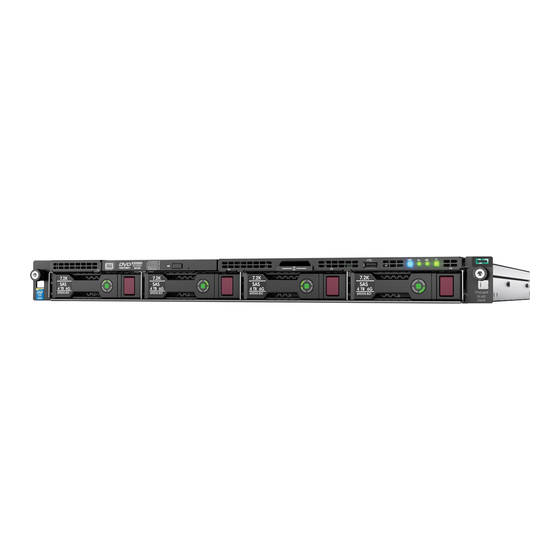
HPE ProLiant DL60 Gen9 Server
Maintenance and Service Guide
Abstract
This guide describes identification and maintenance procedures, diagnostic tools, specifications and requirements for hardware
components and software. This guide is for an experienced service technician. Hewlett Packard Enterprise assumes that you are qualified
in the servicing of computer equipment, trained in recognizing hazards in products, and are familiar with weight and stability precautions.
Part Number: 786244-004
February 2017
Edition: 4
Advertisement
Table of Contents

Related Manuals for Hewlett Packard Enterprise ProLiant DL60 Gen9


Summary of Contents for Hewlett Packard Enterprise ProLiant DL60 Gen9
- Page 1 This guide describes identification and maintenance procedures, diagnostic tools, specifications and requirements for hardware components and software. This guide is for an experienced service technician. Hewlett Packard Enterprise assumes that you are qualified in the servicing of computer equipment, trained in recognizing hazards in products, and are familiar with weight and stability precautions.
- Page 2 © Copyright 2014, 2017 Hewlett Packard Enterprise Development LP The information contained herein is subject to change without notice. The only warranties for Hewlett Packard Enterprise products and services are set forth in the express warranty statements accompanying such products and services. Nothing herein should be construed as constituting an additional warranty.
-
Page 3: Table Of Contents
Contents Customer self repair............................ 6 Parts only warranty service ............................6 Illustrated parts catalog ..........................16 Mechanical components............................16 System components ..............................19 Removal and replacement procedures ....................24 Required tools ................................24 Safety considerations ............................... 24 Preventing electrostatic discharge ........................ 24 Symbols on equipment .......................... - Page 4 System board ................................68 HPE 550-W Power Supply ............................75 Redundant power supply components ........................76 Power input module and RPS backplane characteristics ................76 Hot-plug power input module ........................76 Redundant power supply backplane ......................77 HP Trusted Platform Module ............................ 78 Troubleshooting ............................
- Page 5 Documentation feedback ........................111 Index................................ 112 Contents 5...
-
Page 6: Customer Self Repair
CSR part whether a defective part must be returned to Hewlett Packard Enterprise. In cases where it is required to return the defective part to Hewlett Packard Enterprise, you must ship the defective part back to Hewlett Packard Enterprise within a defined period of time, normally five (5) business days. - Page 7 Votre garantie limitée Hewlett Packard Enterprise peut inclure un service de garantie "pièces seules". Dans ce cas, les pièces de rechange fournies par Hewlett Packard Enterprise ne sont pas facturées. Dans le cadre de ce service, la réparation des pièces CSR par le client est obligatoire. Si vous demandez à...
- Page 8 In caso di necessità si può richiedere l'assistenza telefonica di un addetto del centro di supporto tecnico Hewlett Packard Enterprise. Nel materiale fornito con una parte di ricambio CSR, Hewlett Packard Enterprise specifica se il cliente deve restituire dei component. Qualora...
- Page 9 NOTA: Algunos componentes de Hewlett Packard Enterprise no están diseñados para que puedan ser reparados por el usuario. Para que el usuario haga valer su garantía, Hewlett Packard Enterprise pone como condición que un proveedor de servicios autorizado realice la sustitución de estos componentes.
- Page 10 Para este servicio de garantía exclusivo de componentes, es obligatoria la sustitución de componentes por parte del usuario (CSR). Si solicita a Hewlett Packard Enterprise que realice la sustitución de estos componentes, tendrá que hacerse cargo de los gastos de desplazamiento y de mano de obra de dicho servicio.
- Page 11 OBSERVAÇÃO: Algumas peças da Hewlett Packard Enterprise não são projetadas para o reparo feito pelo cliente. A fim de cumprir a garantia do cliente, a Hewlett Packard Enterprise exige que um técnico autorizado substitua a peça. Essas peças estão identificadas com a marca "No" (Não), no catálogo de peças ilustrado.
- Page 12 Hewlett Packard Enterprise (http://www.hpe.com/support/selfrepair). Serviço de garantia apenas para peças A garantia limitada da Hewlett Packard Enterprise pode incluir um serviço de garantia apenas para peças. Segundo os termos do serviço de garantia apenas para peças, a Hewlett Packard Enterprise fornece as peças de reposição sem cobrar nenhuma taxa.
- Page 13 Customer self repair 13...
- Page 14 Customer self repair 14...
- Page 15 Customer self repair 15...
-
Page 16: Illustrated Parts Catalog
Optional—Parts for which customer self repair is optional. These parts are also designed for customer self repair. If, however, you require that Hewlett Packard Enterprise replace them for you, there may or may not be additional charges, depending on the type of warranty service designated for your product. - Page 17 » dans le Catalogue de pièces illustré. Obbligatorio—Parti per le quali il cliente è tenuto a effettuare autonomamente la riparazione. Se si richiede l'intervento di Hewlett Packard Enterprise per la sostituzione di queste parti, al cliente verranno addebitate le spese di viaggio e manodopera dell'operazione.
- Page 18 Opcional—Peças cujo reparo feito pelo cliente é opcional. Essas peças também são projetadas para o reparo feito pelo cliente. No entanto, se desejar que a Hewlett Packard Enterprise as substitua, pode haver ou não a cobrança de taxa adicional, dependendo do tipo de serviço de garantia destinado ao produto.
-
Page 19: System Components
System components Hewlett Packard Enterprise continually improves and changes product parts. For complete and current supported parts information, see the Hewlett Packard Enterprise PartSurfer website (http://www.hpe.com/info/partssurfer). Item Description Spare part Customer self number repair (on page System boards (includes alcohol pad and thermal compound) —... - Page 20 Item Description Spare part Customer self number repair (on page a) 1.6-GHz Intel Xeon E5-2603 v3, 6C, 85 W** 762441-001 Optional b) 1.8-GHz Intel Xeon E5-2650L v3, 12C, 65 W* ** 762461-001 Optional c) 1.8-GHx Intel Xeon E5-2630L v3, 8C, 55W* ** 762459-001 Optional d) 1.9-GHz Intel Xeon E5-2609 v3, 6C, 85 W* **...
- Page 21 Optional—Parts for which customer self repair is optional. These parts are also designed for customer self repair. If, however, you require that Hewlett Packard Enterprise replace them for you, there may or may not be additional charges, depending on the type of warranty service designated for your product.
- Page 22 Opcional—Peças cujo reparo feito pelo cliente é opcional. Essas peças também são projetadas para o reparo feito pelo cliente. No entanto, se desejar que a Hewlett Packard Enterprise as substitua, pode haver ou não a cobrança de taxa adicional, dependendo do tipo de serviço de garantia destinado ao produto.
- Page 23 Illustrated parts catalog 23...
-
Page 24: Removal And Replacement Procedures
Removal and replacement procedures Required tools You need the following items for some procedures: • T-25 Torx screwdriver (for screws located inside the front panel quick-release levers) • T-10/T-15 Torx screwdriver • Flathead screwdriver (for replacing the system battery) • HPE Insight Diagnostics (on page 84) Safety considerations Before performing service procedures, review all the safety information. -
Page 25: Server Warnings And Cautions
• Get help to lift and stabilize the product during installation or removal, especially when the product is not fastened to the rails. Hewlett Packard Enterprise recommends that a minimum of two people are required for all rack server installations. A third person may be required to help align the server if the server is installed higher than chest level. -
Page 26: Preparation Procedures
Extend the server from the rack (on page 27). If you are performing service procedures in an Hewlett Packard Enterprise, Compaq branded, Telco, or third-party rack cabinet, you can use the locking feature of the rack rails to support the server and gain access to internal components. -
Page 27: Power Down The Server
Before proceeding, verify the server is in standby mode by observing that the system power LED is amber. Extend the server from the rack To extend the server from a Hewlett Packard Enterprise, Compaq-branded, Telco, or third-party rack: Removal and replacement procedures 27... - Page 28 WARNING: To reduce the risk of personal injury or equipment damage, be sure that the rack is adequately stabilized before extending a component from the rack. WARNING: To reduce the risk of personal injury, be careful when pressing the server rail-release latches and sliding the server into the rack.
- Page 29 Slide the server out of the enclosure. iii. After performing the installation or maintenance procedure, slide the server back into the enclosure, and then press the server firmly into the enclosure to secure it in place. Do one of the following: In a server that uses thumbscrew rack ears, tighten the captive thumbscrews.
-
Page 30: Access The Product Rear Panel
Access the product rear panel Opening the cable management arm To access the server rear panel: Release the cable management arm. Open the cable management arm. The cable management arm can be right-mounted or left-mounted. Remove the server from the rack Removal and replacement procedures 30... -
Page 31: Remove The Air Baffle
• Use caution when installing the server in or removing the server from the rack; it is unstable when not fastened to the rails. To remove the server from a Hewlett Packard Enterprise, Compaq-branded, Telco, or a third-party enclosure: Power down the server (on page 27). -
Page 32: Remove The Pci Riser Cage
Remove the PCI riser cage WARNING: To reduce the risk of personal injury from hot surfaces, allow the drives and the internal system components to cool before touching them. CAUTION: To prevent damage to the server or expansion boards, power down the server, and disconnect all power cords before removing or installing the PCI riser cage. - Page 33 Secondary PCI riser cage PCI blank Removal and replacement procedures 33...
-
Page 34: Non-Hot-Plug Drive Carrier
Remove any expansion boards installed in the primary riser cage. Remove the primary PCI riser cage. Non-hot-plug drive carrier CAUTION: To prevent improper cooling and thermal damage, do not operate the server unless all bays are populated with either a component or a blank. To remove the component: Power down the server (on page 27). -
Page 35: Non-Hot-Plug Drive
Remove the drive carrier. To replace the component, slide the component into the bay until it clicks. Non-hot-plug drive CAUTION: To prevent improper cooling and thermal damage, do not operate the server unless all bays are populated with either a component or a blank. To remove the component: Back up all server data on the drive. -
Page 36: Hot-Plug Drive Blanks
Remove the drive from the carrier. To replace the component, reverse the removal procedure. Hot-plug drive blanks CAUTION: To prevent improper cooling and thermal damage, do not operate the server unless all bays are populated with either a component or a blank. To remove the component: If installed, remove the security bezel ("Remove the security bezel... -
Page 37: Access Panel
Remove the hot-plug drive. To replace the component, reverse the removal procedure. Access panel To remove the component: WARNING: To reduce the risk of personal injury from hot surfaces, allow the drives and the internal system components to cool before touching them. CAUTION: Do not operate the server for long periods with the access panel open or removed. -
Page 38: Four-Bay Lff Non-Hot-Plug Drive Backplane
If the access panel latch is locked, use a T-15 Torx screwdriver to unlock the latch. To replace the component, reverse the removal procedure. Four-bay LFF non-hot-plug drive backplane To remove the component: Power down the server (on page 27). Remove all power: Disconnect each power cord from the power source. -
Page 39: Four-Bay Lff Hot-Plug Drive Backplane
Remove the non-hot-plug drive backplane. To replace the component, reverse the removal procedure. Four-bay LFF hot-plug drive backplane To remove the component: Power down the server (on page 27). Remove all power: Disconnect each power cord from the power source. Disconnect each power cord from the server. -
Page 40: Smart Storage Battery
Smart Storage Battery For more information about product features, specifications, options, configurations, and compatibility, see the product QuickSpecs on the Hewlett Packard Enterprise website (http://www.hpe.com/info/qs). CAUTION: In systems that use external data storage, be sure that the server is the first unit to be powered down and the last to be powered back up. - Page 41 CAUTION: To prevent damage to electrical components, take the appropriate anti-static precautions before beginning any installation, removal, or replacement procedure. Improper grounding can cause electrostatic discharge. To remove the component: Power down the server (on page 27). Remove all power: Disconnect each power cord from the power source.
-
Page 42: M.2 Ssd Enablement Kit
Remove the cache module. To replace the component, reverse the removal procedure. M.2 SSD enablement kit M.2 SSD enablement board WARNING: To reduce the risk of personal injury from hot surfaces, allow the drives, power input modules, and the internal system components to cool before touching them. CAUTION: To prevent damage to electrical components, take the appropriate anti-static precautions before beginning any system installation. -
Page 43: M.2 Ssd Module
Slot 2 Slot 3 To replace the component, reverse the removal procedure. M.2 SSD module WARNING: To reduce the risk of personal injury from hot surfaces, allow the drives, power input modules, and the internal system components to cool before touching them. CAUTION: To prevent damage to electrical components, take the appropriate anti-static precautions before beginning any system installation. -
Page 44: Optical Drive Blank
Disconnect each power cord from the power source. Disconnect each power cord from the server. Do one of the following: Extend the server from the rack (on page 27). Remove the server from the rack (on page 30). Remove the access panel ("Access panel"... -
Page 45: Optical Drive
Remove the optical drive blank To replace the component, reverse the removal procedure. Optical drive WARNING: To reduce the risk of personal injury from hot surfaces, allow the drives, power input modules, and the internal system components to cool before touching them. CAUTION: To prevent damage to electrical components, take the appropriate anti-static precautions before beginning any system installation. - Page 46 Disconnect the optical drive cable from the drive. Remove the optical drive: To replace the component, reverse the removal procedure. Removal and replacement procedures 46...
-
Page 47: Fan And Fan Blank
Fan and fan blank Fan population guidelines Configuration Fan bay Fan bay Fan bay Fan bay Fan bay Fan bay Blank Blank Blank One processor, non-redundant Blank One processor, redundant Blank Blank Two processors, non-redundant Two processors, redundant • In the redundant fan mode: If one fan rotor fails, the system continues to operate without redundancy. -
Page 48: Hot-Swap Fan
Remove all power: Disconnect each power cord from the power source. Disconnect each power cord from the server. Disconnect all peripheral cables and power cords from the rear panel. Do one of the following: Extend the server from the rack (on page 27). Remove the server from the rack (on page 30). -
Page 49: Dimms
Remove the access panel ("Access panel" on page 37). Remove the air baffle (on page 31). Disconnect the fan cable from the system board and remove the fan. CAUTION: The fan does not have a fan guard. Special attention is needed when removing or installing the fan to prevent finger injury. -
Page 50: Heatsink
Remove the server from the rack (on page 30). Remove the access panel ("Access panel" on page 37). Remove any expansion board installed in slot 1 and 2. ("Expansion board" on page 58) Open the DIMM slot latches. Remove the DIMM. To replace the component, reverse the removal procedure. - Page 51 Remove the heatsink from the processor backplate. To replace the component: Clean the old thermal grease from the processor with the alcohol swab. Allow the alcohol to evaporate before continuing. Remove the thermal interface protective cover from the heatsink. Install the heatsink: Position the heatsink on the processor backplate.
-
Page 52: Processor Blank
Finish the installation by completely tightening the screws in the same sequence. Install the air baffle. Install the access panel. Do one of the following: Slide the server into the rack. Install the server into the rack. Connect each power cord to the server. Connect each power cord to the power source. -
Page 53: Processor
IMPORTANT: Processor socket 1 must be populated at all times or the server does not function. In a multiprocessor configuration, to optimize system performance, Hewlett Packard Enterprise recommends balancing the total capacity of the DIMMs across the processors. To remove the component: Power down the server (on page 27). - Page 54 Remove all power: Disconnect each power cord from the power source. Disconnect each power cord from the server. Do one of the following: Extend the server from the rack (on page 27). Remove the server from the rack (on page 30). Remove the access panel ("Access panel"...
- Page 55 Open each of the processor locking levers in the order indicated, and then open the processor retaining bracket. CAUTION: THE PINS ON THE SYSTEM BOARD ARE VERY FRAGILE AND EASILY DAMAGED. To avoid damage to the system board, do not touch the processor or the processor socket contacts.
- Page 56 To replace the component: Install the processor. Verify that the processor is fully seated in the processor retaining bracket by visually inspecting the processor installation guides on either side of the processor. THE PINS ON THE SYSTEM BOARD ARE VERY FRAGILE AND EASILY DAMAGED. CAUTION: THE PINS ON THE SYSTEM BOARD ARE VERY FRAGILE AND EASILY DAMAGED.
- Page 57 Press and hold the processor retaining bracket in place, and then close each processor locking lever. Press only in the area indicated on the processor retaining bracket. Clean the old thermal grease from the heatsink with the alcohol swab. Allow the alcohol to evaporate before continuing.
-
Page 58: Expansion Board
Finish the installation by completely tightening the screws in the same sequence. Install the air baffle. Install the access panel. Do one of the following: Slide the server into the rack. Install the server into the rack. Connect each power cord to the server. Connect each power cord to the power source. - Page 59 Remove the server from the rack (on page 30). Remove the access panel ("Access panel" on page 37). Disconnect all cables connected to existing expansion boards. Remove the PCI riser cage (on page 32). Remove the expansion board. Slot 1 Slot 2 Slot 3 Removal and replacement procedures 59...
-
Page 60: Pci Blank
To replace the component, reverse the removal procedure. PCI blank WARNING: To reduce the risk of personal injury from hot surfaces, allow the drives, power input modules, and the internal system components to cool before touching them. CAUTION: To prevent damage to electrical components, take the appropriate anti-static precautions before beginning any system installation. -
Page 61: Full-Height/Half-Length Pcie Riser Board And Cage
To remove the component: Power down the server (on page 27). Remove all power: Disconnect each power cord from the power source. Disconnect each power cord from the server. Do one of the following: Extend the server from the rack (on page 27). Remove the server from the rack (on page 30). - Page 62 WARNING: To reduce the risk of personal injury from hot surfaces, allow the drives, power input modules, and the internal system components to cool before touching them. CAUTION: To prevent damage to electrical components, take the appropriate anti-static precautions before beginning any system installation. Improper grounding can cause electrostatic discharge.
-
Page 63: Flexiblelom Riser Assembly
To replace the component, reverse the removal procedure. FlexibleLOM riser assembly WARNING: To reduce the risk of personal injury from hot surfaces, allow the drives, power input modules, and the internal system components to cool before touching them. CAUTION: To prevent damage to electrical components, take the appropriate anti-static precautions before beginning any system installation. -
Page 64: System Battery
Remove the FlexibleLOM adapter from the riser cage. To replace the component, reverse the removal procedure. System battery If the server no longer automatically displays the correct date and time, then replace the battery that provides power to the real-time clock. Under normal use, battery life is 5 to 10 years. WARNING: The computer contains an internal lithium manganese dioxide, a vanadium pentoxide, or an alkaline battery pack. -
Page 65: Front I/O Module
IMPORTANT: Replacing the system board battery resets the system ROM to its default configuration. After replacing the battery, use BIOS/Platform Configuration (RBSU) in the UEFI System Utilities ("HPE UEFI System Utilities" on page 83) to reconfigure the system. To replace the component: Insert the battery with the "+"... -
Page 66: Thumbscrew Rack Ear Assembly
Remove all power: Disconnect each power cord from the power source. Disconnect each power cord from the server. Do one of the following: Extend the server from the rack (on page 27). Remove the server from the rack (on page 30). Remove the access panel ("Access panel"... -
Page 67: Quick-Release Latch Rack Ear Assembly
Remove the thumbscrew rack ear assembly. To replace the component, reverse the removal procedure. Quick-release latch rack ear assembly WARNING: To reduce the risk of personal injury from hot surfaces, allow the drives and the internal system components to cool before touching them. CAUTION: To prevent damage to electrical components, take the appropriate anti-static precautions before beginning any installation, removal, or replacement procedure. -
Page 68: System Board
Remove the quick-release latch rack ear assembly. To replace the component, reverse the removal procedure. System board WARNING: To reduce the risk of personal injury from hot surfaces, allow the drives and the internal system components to cool before touching them. CAUTION: To prevent damage to electrical components, take the appropriate anti-static precautions before beginning any installation, removal, or replacement procedure. - Page 69 If installed, remove the processor blank. Remove the heatsink: Loosen one pair of diagonally opposite screws halfway, and then loosen the other pair of screws. Completely loosen all screws in the same sequence. Remove the heatsink from the processor backplate. Open each of the processor locking levers in the order indicated, and then open the processor retaining bracket.
- Page 70 Remove the processor from the processor retaining bracket. CAUTION: When returning a damaged system board to Hewlett Packard Enterprise, always install all processor socket covers to prevent damage to the processor sockets and system board. Remove the system board: Remove the system board screws.
- Page 71 To replace the system board assembly: Install the system board assembly. Open each of the processor locking levers in the order indicated, and then open the processor retaining bracket. Removal and replacement procedures 71...
- Page 72 Remove the clear processor socket cover. Retain the processor socket cover for future use. Install the processor. Verify that the processor is fully seated in the processor retaining bracket by visually inspecting the processor installation guides on either side of the processor. THE PINS ON THE SYSTEM BOARD ARE VERY FRAGILE AND EASILY DAMAGED.
- Page 73 Press and hold the processor retaining bracket in place, and then close each processor locking lever. Press only in the area indicated on the processor retaining bracket. Install the processor socket cover on the failed system board. Clean the old thermal grease from the heatsink and the top of the processor with the alcohol swab. Allow the alcohol to evaporate before continuing.
- Page 74 Finish the installation by completely tightening the screws in the same sequence. Install the fans. Install all components removed from the failed system board. Connect all cables disconnected from the failed system board. Install the PCI riser cages. Install the air baffle ("Remove the air baffle"...
-
Page 75: Hpe 550-W Power Supply
Warning: The Product ID should ONLY be modified by qualified service personnel. This value should always match the Product ID located on the chassis. Enter the product ID and press the Enter key. Press the F10 key to confirm exiting System Utilities. The server automatically reboots. HPE 550-W Power Supply WARNING: To reduce the risk of personal injury from hot surfaces, allow the drives and the internal system components to cool before touching them. -
Page 76: Redundant Power Supply Components
Remove the non-hot-plug power supply. To replace the component, reverse the removal procedure. Redundant power supply components Power input module and RPS backplane characteristics • HPE 800 W/900 W Gold AC Power Input Module (744689-B21) This module is compatible with the AC RPS backplane (745813-B21). The module wattage rating changes depending on whether one or two power input modules are installed in the server: —... -
Page 77: Redundant Power Supply Backplane
Remove the power input module. To replace the component, reverse the removal procedure. Redundant power supply backplane WARNING: To reduce the risk of personal injury from hot surfaces, allow the drives and the internal system components to cool before touching them. CAUTION: To prevent damage to electrical components, take the appropriate anti-static precautions before beginning any installation, removal, or replacement procedure. -
Page 78: Hp Trusted Platform Module
Remove the server from the rack (on page 30). Place the server on a sturdy, level surface. Remove the access panel ("Access panel" on page 37). If installed, remove the primary PCI riser cage ("Remove the PCI riser cage" on page 32). Disconnect the RPS backplane cables. - Page 79 If you suspect a TPM board failure, leave the TPM installed and remove the system board. Contact a Hewlett Packard Enterprise authorized service provider for a replacement system board and TPM board. Removal and replacement procedures 79...
-
Page 80: Troubleshooting
Troubleshooting Troubleshooting resources The HPE ProLiant Gen9 Troubleshooting Guide, Volume I: Troubleshooting provides procedures for resolving common problems and comprehensive courses of action for fault isolation and identification, issue resolution, and software maintenance on ProLiant servers and server blades. To view the guide, select a language: •... -
Page 81: Diagnostic Tools
Product QuickSpecs For more information about product features, specifications, options, configurations, and compatibility, see the product QuickSpecs on the Hewlett Packard Enterprise website (http://www.hpe.com/info/qs). HPE iLO The iLO 4 subsystem is a standard component of ProLiant servers that simplifies initial server setup, server health monitoring, power and thermal optimization, and remote server administration. -
Page 82: Hpe Proliant Pre-Boot Health Summary
The data that is collected is managed according to the Hewlett Packard Enterprise Data Privacy policy. For more information see the Hewlett Packard Enterprise website (http://www.hpe.com/info/privacy). -
Page 83: Integrated Management Log
Provisioning For more information on the UEFI System Utilities, see the HPE UEFI System Utilities User Guide for HPE ProLiant Gen9 Servers on the Hewlett Packard Enterprise website (http://www.hpe.com/info/uefi/docs). Scan the QR code located at the bottom of the screen to access mobile-ready online help for the UEFI System Utilities and UEFI Shell. -
Page 84: Embedded Diagnostics Option
Available in Microsoft Windows and Linux versions, the utility helps to ensure proper system operation. For more information or to download the utility, see the Hewlett Packard Enterprise website (http://www.hpe.com/info/InsightDiagnostics). The Insight Diagnostics Online Edition is also available in the SPP. -
Page 85: Hpe Insight Diagnostics Survey Functionality
USB support Hewlett Packard Enterprise servers support both USB 2.0 ports and USB 3.0 ports. Both types of ports support installing all types of USB devices (USB 1.0, USB 2.0, and USB 3.0), but may run at lower speeds in specific situations: •... -
Page 86: External Usb Functionality
(http://www.hpe.com/info/uefi/docs). External USB functionality Hewlett Packard Enterprise provides external USB support to enable local connection of USB devices for server administration, configuration, and diagnostic procedures. For additional security, external USB functionality can be disabled through USB options in UEFI System Utilities. -
Page 87: Component Identification
Component identification Front panel components Item Description Optical drive (optional) Serial label pull tab The serial number/iLO information pull tab is double-sided. The top side shows the server serial number and the customer asset tag label. The reverse side shows the default iLO account information and QR code label. -
Page 88: Front Panel Leds And Buttons
Front panel LEDs and buttons Item Description Status UID button/LED Solid blue = Activated Flashing blue: • 1 flash per second = Remote management or firmware upgrade in progress • 4 flashes per second = iLO manual reboot sequence initiated •... -
Page 89: Front Panel Led Power Fault Codes
Front panel LED power fault codes The following table provides a list of power fault codes, and the subsystems that are affected. Not all power faults are used by all servers. Subsystem Front panel LED behavior 1 flash System board 2 flashes Processor 3 flashes... -
Page 90: Rear Panel Leds
Rear panel LEDs Item Description Status UID LED Solid blue = Activated Flashing blue: • 1 flash per second = Remote management or firmware upgrade in progress • 4 flashes per second = iLO manual reboot sequence initiated • 8 flashes per second = iLO manual reboot sequence in progress Off = Deactivated NIC link LED... -
Page 91: System Board Components
System board components Item Description Primary PCIe riser board connector* TPM connector System battery SATA connector Storage backup power connector for PCIe slots 1-2 Reserved Secondary PCIe riser board connector* MicroSD slot Storage backup power connector for PCIe slot 3 System maintenance switch NMI header Reserved... -
Page 92: Dimm Slot Locations
DIMM slot locations DIMM slots are numbered sequentially (1 through 4) for each processor. The supported AMP modes use the letter assignments for population guidelines. The arrow points to the front of the server. System maintenance switch Position Default Function Off = iLO 4 security is enabled. -
Page 93: Nmi Functionality
To force the system to invoke the NMI handler and generate a crash dump log, do one of the following: • Use the iLO Virtual NMI feature. • Short the NMI header ("System board components" on page 91). For more information, see the Hewlett Packard Enterprise website (http://www.hpe.com/support/NMI-CrashDump). Drive numbering Component identification 93... -
Page 94: Hot-Plug Drive Led Definitions
Hot-plug drive LED definitions Item Status Definition Locate Solid blue The drive is being identified by a host application. Flashing blue The drive carrier firmware is being updated or requires an update. Activity ring Rotating green Drive activity No drive activity Do not remove Solid white Do not remove the drive. -
Page 95: Fan Locations
Fan locations Component identification 95... -
Page 96: Cabling
For information on cabling peripheral components, refer to the white paper on high-density deployment at the Hewlett Packard Enterprise website (http://www.hpe.com/info/servers). CAUTION: When routing cables, always be sure that the cables are not in a position where they can be pinched or crimped. -
Page 97: Four-Bay Lff Hot-Plug Drive Cabling
• Four-bay LFF non-hot-plug drive backplane connected to the H240 Host Bus Adapter Item Description Drive power cable Mini-SAS cable Four-bay LFF hot-plug drive cabling • Four-bay LFF drive backplane connected to the system board Item Description Drive power cable Mini-SAS cable Cabling 97... -
Page 98: Fbwc Cabling
• Four-bay LFF drive backplane connected to a P440 controller in the low-profile expansion slot 1 Item Description Drive power cable Mini-SAS cable • Four-bay LFF drive backplane connected to a H240 adapter in the low-profile expansion slot 1 Item Description Drive power cable Mini-SAS cable... - Page 99 Depending on the controller option installed, the actual storage controller connectors might look different from what is shown in this section. • FBWC module slot 1 cabling • FBWC module slot 2 cabling Cabling 99...
-
Page 100: M.2 Ssd Cabling
• FBWC module slot 3 cabling M.2 SSD cabling • Slot 2 cable routing (2 ports supported when slot 1 is unoccupied) Cabling 100... - Page 101 • Slot 2 cable routing (1 port supported when slot 1 is occupied) • Slot 3 cable routing (2 ports supported when slot 1 is unoccupied) Cabling 101...
- Page 102 • Slot 3 cable routing (1 port supported when slot 1 is occupied) • Slot 2 cable routing with FlexibleLOM riser (2 ports supported when slot 1 is unoccupied) Cabling 102...
-
Page 103: Smart Storage Battery Cabling
• Slot 2 cable routing with FlexibleLOM riser (1 port supported when slot 1 is occupied) Smart Storage battery cabling Cabling 103... -
Page 104: Power Supply Cabling
Power supply cabling • HPE 550 W non-hot-plug power supply cabling Item Description 16-pin power supply sideband signal cable 24-pin power supply cable • HPE Redundant Power Supply cabling Item Description 16-pin power supply sideband signal cable 24-pin power supply cable Reserved Cabling 104... -
Page 105: Optical Drive Cabling
Optical drive cabling Item Description Optical drive cable Drive power cable Front I/O cabling Item Description Front I/O cable USB 2.0 connector cable Ambient temperature sensor cable Cabling 105... -
Page 106: Specifications
40°C to 45°C (104°F to 113°F) at sea level with an altitude derating of 1.0°C per every 125 m (1.8°F per every 410 ft) above 900 m (2953 ft) to a maximum of 3048 m (10,000 ft). The approved hardware configurations for this system are listed on the Hewlett Packard Enterprise website (http://www.hpe.com/servers/ASHRAE). -
Page 107: Hot-Plug Power Supply Calculations
CAUTION: Check the system and power supply input ratings before powering up the server. Hot-plug power supply calculations For hot-plug power supply specifications and calculators to determine electrical and heat loading for the server, see the Hewlett Packard Enterprise Power Advisor website (http://www.hpe.com/info/poweradvisor/online). Specifications 107... -
Page 108: Acronyms And Abbreviations
Acronyms and abbreviations ABEND abnormal end alternating current Advanced Memory Protection application program interface ASHRAE American Society of Heating, Refrigerating and Air-Conditioning Engineers Customer Self Repair FBWC flash-backed write cache graphics processing unit host bus adapter HPE SIM HPE Systems Insight Manager hertz Integrated Lights-Out Integrated Management Log... - Page 109 large form factor nonmaskable interrupt NVRAM nonvolatile memory PCIe Peripheral Component Interconnect Express POST Power-On Self Test power supply unit RBSU ROM-Based Setup Utility redundant power supply serial attached SCSI SATA serial ATA Secure Digital Systems Insight Manager Service Pack for ProLiant Trusted Platform Module UEFI Unified Extensible Firmware Interface...
- Page 110 unit identification universal serial bus Acronyms and abbreviations 110...
- Page 111 Documentation feedback Hewlett Packard Enterprise is committed to providing documentation that meets your needs. To help us improve the documentation, send any errors, suggestions, or comments to Documentation Feedback (mailto:docsfeedback@hpe.com). When submitting your feedback, include the document title, part number, edition, and publication date located on the front cover of the document. For online help content, include the product name, product version, help edition, and publication date located on the legal notices page.
- Page 112 23, 24 health driver 85 components, front panel 86 heatsink 49 components, system board 90 Hewlett Packard Enterprise Technical Support 6 crash dump analysis 92 hot-plug drive backplane 38 customer self repair (CSR) 6 hot-plug drive blank 35 hot-plug drive, removing 35...
- Page 113 rear panel components 88 rear panel LEDs 89 LEDs, drive 93 rear panel, accessing 29 LEDs, front panel 93 redundant power supply 75, 76, 105 LEDs, power fault 88 re-entering the server serial number 83 legacy USB support 84 remote support and analysis tools 84 removal and replacement procedures 23 remove server from rack 29 required tools 23...
Need help?
Do you have a question about the ProLiant DL60 Gen9 and is the answer not in the manual?
Questions and answers