Table of Contents
Advertisement
Quick Links
HPE ProLiant XL170r Gen10 Server
Maintenance and Service Guide
Abstract
This guide describes identification and maintenance procedures, diagnostic tools, specifications, and
requirements for hardware components and software. This guide is for an experienced service technician.
Hewlett Packard Enterprise assumes you are qualified in the servicing of computer equipment, trained in
recognizing hazards in products, and are familiar with weight and stability precautions.
Part Number: 879103-007
Published: December 2019
Edition: 7
Advertisement
Table of Contents

Subscribe to Our Youtube Channel
Related Manuals for Hewlett Packard Enterprise HPE ProLiant XL170r Gen10


Summary of Contents for Hewlett Packard Enterprise HPE ProLiant XL170r Gen10
- Page 1 This guide is for an experienced service technician. Hewlett Packard Enterprise assumes you are qualified in the servicing of computer equipment, trained in recognizing hazards in products, and are familiar with weight and stability precautions.
- Page 2 Copyright 2017-2019 Hewlett Packard Enterprise Development LP Notices The information contained herein is subject to change without notice. The only warranties for Hewlett Packard Enterprise products and services are set forth in the express warranty statements accompanying such products and services.
-
Page 3: Table Of Contents
Contents Illustrated parts catalog....................7 Mechanical components......................................7 Air baffle spare part......................................7 System components........................................7 Bayonet board spare parts..................................8 Processor spare parts....................................8 Heatsink spare parts....................................10 System battery spare part..................................10 DIMM spare parts......................................11 HPE Persistent Memory module spare parts..........................11 System board assembly spare parts.............................. - Page 4 Install the secondary riser cage................................36 Install the bayonet board..................................37 Install the air baffle.....................................39 Install the server into the chassis..............................40 Power up the server....................................40 Selecting an advanced fan cooling method..........................41 Disconnecting and replacing the SUV cable..............................41 Removing and replacing the bayonet boards..............................41 Removing and replacing an expansion board..............................42 Removing and replacing an HPE InfiniBand HDR/Ethernet 200 GB 1-port 940QSFP56 x16 adapter and auxiliary card...........................................
- Page 5 97 Thermal limitations for components in systems with the Enhanced Processor Performance feature disabled......................................110 Websites......................... 124 Support and other resources..................125 Accessing Hewlett Packard Enterprise Support............................. 125 Accessing updates........................................125 Customer self repair.........................................126 Remote support..........................................126 Warranty information......................................126 Regulatory information......................................
- Page 6 Acronyms and abbreviations..................128...
-
Page 7: Illustrated Parts Catalog
Illustrated parts catalog Mechanical components Hewlett Packard Enterprise continually improves and changes product parts. For complete and current supported parts information, see the Hewlett Packard Enterprise PartSurfer website. Item Description Air baffle spare part Air baffle spare part Customer self repair: Mandatory... -
Page 8: Bayonet Board Spare Parts
Item Description Small bayonet board spare part Large bayonet board spare part First-generation Intel Xeon Scalable Processor spare parts Second-generation Intel Xeon Scalable Processor spare parts Heatsink spare parts System battery spare part DIMM spare parts System board assembly spare parts System cable spare parts* *Not shown Bayonet board spare parts... - Page 9 Description Spare part number 1.90 GHz Intel Xeon Gold 5119T, 14C, 85 W 882170-001 2.00 GHz Intel Xeon Gold 6138, 20C, 125 W 874735-001 2.00 GHz Intel Xeon Gold 6138F, 20C, 135 W 878095-001 2.10 GHz Intel Xeon Gold 6130, 16C, 125 W 874736-001 2.10 GHz Intel Xeon Gold 6130F, 16C, 135 W 878096-001...
-
Page 10: Heatsink Spare Parts
Description Spare part number Intel Xeon Silver series processors — 2.10 GHz Intel Xeon Silver 4208, 8C, 85 W P11605-001 2.10 GHz Intel Xeon Silver 4216, 16C, 100 W P11609-001 2.20 GHz Intel Xeon Silver 4210, 10C, 85 W P11606-001 2.20 GHz Intel Xeon Silver 4214, 12C, 85 W P11607-001 2.50 GHz Intel Xeon Silver 4215, 8C, 85 W... -
Page 11: Dimm Spare Parts
DIMM spare parts Customer self repair: Mandatory Description Spare part number PC4-2666V DIMM spares — 8 GB, single-rank x8 PC4-2666V-R 850879-001 16 GB, single-rank x4 PC4-2666V-R 868846-001 16 GB, dual-rank x8 PC4-2666V-R 850880-001 32 GB, dual-rank x4 PC4-2666V-R 850881-001 8 GB, dual-rank x8 PC4-2666V-R 878490-001 64 GB, dual-rank x4 PC4-2666V-L 850882-001... -
Page 12: Server Options
1U server NVMe cable • 2U server NVMe cable Server options Hewlett Packard Enterprise continually improves and changes product parts. For complete and current supported parts information, see the Hewlett Packard Enterprise PartSurfer website. Item Description M.2 SSD riser board spare part... -
Page 13: M.2 Ssd Riser Board Spare Part
Item Description Smart Array controller spare parts Media Module adapter spare parts HPE Trusted Platform Module 2.0 spare part* SUV cable spare part* OPA adapter cable spare kit* Smart Array controller cable spare part* *Not shown M.2 SSD riser board spare part Customer self repair: Optional Description Spare part number... -
Page 14: Ethernet Adapter Spare Part
Description Spare part number HPE IB FDR/EN 40Gb 2P 544+QSFP Adapter 764736-001 HPE IB FDR/EN 40Gb 2P 544+FLR-QSFP Adapter 779132-001 HPE IB EDR 100Gb 1P 841QSFP28 Adapter 878578-001 HPE IB EDR/EN 100Gb 2P 841QSFP28 Adapter 878579-001 HPE IB FDR/EN 40/50Gb 547FLR 2QSFP Adapter 879667-001 HPE IB EDR/EN 100Gb 1P 840QSFP28 Adapter 828107-001... -
Page 15: Suv Cable Spare Part
Description Spare part number HPE Trusted Platform Module Gen 10, TAA 872159-001 SUV cable spare part Customer self repair: Mandatory Description Spare part number 36-pin SUV cable 416003-001 For more information on the removal and replacement procedures, see Disconnecting and replacing the SUV cable. OPA adapter cable spare kit Customer self repair: Optional Description... -
Page 16: Customer Self Repair
Enterprise (or Hewlett Packard Enterprise service providers or service partners) identifies that the repair can be accomplished by the use of a CSR part, Hewlett Packard Enterprise will ship that part directly to you for replacement. There are two categories of CSR parts: •... - Page 17 (5) jours ouvrés. La pièce et sa documentation doivent être retournées dans l'emballage fourni. Si vous ne retournez pas la pièce défectueuse, Hewlett Packard Enterprise se réserve le droit de vous facturer les coûts de remplacement. Dans le cas d'une pièce CSR, Hewlett Packard Enterprise supporte l'ensemble des frais d'expédition et de retour, et détermine la société...
- Page 18 Servizio di garanzia per i soli componenti La garanzia limitata Hewlett Packard Enterprise può includere un servizio di garanzia per i soli componenti. Nei termini di garanzia del servizio per i soli componenti, Hewlett Packard Enterprise fornirà gratuitamente le parti di ricambio.
- Page 19 Hewlett Packard Enterprise podrá cobrarle por el de sustitución. En el caso de todas sustituciones que lleve a cabo el cliente, Hewlett Packard Enterprise se hará cargo de todos los gastos de envío y devolución de componentes y escogerá la empresa de transporte que se utilice para dicho servicio.
- Page 20 Hewlett Packard Enterprise (ou fornecedores/parceiros da Hewlett Packard Enterprise) concluir que o reparo pode ser efetuado pelo uso de uma peça CSR, a Hewlett Packard Enterprise enviará a peça diretamente ao cliente. Há duas categorias de peças CSR: •...
- Page 21 A Hewlett Packard Enterprise especifica nos materiais fornecidos com a peça CSR de reposição se a peça com defeito deve ser devolvida à Hewlett Packard Enterprise. Nos casos em que isso for necessário, é...
- Page 22 Customer self repair...
- Page 23 Customer self repair...
- Page 24 Customer self repair...
-
Page 25: Removal And Replacement Procedures
Get help to lift and stabilize the product during installation or removal, especially when the product is not fastened to the rails. Hewlett Packard Enterprise recommends that a minimum of two people are required for all rack server installations. If the server is installed higher than chest level, a third person may be required to help align the server. -
Page 26: Rack Warnings
WARNING: To reduce the risk of personal injury, electric shock, or damage to the equipment, remove the power cord to remove power from the server. The front panel Power On/Standby button does not completely shut off system power. Portions of the power supply and some internal circuitry remain active until AC/DC power is removed. -
Page 27: Preparation Procedures
WARNING: To reduce the risk of personal injury or damage to the equipment, adequately stabilize the rack before extending a component outside the rack. Extend only one component at a time. A rack may become unstable if more than one component is extended. WARNING: When installing a server in a telco rack, be sure that the rack frame is adequately secured at the top and bottom to the building structure. -
Page 28: Remove The Server From The Chassis
Remove the server from the chassis CAUTION: To prevent improper cooling and thermal damage, do not operate the chassis unless all bays are populated with a component or a blank. CAUTION: To avoid damage to the server or server blank: •... -
Page 29: Remove The Bayonet Board
3. Remove the server from the chassis. 4. Remove the air baffle. Remove the bayonet board Prerequisites Before you perform this procedure, make sure that you have a T-10 Torx screwdriver available. Procedure 1. Power down the server. 2. Disconnect all peripheral cables from the server. 3. -
Page 30: Remove The Secondary Riser Blank
c. Disconnect the bayonet board cables, and then remove the bayonet board. Remove the secondary riser blank CAUTION: To prevent improper cooling and thermal damage, do not operate the server unless either riser blank or riser cage is installed. Prerequisites Before you perform this procedure, make sure that you have a T-10 Torx screwdriver available. -
Page 31: Remove The Secondary Riser Cage
3. Remove the server from the chassis. 4. Remove the secondary riser blank. Remove the secondary riser cage CAUTION: To prevent improper cooling and thermal damage, do not operate the server unless either riser blank or riser cage is installed. Prerequisites Before you perform this procedure, make sure that you have a T-10 Torx screwdriver available. -
Page 32: Remove The Primary Riser Blank
Remove the primary riser blank CAUTION: To prevent improper cooling and thermal damage, do not operate the server unless either riser blank or riser cage is installed. Prerequisites Before you perform this procedure, make sure that you have a T-10 Torx screwdriver available. Procedure 1. -
Page 33: Remove The Primary Riser Cage
Remove the primary riser cage CAUTION: To prevent improper cooling and thermal damage, do not operate the server unless either riser blank or riser cage is installed. Prerequisites Before you perform this procedure, make sure that you have a T-10 Torx screwdriver available. Procedure 1. -
Page 34: Install The Primary Riser Blank
Install the primary riser blank Prerequisites Before you perform this procedure, make sure that you have a T-10 Torx screwdriver available. Procedure 1. Install the primary riser blank. 2. Do one of the following: • Install the secondary riser blank. •... -
Page 35: Install The Primary Riser Cage
4. Install the server into the chassis. 5. Connect all peripheral cables to the server. 6. Power up the server. Install the primary riser cage Prerequisites Before you perform this procedure, make sure that you have a T-10 Torx screwdriver available. Procedure 1. -
Page 36: Install The Secondary Riser Cage
Procedure 1. Install the secondary riser blank. 2. Install the server into the chassis. 3. Connect all peripheral cables to the server. 4. Power up the server. Install the secondary riser cage Prerequisites Before you perform this procedure, make sure that you have a T-10 Torx screwdriver available. Procedure 1. -
Page 37: Install The Bayonet Board
2. Install the bayonet board. 3. Install the air baffle. 4. Install the server into the chassis. 5. Connect all peripheral cables to the server. 6. Power up the server. Install the bayonet board Prerequisites Before you perform this procedure, make sure that you have a T-10 Torx screwdriver available. Procedure 1. - Page 38 c. Install the bayonet board cover, and then install the screws to secure it to the server tray. d. Install the screws to secure the cover to the bayonet board. Removal and replacement procedures...
-
Page 39: Install The Air Baffle
2. Install the air baffle. 3. Install the server into the chassis. 4. Connect all peripheral cables to the server. 5. Power up the server. Install the air baffle Procedure 1. Install the air baffle. 2. Install the server into the chassis. 3. -
Page 40: Install The Server Into The Chassis
Install the server into the chassis CAUTION: To avoid damage to the server or server blank: • Always support the bottom of the server or server blank when removing it from the chassis. • Do not use the release lever to carry the server or server blank. Procedure 1. -
Page 41: Selecting An Advanced Fan Cooling Method
Selecting an advanced fan cooling method Procedure 1. During the server startup sequence, press the F9 key to access System Utilities. 2. From the System Utilities screen, select System Configuration > BIOS/Platform Configuration (RBSU) > Advanced Options > Fan and Thermal Options > Thermal Configuration. 3. -
Page 42: Removing And Replacing An Expansion Board
Procedure 1. Power down the server. 2. Disconnect all peripheral cables from the server. 3. Remove the server from the chassis. 4. Remove the air baffle. 5. Remove the bayonet board. 6. Separate the small bayonet boards from the large bayonet board. To replace the component, reverse the removal procedure. - Page 43 Remove the secondary riser cage • Remove the primary riser cage • 6. If the expansion board has internal cabling, disconnect these internal cables from the expansion board. 7. Remove an expansion board. • Primary riser cage • Secondary riser cage 8.
-
Page 44: Removing And Replacing An Hpe Infiniband Hdr/Ethernet 200 Gb 1-Port 940Qsfp56 X16 Adapter And Auxiliary Card
• Secondary riser cage To replace the component, reverse the removal procedure. Removing and replacing an HPE InfiniBand HDR/Ethernet 200 GB 1- port 940QSFP56 x16 adapter and auxiliary card An HPE InfiniBand HDR/Ethernet 200 GB 1-port 940QSFP56 x16 adapter is installed in slot 1 and auxiliary card is installed in slot 2. - Page 45 a. Disconnect each power cord from the power source. b. Disconnect each power cord from the server. Disconnect all peripheral cables from the server. Remove the server from the chassis. Remove the air baffle. Remove the bayonet board. Remove the secondary riser cage. Remove the auxiliary card from slot 2.
- Page 46 Retain the screw for future use. 12. To disconnect the cables from the adapter, repeat step 9. To replace the component: If installed, remove the full-height bracket from the adapter. Retain the full-height bracket and screws for future use. Install the low-profile bracket provided in the kit on the adapter and the auxiliary card. Removal and replacement procedures...
- Page 47 Thread the two cables provided in the kit together using the cable retention clip on either ends of the cables. Ensure that the clip posts are pointing towards the cable ends. CAUTION: The white and black cables from the auxiliary card connect to the adapter board ports labeled WHITE CABLE and BLACK CABLE, respectively.
- Page 48 CAUTION: The connector pins are fragile and easily damaged. To avoid damaging the connector pins, do not use excessive force when connecting the cables. Push the clip down and slide the cable retention clip on the adapter. Install the adapter in slot 1. Removal and replacement procedures...
- Page 49 Install the primary riser cage. Thread the cables through the second retention clip. Connect the cables to the auxiliary card. 10. Install the auxiliary card in slot 2. 11. Install the secondary riser cage. 12. Install the bayonet board. 13. Install the air baffle. 14.
-
Page 50: Removing And Replacing A Smart Array Controller
Removing and replacing a Smart Array controller CAUTION: Before replacing the component due to a perceived hardware error, make sure first that the component is firmly seated in the slot. Do not bend or flex circuit boards when reseating components. Prerequisites •... -
Page 51: Removing And Replacing The Primary Riser Board
• Primary PCIe riser cage To replace the component, reverse the removal procedure. Removing and replacing the primary riser board CAUTION: Before replacing a DIMM, expansion board, or other similar PCA components due to a perceived hardware error, make sure first that the component is firmly seated in the slot. Do not bend or flex circuit boards when reseating components. -
Page 52: Removing And Replacing The Secondary Riser Board
5. Do one of the following: Remove the secondary riser blank. • • Remove the secondary riser cage. 6. Remove the primary riser cage. 7. If installed, remove the expansion board from the riser board. 8. If present, disconnect the storage controller backup power cable from the riser board. 9. - Page 53 6. If installed, remove all expansion boards from the riser board. 7. If present, disconnect the storage controller backup power cables from the riser board. 8. Remove the riser board. • Secondary riser board for processor 1 • Secondary riser board for processor 2 •...
-
Page 54: Removing And Replacing The M.2 Ssd Riser Board
To replace the component, reverse the removal procedure. Removing and replacing the M.2 SSD riser board CAUTION: Before replacing a DIMM, expansion board, or other similar PCA components due to a perceived hardware error, make sure first that the component is firmly seated in the slot. Do not bend or flex circuit boards when reseating components. - Page 55 6. Remove all installed M.2 SSDs from the riser board. 7. If you do not intend to replace the M.2 SSD riser board, install the DIMM guard. Removal and replacement procedures...
-
Page 56: Removing And Replacing A Media Module Adapter
To replace the component, reverse the removal procedure. Removing and replacing a Media Module adapter CAUTION: Before replacing a DIMM, expansion board, or other similar PCA components due to a perceived hardware error, make sure first that the component is firmly seated in the slot. Do not bend or flex circuit boards when reseating components. - Page 57 8. Remove the Media Module adapter. 9. If you do not intend to replace the adapter, install the Media Module blank. Removal and replacement procedures...
-
Page 58: Dimm-Processor Compatibility
To replace the component, reverse the removal procedure. DIMM-processor compatibility The installed processor determines the type of DIMM that is supported in the server: • First-generation Intel Xeon Scalable processors support DDR4-2666 DIMMs. • Second-generation Intel Xeon Scalable processors support DDR4-2666 DIMMs or DDR4-2933 DIMMs. Mixing DIMM types is not supported. -
Page 59: Removing And Replacing An Hpe Persistent Memory Module
To replace the component, reverse the removal procedure. For DIMM configuration information, see the Hewlett Packard Enterprise website (https://www.hpe.com/docs/arm- population-rules). Removing and replacing an HPE Persistent Memory module For specific population and configuration information, see the memory population guidelines on the Hewlett Packard Enterprise website (https://www.hpe.com/docs/memory-population-rules). -
Page 60: Hpe Persistent Memory Module-Processor Compatibility
HPE Persistent Memory, as well as evaluate and monitor the server memory configuration layout. For more information, see the HPE Persistent Memory User Guide on the Hewlett Packard Enterprise website (https:// www.hpe.com/info/persistentmemory-docs). HPE Persistent Memory module relocation guidelines... - Page 61 If HPE Persistent Memory modules are encrypted with remote key management, enroll the HPE iLO in the key management server to provide access to the data on the HPE Persistent Memory modules. For more information, see the HPE Persistent Memory User Guide on the Hewlett Packard Enterprise website (https:// www.hpe.com/info/persistentmemory-docs).
-
Page 62: Hpe Persistent Memory Module Sanitization
Observe the process for installing an HPE Persistent Memory module. • Review and configure the system settings for HPE Persistent Memory. For more information, see the HPE Persistent Memory User Guide on the Hewlett Packard Enterprise website (https:// www.hpe.com/info/persistentmemory-docs). HPE Persistent Memory module sanitization Media sanitization is defined by NIST SP800-88 Guidelines for Media Sanitization (Rev 1, Dec 2014) as "a general term... - Page 63 ◦ The slot locations in which each memory module is installed. These components must be installed in the same locations on the new system board. ◦ The port numbers and cable connections between the system board and the secondary riser board. •...
-
Page 64: Replacing The System Board
c. Lift the processor heatsink assembly and move it away from the system board. d. Turn the assembly over and place it on a work surface with the processor facing up. e. Install the dust cover. 12. Remove the system board. Replacing the system board Prerequisites Before you perform this procedure, make sure that you have a T-15 and T-30 Torx screwdrivers available. - Page 65 Install the processor heatsink assembly: a. Locate and align the Pin 1 indicator on the processor frame and the socket. b. Align the processor heatsink assembly with the heatsink alignment posts and gently lower it down until it sits evenly on the socket. The heatsink alignment posts are keyed.
-
Page 66: Re-Entering The Server Serial Number And Product Id And Selecting An Advanced Fan Cooling Method
Install all components removed from the failed system board. Be sure to install the DIMMs in the same DIMM slots as the failed system board. Do the following: • Install the primary PCIe riser cage. • Install the primary PCIe riser blank. Do the following: •... -
Page 67: System Battery Replacement
Procedure Access System Utilities. During POST, press F9. On the System Utilities home screen, select System Configuration > BIOS/Platform Configuration (RBSU) > Advanced Options > Advanced Service Options. Select the Serial Number field and press Enter. The following alert appears: The serial number is modified by qualified service personnel and must match the serial number located on the chassis. -
Page 68: Removing And Replacing The System Battery
• Do not disassemble, crush, puncture, short external contacts, or dispose the battery in fire or water. • If the server no longer automatically displays the correct date and time, then replace the battery that provides power to the real-time clock. Under normal use, battery life is 5 to 10 years. Removing and replacing the system battery Procedure Power down the server. -
Page 69: Hpe Trusted Platform Module 2.0 Gen10 Option
11. Install the server into the chassis. 12. Connect all peripheral cables to the server. 13. Power up the server. 14. Properly dispose of the old battery. For more information about proper battery disposal, contact an authorized reseller or an authorized service provider. HPE Trusted Platform Module 2.0 Gen10 Option The HPE Trusted Platform Module 2.0 Gen10 Option is not a customer-removable part. -
Page 70: Troubleshooting
Integrated Management Log Messages and Troubleshooting Guide for HPE ProLiant Gen10 and HPE Synergy provides IML messages and associated troubleshooting information to resolve critical and cautionary IML events. To access the troubleshooting resources, see the Hewlett Packard Enterprise Information Library (https://www.hpe.com/ info/gen10-troubleshooting). -
Page 71: Diagnostic Tools
Product QuickSpecs For more information about product features, specifications, options, configurations, and compatibility, see the product QuickSpecs on the Hewlett Packard Enterprise website (https://www.hpe.com/info/qs). UEFI System Utilities The UEFI System Utilities is embedded in the system ROM. Its features enable you to perform a wide range of configuration activities, including: •... -
Page 72: Secure Boot
Using the System Utilities options described in the following sections. • • Using the iLO RESTful API to clear and restore certificates. For more information, see the Hewlett Packard Enterprise website (http://www.hpe.com/info/redfish). • Using the secboot command in the Embedded UEFI Shell to display Secure Boot databases, keys, and security reports. -
Page 73: Intelligent Provisioning
NOTE: After you have selected a mode, you must reprovision the server to change the mode that launches when you boot to F10. Intelligent Provisioning prepares the system for installing original, licensed vendor media and Hewlett Packard Enterprise- branded versions of OS software. Intelligent Provisioning also prepares the system to integrate optimized server support software from the Service Pack for ProLiant (SPP). -
Page 74: Hpe Insight Remote Support
Hewlett Packard Enterprise, which will initiate a fast and accurate resolution, based on your product’s service level. Notifications can be sent to your authorized Hewlett Packard Enterprise Channel Partner for onsite service, if configured and available in your country. -
Page 75: Hpe Infosight For Servers
HPE InfoSight for servers The HPE InfoSight portal is a secure web interface hosted by HPE that allows you to monitor supported devices through a graphical interface. HPE InfoSight for servers: • Combines the machine learning and predictive analytics of HPE InfoSight with the health and performance monitoring of Active Health System (AHS) and HPE iLO to optimize performance and predict and prevent problems •... -
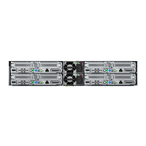
Page 76: Component Identification
Component identification Rear panel components Item Description Slot 1 PCIe3 x16 (16, 8, 4, 1) Slot 2 PCIe3 x16 (16, 8, 4, 1) or FlexibleLOM SUV port iLO Management Port iLO Service Port Media Module NIC port 2 Media Module NIC port 1 Serial number/iLO information pull tab USB 3.0 port If the RCM module is installed on the chassis, the iLO Management Port is automatically disabled. -
Page 77: Rear Panel Leds And Buttons
Rear panel LEDs and buttons Item Description Status Definition NIC link LED Green Linked to network No network link NIC status LED Flashing green Network active No network activity Health LED Solid green Normal Flashing green iLO is rebooting. Flashing amber System degraded Flashing red System critical... -
Page 78: Server Uid Led
The UID button can be used to display the Server Health Summary when the server will not power on. For more information, see the latest HPE iLO 5 User Guide on the Hewlett Packard Enterprise website. Front panel LED power fault codes The following table provides a list of power fault codes, and the subsystems that are affected. -
Page 79: Hpe Infiniband Hdr/Ethernet 940Qsfp 56X16 Adapter Leds
HPE InfiniBand HDR/Ethernet 940QSFP 56x16 adapter LEDs Link LED status Description A link has not been established. Solid amber Active physical link exists Blinking amber 4 Hz blinking amber indicates a problem with the physical link. Solid green A valid logical (data activity) link exists with no active traffic. -
Page 80: System Maintenance Switch Descriptions
Item Description Primary PCIe x16 riser connector 1 Media Module connector System battery OPA adapter sideband cable connector M.2 SSD riser connector Processor 1 DIMM slots for processor 1 Processor 2 DIMM slots for processor 2 Bayonet board connector Secondary PCIe x24 riser connector 4 Secondary PCIe x24 riser connector 3 x4 SATA port System maintenance switch... -
Page 81: Dimm Label Identification
Position Default Function — Reserved — Reserved — Reserved — Reserved To access the redundant ROM, set S1, S5, and S6 to On. When the system maintenance switch position 6 is set to the On position, the system is prepared to restore all configuration settings to their manufacturing defaults. - Page 82 R = RDIMM (registered) L = LRDIMM (load reduced) E = Unbuffered ECC (UDIMM) For more information about product features, specifications, options, configurations, and compatibility, see the HPE DDR4 SmartMemory QuickSpecs on the Hewlett Packard Enterprise website (https://www.hpe.com/support/ DDR4SmartMemoryQS). Component identification...
-
Page 83: Hpe Persistent Memory Module Label Identification
256 GB 512 GB QR code Includes part number and serial number For more information about product features, specifications, options, configurations, and compatibility, see the product QuickSpecs on the Hewlett Packard Enterprise website (https://www.hpe.com/support/persistentmemoryQS). Processor, heatsink, and socket components Component identification... -
Page 84: Bayonet Port Numbering
Item Description Heatsink nuts Processor carrier Pin 1 indicator Heatsink latch Alignment post Symbol also on the processor and frame. Bayonet port numbering PCIe riser board components This section identifies the riser slots compatible with specific types of expansion options supported by the server. The following riser options are supported: Primary riser •... -
Page 85: Secondary Riser Board Components
Item Slot number Description Supported option PCIe3 x16 (16, 8, 4, 1) • Smart Array type-p controller • Network adapter • OPA adapter • InfiniBand adapter — Storage controller backup power — connector Intel Omni-Path Architecture Secondary riser board components The server supports multiple riser options in the secondary position. - Page 86 P1 secondary riser board components Item Slot Description Supported options number — Storage controller backup power — connector Smart Array type-p controller PCIe3 x16 (16, 8, 4, 1) • • Low-profile expansion boards Auxiliary adapter • P2 secondary riser board components Processor 2 is required to support the P2 secondary riser option.
- Page 87 Item Slot number Description Supported options — Storage controller backup — power connector Smart Array type-p controller PCIe3 x16 (16, 8, 4, 1) • • Low-profile expansion boards • Auxiliary adapter P1/P2 secondary riser port numbering M.2 SSD riser bay numbering The arrow points toward the server release lever.
-
Page 88: Hpe Infiniband Hdr100/Ethernet 200 Gb 1-Port 940Qsfp56 X16 Adapter Component
HPE InfiniBand HDR100/Ethernet 200 GB 1-port 940QSFP56 x16 adapter component Item Description QSFP56 port Black cable connector White cable connector HPE InfiniBand HDR PCIe G3 Auxiliary card Item Description Black cable connector White cable connector Component identification... -
Page 89: Cabling
Cabling Cabling guidelines The cable colors in the cabling diagrams used in this chapter are for illustration purposes only. Most of the server cables are black. Observe the following guidelines when working with server cables. Before connecting cables • Note the port labels on the PCA components. Not all of these components are used by all servers: ◦... -
Page 90: Smart Array Cabling
• Remove cables that are no longer being used. Retaining them inside the server can restrict airflow. If you intend to use the removed cables later, label and store them for future use. Smart Array cabling Smart Array controller cables Controller type Cable kit part Cable part... -
Page 91: Onboard S100I Sr Gen10 Controller Cabling (Sata Only)
Onboard S100i SR Gen10 controller cabling (SATA only) Smart Array type-p controller cabling (SAS/SATA) Smart Array type-p controller cabling in the primary riser slot Cabling... -
Page 92: Storage Controller Backup Power Cabling
Smart Array type-p controller cabling in the secondary riser slot Storage controller backup power cabling Storage controller backup power cabling in the primary riser slot Storage controller backup power cabling in the P1 secondary riser Cabling... -
Page 93: Secondary Riser Cabling
Storage controller backup power cabling in the P2 secondary riser Secondary riser cabling Cabling matrix Cable kit part number Cable part number From # To port # 874304-B21 870531-001 Riser port 1 or 2 Bayonet port 1 or 2 870532-001 The 870531-001 cable included in the 874304-B21 cable kit is a 16NVMe long cable. -
Page 94: Flexiblelom Riser Cabling
FlexibleLOM riser cabling OPA adapter cabling Cable color Description Blue OPA adapter sideband cable Orange OPA adapter IFP cable Cabling... -
Page 95: Infiniband And Auxiliary Adapter Cabling
InfiniBand and auxiliary adapter cabling Cable color Description Orange White cable Blue Black cable Cabling... -
Page 96: Specifications
Specifications Environmental specifications Specification Value Temperature range — Operating 10°C to 35°C (50°F to 95°F) Non-operating -30°C to 60°C (-22°F to 140°F) Relative humidity (noncondensing) — Operating 8% to 90% 28°C (82.4°F), maximum wet bulb temperature Non-operating 5% to 95% 38.7°C (101.7°F), maximum wet bulb temperature All temperature ratings shown are for sea level. -
Page 97: List Of Components With Temperature Requirements
CAUTION: To reduce the risk of damage to the equipment when installing third-party options: • Do not permit optional equipment to impede airflow around the server or to increase the internal rack temperature beyond the maximum allowable limits. • Do not exceed the TMRA of manufacturer. •... - Page 98 • The processor does not support enhanced processor performance. • LFF drives with drive capacities greater than or equal to 10 TB are not supported for the Apollo r2200 Gen10 Chassis series with three drives per node. Description Chassis Fan configuration Number of drives Maximum inlet supported by the server...
- Page 99 Description Chassis Fan configuration Number of drives Maximum inlet supported by the server ambient temperature Apollo r2600 Gen10 Redundant and 0 to 6 drives 35°C (95°F) Chassis nonredundant (24 SFF or 16 SFF + 8 NVMe backplane) Apollo r2800 Gen10 Redundant and 0 to 24 drives 35°C (95°F)
- Page 100 Description Chassis Fan configuration Number of drives Maximum inlet ambient supported by the server temperature Apollo r2800 Redundant 0 to 4 drives 35°C (95°F) Gen10 Chassis (16 NVMe backplane) 64 GB LRDIMM Apollo r2200 Redundant 3 drives Not supported Gen10 Chassis 3 drives Not supported (12 LFF...
- Page 101 Description Chassis Fan configuration Number of drives Maximum inlet ambient supported by the server temperature Apollo r2800 Redundant and 0 to 4 drives Not supported Gen10 Chassis nonredundant (16 NVMe backplane) Apollo r2200 Redundant and 3 drives Not supported HPE Persistent Gen10 Chassis nonredundant Memory module...
- Page 102 Description Chassis Fan configuration Number of drives Maximum inlet ambient supported by the server temperature P408i-p Apollo r2200 Redundant and 3 drives Not supported Controller Gen10 Chassis nonredundant 3 drives Not supported (12 LFF 0 to 2 drives 28°C (82.4°F) backplane) Apollo r2600 Redundant and...
- Page 103 Description Chassis Fan configuration Number of drives Maximum inlet ambient supported by the server temperature 0 to 2 drives 35°C (95°F) (12 LFF backplane) Apollo r2600 Redundant and 0 to 6 drives 30°C (86°F) Gen10 Chassis nonredundant (24 SFF or 16 SFF + 8 NVMe backplane) Apollo r2800...
- Page 104 If the component is installed in server 1 or server 2, and the server is installed in the Apollo r2200 Gen10 Chassis, drive blanks must be installed in drive bays 1-2 and 2-2. Similarly, if the component is installed in server 3 or server 4, and the server is installed in the Apollo r2200 Gen10 Chassis, drive blanks must be installed in drive bays 3-2 and 4-2.
- Page 105 Description Chassis Fan configuration Number of drives Maximum inlet ambient supported by the server temperature Apollo r2800 Redundant and 0 to 24 drives Optical cable: Not Gen10 Chassis nonredundant supported (24 SFF Copper cable: 30°C (86°F) backplane with SAS expander) Apollo r2800 Redundant and 0 to 4 drives...
- Page 106 Description Chassis Fan configuration Number of drives Maximum inlet ambient supported by the server temperature Apollo r2800 Redundant and 0 to 4 drives Optical cable: Not Gen10 Chassis nonredundant supported (16 NVMe Using a copper cable: backplane) 30°C (86°F) Ethernet Apollo r2200 Redundant and 3 drives...
- Page 107 Description Chassis Fan configuration Number of drives Maximum inlet ambient supported by the server temperature 0 to 2 drives (24 SFF or 16 Optical cable: 22°C SFF + 8 NVMe (71.6°F) backplane) Copper cable: 28°C (82.4°F) Apollo r2800 Redundant and 0 to 24 drives Not supported Gen10 Chassis...
- Page 108 Description Chassis Fan configuration Number of drives Maximum inlet ambient supported by the server temperature IB HDR/EN 200 Apollo r2200 Redundant and 3 drives Not supported GB 1P Gen10 Chassis nonredundant 3 drives Not supported 940QSFP56 (12 LFF 0 to 2 drives Not supported backplane) 0 to 2 drives...
- Page 109 FlexibleLOM adapters with SFP+, SFP28 or QSFP transceivers Chassis Fan configuration Number of drives supported Maximum inlet ambient by the server temperature Apollo r2200 Gen10 Redundant and 3 drives Optical cable: Not supported Chassis nonredundant Copper cable: 28°C (82.4°F) (12 LFF backplane) 3 drives Not supported 0 to 2 drives...
-
Page 110: Thermal Limitations For Components In Systems With The Enhanced Processor Performance Feature Disabled
Description Chassis Fan configuration Number of drives Maximum inlet ambient supported by the server temperature Apollo r2800 Redundant and 0 to 24 drives 30°C (86°F) Gen10 Chassis nonredundant (24 SFF backplane with SAS expander) Apollo r2800 Redundant and 0 to 4 drives 30°C (86°F) Gen10 Chassis nonredundant... - Page 111 • The processor does not support enhanced processor performance. • LFF drives with drive capacities greater than or equal to 10 TB are not supported for the Apollo r2200 Gen10 Chassis series with three drives per node. Description Chassis Fan configuration Number of drives Maximum inlet supported by the server...
- Page 112 Description Chassis Fan configuration Number of drives Maximum inlet supported by the server ambient temperature Apollo r2800 Redundant and 0 to 24 drives 28°C (82.4°F) Gen10 Chassis nonredundant (24 SFF backplane with SAS expander) Apollo r2800 Redundant and 0 to 4 drives 30°C (86°F) Gen10 Chassis nonredundant...
- Page 113 Description Chassis Fan configuration Number of drives Maximum inlet ambient supported by the server temperature 64 GB LRDIMM Apollo r2200 Redundant 3 drives Not supported Gen10 Chassis 3 drives Not supported (12 LFF 0 to 2 drives 35°C (95°F) backplane) Apollo r2600 Redundant 0 to 6 drives...
- Page 114 Description Chassis Fan configuration Number of drives Maximum inlet ambient supported by the server temperature 0 to 2 drives Not supported (12 LFF backplane) 0 to 2 drives 25°C (77°F) Apollo r2600 Redundant and 0 to 6 drives Not supported Gen10 Chassis nonredundant 0 to 2 drives...
- Page 115 Description Chassis Fan configuration Number of drives Maximum inlet ambient supported by the server temperature Apollo r2600 Redundant and 0 to 6 drives 28°C (82.4°F) Gen10 Chassis nonredundant (24 SFF or 16 SFF + 8 NVMe backplane) Apollo r2800 Redundant and 0 to 24 drives 28°C (82.4°F) Gen10 Chassis...
- Page 116 Description Chassis Fan configuration Number of drives Maximum inlet ambient supported by the server temperature Apollo r2600 Redundant and 0 to 6 drives 35°C (95°F) Gen10 Chassis nonredundant (24 SFF or 16 SFF + 8 NVMe backplane) Apollo r2800 Redundant and 0 to 24 drives 35°C (95°F) Gen10 Chassis...
- Page 117 Fibre Channel and Converged Network adapters Description Chassis Fan configuration Number of drives Maximum inlet ambient supported by the server temperature FC HBA Apollo r2200 Redundant and 3 drives Not supported Gen10 Chassis nonredundant 3 drives Not supported (12 LFF 0 to 2 drives 28°C (82.4°F) backplane)
- Page 118 Description Chassis Fan configuration Number of drives Maximum inlet ambient supported by the server temperature Apollo r2800 Redundant and 0 to 24 drives Optical cable: 25°C (77°F) Gen10 Chassis nonredundant Copper cable: 35°C (95°F) (24 SFF backplane with SAS expander) Apollo r2800 Redundant and 0 to 4 drives...
- Page 119 Description Chassis Fan configuration Number of drives Maximum inlet ambient supported by the server temperature Apollo r2800 Redundant and 0 to 4 drives Optical cable: 25°C (77°F) Gen10 Chassis nonredundant Copper cable: 35°C (95°F) (16 NVMe backplane) Ethernet Apollo r2200 Redundant and 3 drives Optical cable: Not...
- Page 120 Description Chassis Fan configuration Number of drives Maximum inlet ambient supported by the server temperature 0 to 2 drives (24 SFF or 16 Optical cable: 25°C (77°F) SFF + 8 NVMe Copper cable: 30°C (86°F) backplane) Apollo r2800 Redundant and 0 to 24 drives Not supported Gen10 Chassis...
- Page 121 Description Chassis Fan configuration Number of drives Maximum inlet ambient supported by the server temperature 0 to 2 drives (12 LFF Optical cable: 25°C (77°F) backplane) Copper cable: 30°C (86°F) Apollo r2600 Redundant and 0 to 6 drives Not supported Gen10 Chassis nonredundant 0 to 2 drives...
- Page 122 FlexibleLOM adapters with SFP+, SFP28 or QSFP transceivers Chassis Fan configuration Number of drives supported Maximum inlet ambient by the server temperature Apollo r2200 Gen10 Redundant and nonredundant 3 drives Optical cable: Not supported Chassis Copper cable: 30°C (86°F) (12 LFF backplane) 3 drives Optical cable: Not supported Copper cable: 25°C (77°F)
- Page 123 Description Chassis Fan configuration Number of drives Maximum inlet ambient supported by the server temperature Apollo r2600 Redundant and 0 to 6 drives 35°C (95°F) Gen10 Chassis nonredundant (24 SFF or 16 SFF + 8 NVMe backplane) Apollo r2800 Redundant and 0 to 24 drives 35°C (95°F) Gen10 Chassis...
-
Page 124: Websites
Single Point of Connectivity Knowledge (SPOCK) Storage compatibility matrix www.hpe.com/storage/spock Storage white papers and analyst reports www.hpe.com/storage/whitepapers For additional general support websites, see Support and other resources. Product websites HPE ProLiant XL170r Gen10 support page https://www.hpe.com/info/Apollo2000-Gen10-docs HPE ProLiant XL170r Gen10 user documents https://www.hpe.com/info/XL170r-Gen10-UG-en Websites... -
Page 125: Support And Other Resources
• For live assistance, go to the Contact Hewlett Packard Enterprise Worldwide website: https://www.hpe.com/info/assistance • To access documentation and support services, go to the Hewlett Packard Enterprise Support Center website: https://www.hpe.com/support/hpesc Information to collect • Technical support registration number (if applicable) •... -
Page 126: Customer Self Repair
Customer self repair Hewlett Packard Enterprise customer self repair (CSR) programs allow you to repair your product. If a CSR part needs to be replaced, it will be shipped directly to you so that you can install it at your convenience. Some parts do not qualify for CSR. -
Page 127: Regulatory Information
Documentation feedback Hewlett Packard Enterprise is committed to providing documentation that meets your needs. To help us improve the documentation, send any errors, suggestions, or comments to Documentation Feedback (docsfeedback@hpe.com). When submitting your feedback, include the document title, part number, edition, and publication date located on the front cover of the document. - Page 128 Acronyms and abbreviations AHCI Advanced Host Controller Interface Customer Self Repair Converged Network Adapter FHHL Full Height Half Length FC HBA Fibre Channel Host Bus Adapter HPE APM HPE Apollo Platform Management HPE SSA HPE Smart Storage Administrator Integrated Lights-Out Integrated Management Log International Organization for Standardization Internal faceplate-to-processor...
- Page 129 power distribution unit POST Power-On Self-Test RBSU ROM-Based Setup Utility Rack Consolidation Management RoHS Restriction of Hazardous Substances serial attached SCSI SATA serial ATA small form factor Service Pack for ProLiant UEFI Unified Extensible Firmware Interface unit identification universal serial bus Acronyms and abbreviations...
Need help?
Do you have a question about the HPE ProLiant XL170r Gen10 and is the answer not in the manual?
Questions and answers