
Related Manuals for ADLINK Technology EOS-JNX-I


Summary of Contents for ADLINK Technology EOS-JNX-I
- Page 1 EOS-JNX-I / EOS-JNX-G Edge AI Vision Inference System User’s Manual Manual Rev.: February 17, 2022 Revision Date: 50M-00054-1010 Part No:...
- Page 2 Revision History Revision Release Date Description of Change(s) 2021-12-08 Initial Release Correct Front and Rear Panel I/O 2022-02-17 descriptions; add safety warning Revision History...
-
Page 3: Preface
EOS-JNX Series Preface Copyright © 2022 ADLINK Technology, Inc. This document contains proprietary information protected by copy- right. All rights are reserved. No part of this manual may be repro- duced by any mechanical, electronic, or other means in any form without prior written permission of the manufacturer. - Page 4 Conventions Take note of the following conventions used throughout this manual to make sure that users perform certain tasks and instructions properly. Additional information, aids, and tips that help users perform tasks. NOTE: NOTE: Information to prevent minor physical injury, component dam- age, data loss, and/or program corruption when trying to com- plete a task.
-
Page 5: Table Of Contents
EOS-JNX Series Table of Contents Revision History..............ii Preface ..................iii List of Tables................. vii List of Figures ................ ix 1 Introduction ................ 1 Features................1 Specifications............... 2 Mechanical Dimensions............4 External Layout..............6 Pin Definitions..............9 1.5.1 RJ45 LAN/PoE Connectors ........9 1.5.2 PoE LED.............. - Page 6 2.3.3 Installing an M.2 2230 Module (Optional) ....27 2.3.4 Installing an Internal USB Device (Optional) .... 29 Front Panel I/O Connection ..........30 2.4.1 Connecting General Input/Output Ports....30 2.4.2 Connecting PoE Camera .......... 31 2.4.3 Digital I/O Connection..........32 2.4.4 Connecting DC Power ..........
-
Page 7: List Of Tables
EOS-JNX Series List of Tables Table 1-1: Specifications ............. 2 Table 1-2: Front Panel I/O Connectors & Controls ...... 6 Table 1-3: Rear Panel I/O Connectors ........8 Table 1-4: RJ45 LAN/PoE Connector Pin Definition....9 Table 1-5: PoE LAN/Uplink Port Connector Definition....10 Table 1-6: PoE/Uplink LAN LED Connection Status .... - Page 8 This page intentionally left blank. viii List of Tables...
-
Page 9: List Of Figures
EOS-JNX Series List of Figures Figure 1-1: EOS-JNX-I Front View..........4 Figure 1-2: EOS-JNX-I Side View..........4 Figure 1-3: EOS-JNX-G Front View..........5 Figure 1-4: EOS-JNX-G Side View ..........5 Figure 1-5: Front Panel I/O Connectors........6 Figure 1-6: Rear Panel I/O Connectors ........8 Figure 2-1: Installing an M.2 SSD Module/USB dongle .... - Page 10 This page intentionally left blank. List of Figures...
-
Page 11: Introduction
EOS-JNX Series Introduction ADLINK’s EOS-JNX (-I/-G) Series leverages the power of an NVIDIA® Jetson Xavier™ module to deliver artificial intelligence (AI) at the edge, and provides PoE switch functionality for IP cam- era (-I) or GigE camera (-G) connections. The EOS-JNX Edge AI platforms with integrated NVIDIA Jetson Xavier NX accelerates deep learning workloads for object detection, recognition, and classification suitable for industrial embedded applications such as... -
Page 12: Specifications
1.2 Specifications Model EOS-JNX-I EOS-JNX-G System Core Platform NVIDIA® Jetson Xavier™ NX 6-core NVIDIA Carmel ARM® v8.2 64-bit CPU Processor 6 MB L2 + 4 MB L3 NVIDIA Volta architecture with 384 NVIDIA CUDA® cores and 48 Tensor cores Memory... - Page 13 EOS-JNX Series Model EOS-JNX-I EOS-JNX-G Power DC Input DC 12 to 24V Fail Reset Reset and Recovery buttons PoE Switch PoE initial mode setup Mechanical Dimensions 187.5(W) x 149.5(D) x 55.25(H) mm Weight 1.85 kg Mounting supports wall mount & DIN rail mount Environmental Standard: -20°C to 50°C (w/ 0.6m/s airflow)
-
Page 14: Mechanical Dimensions
1.3 Mechanical Dimensions All dimensions shown in millimeters (mm). 187.50 Figure 1-1: EOS-JNX-I Front View 149.50 Figure 1-2: EOS-JNX-I Side View Introduction... -
Page 15: Figure 1-3: Eos-Jnx-G Front View
EOS-JNX Series 187.50 Figure 1-3: EOS-JNX-G Front View 149.50 Figure 1-4: EOS-JNX-G Side View Introduction... -
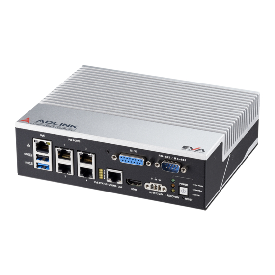
Page 16: External Layout
60W. PoE Status LED PoE port enabled status. NVR (Network Video Recorder) connection for PoE IP cameras (EOS-JNX-I only). Uplink Port Maximum bandwidth: 1Gbps. (EOS-JNX-I only) Note: The Uplink Port (E) cannot be used as an Ethernet connection. - Page 17 EOS-JNX Series Item Name Description Press recovery button and reset button at the same Recovery Button time to trigger recovery mode. See 3.3 System Recovery on page 38. RS-232/485 Port Supports RS-232/485 connectivity and control. Shows system operation status Green •...
-
Page 18: Table 1-3: Rear Panel I/O Connectors
• EOS-JNX-G enables PoE after user presses the Power button PoE Switch • EOS-JNX-I enables PoE when DC power is on • Initial PoE status of both models is disabled and PoE On/Off status is controlled by the AVS SDK. -
Page 19: Pin Definitions
EOS-JNX Series 1.5 Pin Definitions 1.5.1 RJ45 LAN/PoE Connectors Pin No. Function Description BI_DA+ Bi-directional pair A+ BI_DA- Bi-directional pair A- BI_DB+ Bi-directional pair B+ BI_DB- Bi-directional pair C+ BI_DC+ Bi-directional pair C- BI_DC- Bi-directional pair B- BI_DD+ Bi-directional pair D+ BI_DD- Bi-directional pair D- Table 1-4: RJ45 LAN/PoE Connector Pin Definition... -
Page 20: Table 1-5: Poe Lan/Uplink Port Connector Definition
EOS-JNX-I LAN/PoE/Uplink Connectors Port Description PoE LAN 1-4 Bandwidth: 10/100Mbps, for PoE IP CAM connection Uplink (EOS-JNX-I only) Bandwidth: 1Gbps, for external NVR connection Table 1-5: PoE LAN/Uplink Port Connector Definition PoE/Uplink LAN LED connection status: Left LED Right LED... -
Page 21: Table 1-7: Gige Lan Led Connection Status
EOS-JNX Series GigE LAN LED connection status: Left LED (Green) Right LED (Yelllow) LINK Table 1-7: GigE LAN LED Connection Status EOS-JNX-G LAN/PoE Connectors Port Description PoE LAN 1-4 Bandwidth: 10/100/1000 Mbps, for PoE GigE CAM connection. Table 1-8: EOS-JNX-G PoE LAN Port Connector Definition PoE LAN LED connection status: Left LED Right LED... -
Page 22: Poe Led
GigE LAN LED connection status: Left LED Right LED (Green) (Yelllow) LINK Table 1-10: GigE LAN LED Connection Status 1.5.2 PoE LED Status (Yellow) ON: LAN 1 PoE On OFF: LAN 1 PoE Off ON: LAN 2 PoE On OFF: LAN 2 PoE Off ON: LAN 3 PoE On OFF: LAN 3 PoE Off ON: LAN 4 PoE On... -
Page 23: Table 1-13: Usb 3.0 Type-A Connector Pin Definition
EOS-JNX Series USB 3.0 Type-A Connector Pin No. Signal VBUS StdA_SSRX− StdA_SSRX+ GND_DRAIN StdA_SSTX− StdA_SSTX+ Table 1-13: USB 3.0 Type-A Connector Pin Definition Introduction... -
Page 24: D-Sub 15-Pin Di/O Connector (Female)
1.5.4 D-sub 15-pin DI/O Connector (Female) Pin No. Function IGND General Purpose DO0 General Purpose DO1 General Purpose DO2 General Purpose DO3 WatchDog Alarm DO IGND General Purpose DI0 General Purpose DI1 General Purpose DI2 General Purpose DI3 Table 1-14: D-sub 15-pin DI/O Connector Pin Definition Introduction... -
Page 25: Hdmi Connector
EOS-JNX Series 1.5.5 HDMI Connector The HDMI connector supports HDMI 1.4. Pin # Signal Pin # Signal TMDS Data2+ TMDS Data2 Shield TMDS Data2– TMDS Data1+ TMDS Data1 Shield TMDS Data1– TMDS Data0+ TMDS Data0 Shield TMDS Data0– TMDS Clock+ TMDS Clock Shield TMDS Clock–... -
Page 26: Dc Power Connector
1.5.6 DC Power Connector The system requires a 12-24V DC power source with a screw-type connector. Pin No. Function V+ Power Chassis GND V- Ground Table 1-16: DC Power Connector Pin Definition Introduction... -
Page 27: D-Sub 9-Pin Rs-232/485 Connector (Male)
EOS-JNX Series 1.5.7 D-sub 9-pin RS-232/485 Connector (Male) Function Pin No. RS-232 RS-485 Data- Data+ Table 1-17: D-sub 9-pin RS-232/485 Connector Pin Definition 1.5.8 Front Panel System Status LED Status Green System Ready WatchDog Alarm Yellow Standby power ready Table 1-18: Front Panel System Status LED Introduction... -
Page 28: Wafer Connector (2.0Mm Pin Pitch)
1.6 Wafer Connector (2.0mm Pin Pitch) Pin No. Function Description Debug UART2_RX RX channel of debug UART port Debug UART2_TX TX channel of debug UART port RESET_IN# System reset Digital Ground Force Recovery Strap Pin FORCE_RECOV# (System Recovery Mode) Digital Ground Digital Ground Digital Ground Table 1-19: Wafer Connector Pin Definition... -
Page 29: Usb Micro-A Connector
EOS-JNX Series 1.7 USB Micro-A Connector Pin No. Function Description Power Input DC 5V USB 2.0 Data - USB 2.0 bi-directional pair - USB 2.0 Data + USB 2.0 bi-directional pair + No Connection Digital Ground No Connection Digital Ground No Connection Digital Ground Table 1-20: USB Micro-A Connector Pin Definition... - Page 30 This page intentionally left blank. Introduction...
-
Page 31: Getting Started
EOS-JNX Series Getting Started 2.1 Unpacking Checklist Before unpacking, check the shipping carton for any damage. If the shipping carton and/or contents are damaged, inform your dealer immediately. Retain the shipping carton and packing materials for inspection. Obtain authorization from your dealer before returning any product to ADLINK. -
Page 32: Internal Storage Installation (Optional)
2.3 Internal Storage Installation (Optional) 2.3.1 Removing the Chassis Cover Follow the instructions below to remove the chassis top cover. All installation procedures are restricted to skilled personnel. Mise en garde: Toutes les procédures d'installation sont CAUTION: réservées au personnel qualifié. To access the EOS-JNX internal components, remove the under- side of the chassis as follows. - Page 33 EOS-JNX Series 2. Slide the cover in the direction indicated. Getting Started...
- Page 34 3. Lift the cover off of the chassis. Reverse the steps to replace the bottom cover. Getting Started...
-
Page 35: Installing An M.2 Ssd Module/Usb Dongle
EOS-JNX Series 2.3.2 Installing an M.2 SSD Module/USB Dongle Use the following steps to install an M.2 SSD module or USB dongle. 1. Install a suitable storage device, as shown. Supports M.2-2280, B+M Key, PCI-E Supports USB 2.0 dongle Supports M.2-2230, A+E Key, PCI-E/USB2.0 Thermal Pad (bottom) to... - Page 36 2. Skip this step if the EOS-JNX will not be used in a shock/vibra- tion environment. For M.2-2280 slot installation, apply 2 ther- mal interface material (TIM) pads on the PCBA before installing the M.2 2280 module. Apply 1 long TIM pad on the underside of the rear cover along the aligned marks, as shown.
-
Page 37: Installing An M.2 2230 Module (Optional)
EOS-JNX Series 2.3.3 Installing an M.2 2230 Module (Optional) Use the following steps to install an M.2 2230 module or USB dongle. 1. Insert 4 cable clips (included in screw pack) as shown (2 each from the top and underside of the mainboard). Figure 2-2: Installing M.2 2230 Module Cable Clips Getting Started... -
Page 38: Figure 2-3: M.2 2230 Module Cable Routing
2. Install an M.2 2230 module device. 3. Route cabling as shown. Figure 2-3: M.2 2230 Module Cable Routing Getting Started... -
Page 39: Installing An Internal Usb Device (Optional)
EOS-JNX Series 2.3.4 Installing an Internal USB Device (Optional) The EOS-JNX has a reserved USB 2.0 slot for an additional internal USB dongle device that can be used for license protection. Use the sponge piece provided in the screw pack and and install as shown. Figure 2-4: Installing Internal USB Device (Optional) Figure 2-5: USB Device Sponges (Optional) Getting Started... -
Page 40: Front Panel I/O Connection
(D-sub 15-pin Female) (D-sub 9-pin Male) 1x USB 2.0 4x PoE Ports Uplink Port HDMI Port DC-In 1x USB 3.0 (EOS-JNX-I only) KB/MS IP CAM GigE CAM Display 2.4.1 Connecting General Input/Output Ports Ethernet LAN port for network connection USB input devices like keyboard/mouse. or other USB... -
Page 41: Connecting Poe Camera
Connecting PoE Camera EOS-JNX series PoE ports support PoE interface cameras. Select the right EOS-JNX model for the camera being used. EOS-JNX-I PoE port bandwidth supports IP cameras (10M/ 100M), and the uplink port supports NVR (Network Video Recorder) connection. -
Page 42: Digital I/O Connection
2.4.3 Digital I/O Connection External devices such as trigger sensors, LED light controllers or relays can be connected to the EOS-JNX to implement different applications. The figures below show of how to connect these kinds of devices. ADLINK also provides a DI/O cable (P/N: 30- 01332-0010-A0) and a DIN37 termination board (P/N: 91-14025- 1020) for DI/O applications. -
Page 43: Connecting Dc Power
EOS-JNX Series 2.4.4 Connecting DC Power Before providing DC power to the EOS-JNX, ensure the volt- age and polarity provided are compatible with the DC input. Improper input voltage and/or polarity can be responsible for WARNING: system damage. Avant de connecter le PC EOS-JNX à une source de courant continu, veuillez vous assurer de la polarité... -
Page 44: Wall Mount (Optional)
2.5 Wall Mount (Optional) An optional wall mount kit is available for the EOS-JNX. Refer to the product datasheet or website for ordering information. Follow the steps below to mount the device to a wall. 1. Attach the brackets to a wall (or other suitable mounting surface) so that their keyhole-shaped mounting holes are oriented with the wider openings at the top. -
Page 45: Din Rail Mount
EOS-JNX Series 2.6 DIN Rail Mount An optional DIN rail mount kit is available for the EOS-JNX. with its own M4 screws. Use two M4 screws to attach the DIN rail bracket to the EOS-JNX as shown. M4 x6mm Screw Figure 2-9: DIN Rail Mount Getting Started... - Page 46 This page intentionally left blank. Getting Started...
-
Page 47: Using The System
EOS-JNX Series Using the System 3.1 Software Configuration The EOS-JNX ships with a customized software image prein- stalled. The software configuration includes: NVIDIA Jetpack Basler Pylon AVS SDK Edge Vision Analytics (EVA) SDK ONNXRuntime RS-232/485 ConfigManager Watchdog ConfigManager Retrieve RTSP URL from ONVIF service ONVIF Discovery service VLAN Configuration tool Software application versions may not be up-to-date and... -
Page 48: System Recovery
3.3 System Recovery You will need a Linux host PC (Ubuntu is recommended) in order to flash your client device with a new system image. Complete the following steps on the client before performing the host PC steps. 1. Press the power button to turn on the system. 2. -
Page 49: Important Safety Instructions
EOS-JNX Series Important Safety Instructions For user safety, please read and follow all instructions, Warnings, Cautions, and Notes marked in this manual and on the associated device before handling/operating the device, to avoid injury or damage. Read these safety instructions carefully. Keep the User’s Manual for future reference. - Page 50 Never attempt to repair the device, which should only be ser- viced by qualified technical personnel using suitable tools The device must be serviced by authorized technicians when: The power cord or plug is damaged. Liquid has entered the device interior. The device has been exposed to high humidity and/or moisture.
- Page 51 EOS-JNX Series Lisez attentivement ces consignes de sécurité Conservez le manuel de l'utilisateur pour pouvoir le con- sulter ultérieurement Lisez la section Spécifications de ce manuel pour des infor- mations détaillées sur l'environnement d'exploitation recom- mandé L'appareil peut fonctionner à une température ambiante de 70°C avec un débit d'air de 0,6 ms.
- Page 52 Si l'appareil ne doit pas être utilisé pendant de longues péri- odes, éteignez-le et débranchez-le de sa source d'alimentation N'essayez jamais de réparer l'appareil, qui ne doit être réparé que par un personnel technique qualifié à l'aide d'outils appropriés L'appareil doit être entretenu par des techniciens agrees lorsque: Le cordon d’alimentation ou la prise est endommagé(e) Un liquide a pénétré...
-
Page 53: Getting Service
D-68163 Mannheim, Germany Tel: +49-621-43214-0 Fax: +49-621 43214-30 Email: emea@adlinktech.com ADLINK Technology, Inc. (UK Liaison Office) First Floor West Exeter House, Chichester Fields Business Park Tangmere, West Sussex, PO20 2FU, United Kingdom Tel: +44-1243-859677 Email: uk@adlinktech.com Please visit the Contact page at www.adlinktech.com...
Need help?
Do you have a question about the EOS-JNX-I and is the answer not in the manual?
Questions and answers