
Related Manuals for ADLINK Technology PCI-7432


Summary of Contents for ADLINK Technology PCI-7432
- Page 1 PCI-7432 / 7433 / 7434 cPCI-7432 / 7433 / 7434 64 Channels Isolated Digital I/O / Digital Input / Digital Output Card...
- Page 3 NuDAQ , NuIPC , PCI-7432, PCI-7433, PCI-7434, cPCI-7432, cPCI-7433, cPCI-7434 are registered trademarks of ADLink Technology Co., Ltd. Other product names mentioned herein are used for identification purposes only and may be trademarks and/or registered trademarks of their respective companies.
-
Page 4: Table Of Contents
PCI slot selection ..............9 2.5.3 Installation Procedures............9 2.5.4 Running the 7432UTIL.EXE ..........9 2.6 Connector Pin Assignment of PCI-7432........ 10 2.7 Connector Pin Assignment of PCI-7433........ 11 2.8 Connector Pin Assignment of PCI-7434........ 12 REGISTER FORMAT & CONNECTION ......REGISTER FORMAT & CONNECTION ...... - Page 5 PRODUCT WARRANTY/SERVICE ..............31 ii • • Contents...
-
Page 6: Introduction
Introduction The PCI-7432 provides 64 isolated digital I/O (32 Isolated inputs and 32 isolated outputs), PCI-7433 provides 64 isolated digital input and PCI-7434 provides 64 isolated digital output. The isolated I/O channels are isolated to 5000 Vdc (excluding cables), both channel-to-channel and channel-to-computer. It protects your computer against damage caused by accidental contact with high external voltage and elimates troublesome ground loops. -
Page 7: Features
For the customers who are writing their own programs, the PCI-7432/33/34 are supported by a comprehensive set of drivers and programming tools. These software supports are available in multiple platform. .C/C++ program library for MS-DOS and DLL library for Window 95, shipped with board. -
Page 8: Applications
500mA max. Isolated voltage: 5000 Vdc Throughput: 10K Hz • Interrupt sources (for PCI-7432/7433) Channel 0 and channel 1 of digital input channels ♦ General Specifications • Connector : 100-pin SCSI-II connector • Operating Temperature : 0° C ~ 60° C •... - Page 9 8PCI-7432: +5V @ 530 mA typical 8PCI-7433: +5V @ 500 mA typical 8PCI-7434: +5V @ 560 mA typical 8cPCI-7432: +5V @ 455 mA typical 8cPCI-7433: +5V @ 500 mA typical 8cPCI-7434: +5V @ 430 mA typical • Dimension : 8PCI-7432/33/34: Compact size only 98mm(H) X 173mm(L) 8cPCI-7432/33/34: Standard 3U CompactPCI form factor 4 •...
-
Page 10: Installation
Installation Installation This chapter describes the configurations of the PCI-7432/33/34 and teaches users to install the PCI-7432/33/34. At first, the contents in the package and unpacking information that you should care about are described. The PCI-7432/33/34 are plug- and-play; it is very easy to install into any PC system with PCI slots. -
Page 11: Unpacking
IC's to make sure that they are properly seated. Do this only with the module place on a firm flat surface. Note :DO NOT APPLY POWER TO THE CARD IF IT HAS BEEN DAMAGED. Now you are ready to install your PCI-7432/33/34 card. 6 • • Installation... -
Page 12: Device Installation For Windows 95
2.3 Device Installation for Windows 95 While you first plug PCI-7432/7433/7434 card and enter Windows 95, the system will detect this device automatically and show the following dialog box that prompts you to select the device information source. Choose the default option “Driver from disk provided by hardware manufacturer”... -
Page 13: Pci-7432/33/34'S Layout
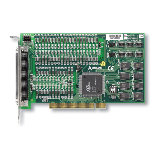
“7434.inf”) in the input field (X indicates the CD ROM driver) and then click OK. The system will start the installation of PCI- 7432/33/34 device. 2.4 PCI-7432/33/34's Layout PCI-7432/33/34’s layout are quite alike. The following is PCI- 7432’s layout. PCI Connector Chip Figure 2.1... -
Page 14: Pci-7432/33/34 Installation Outline
2.5 PCI-7432/33/34 Installation Outline 2.5.1 Hardware configuration PCI-7432/33/34 support plug and play, the card can requests memory usage (I/O port locations) assigned by system BIOS. The address assignment is done on a board-by-board basis for all PCI-7432/33/34 in the system. -
Page 15: Connector Pin Assignment Of Pci-7432
2.6 Connector Pin Assignment of PCI-7432 The pin assignment of the 100 pins SCSI-II connector is an isolated signal connector, PCI-7432’s pin assignment is as shown in Figure 2.7. (51) (52) (53) (1) IDI_0 (26) IDO_0 (51) IDI_8 (76) IDO_8... -
Page 16: Connector Pin Assignment Of Pci-7433
2.7 Connector Pin Assignment of PCI-7433 The pin assignment of the 100 pins SCSI-II connector is an isolated signal connector, PCI-7433’s pin assignment is as shown in Figure 2.8. (51) (1) IDI_0 (26) IDI_32 (51) IDI_8 (76) IDI_40 (52) (2) IDI_1 (27) IDI_33 (52) IDI_9 (77) IDI_41... -
Page 17: Connector Pin Assignment Of Pci-7434
2.8 Connector Pin Assignment of PCI-7434 The pin assignment of the 100 pins SCSI-II connector is an isolated signal connector, PCI-7434’s pin assignment is as shown in Figure 2.9. (51) (1) IDO_0 (26) IDO_32 (51) IDO_8 (76) IDO_40 (52) (53) (2) IDO_1 (27) IDO_33 (52) IDO_9... -
Page 18: Register Format & Connection
Register Format & Register Format & Connection Connection In this chapter, a primitive digital I/O operations of PCI-743X products will be specified. The I/O operations are also included. 3.1 I/O Port Base Address The PCI-743X or cPCI-743X function as a 32-bit PCI target (slave) device to any master on the PCI bus. -
Page 19: Digital Input Register
8-bit or 16-bit I/O access is not allowed. 3.2 Digital Input Register There are 32 isolated digital input channels on PCI-7432 and 64 isolated digital input channels on the PCI-7433, each bit of based address is corresponding to a signal on the digital input channel. -
Page 20: Digital Output Register
IDI_N : Isolated Digital Input CH N 3.3 Digital Output Register There are total 32 digital output channels on the PCI-7432 and 64 isolated digital input channels on the PCI-7434, each bit of based address is corresponding to a signal on the digital output channel. -
Page 21: Isolated Digital Input Channels
The isolated digital input is open collector transistor structure. The input voltage range form 5V to 24V and input resister is 1.2K Ω. The connection between outside signal and PCI-7432/33 is shown below. Please note that the input common junction could be common ground or common power, they are dependent on the user’s... -
Page 22: Isolated Digital Output Channels
3.5 Isolated Digital Output Channels The connection of isolated-digital output is shown as following diagram. When the isolated digital output goes “ON”, the sink current will be conducted through the transistors. When the isolated digital output goes “OFF”, no current could flow through the transistor. -
Page 24: C/C++ Libraries
C/C++ Libraries C/C++ Libraries In this chapter, the PCI-7432/33/34's software library, C/C++ language library, for DOS is described. 4.1 Installation 4.1.1 Installation The PCI-7432/33/34 Software Library supplied with PCI- 7432/33/34 includes a DOS utility software, C-language library and some demonstration programs which can help you reduce programming work. - Page 25 4. An installation complete message will be shown on the screen. After installation, all the files of PCI-7432/33/34 Library & Utility stored C:\ADLink\7432\DOS C:\ADLink\7433\DOS or C:\ADLink\7434\DOS directory. ♦ ♦ Windows 95 Software Installation step 1. Place the ADLink’s “Manual & Software Utility” CD into the appropriate CD driver.
- Page 26 Then you can click Next to begin installing PCI-7432/33/34 DLL for Windows 95. After you complete the installation of PCI-7432/33/34 Software, PCI-7432/33/34’s DLL (7432.DLL, 7433.DLL, or 7434.DLL) is copied Windows System directory (default C:\WINDOWS\SYSTEM), and the driver files (PCIW95.VXD, W95_7432.VXD or W95_7433.VXD) are also copied to the appropriate directory.
-
Page 27: Running Testing Utility (7432Util.exe)
(If your PCI card is PCI-7433 or 7434,please execute 7433UTIL.EXE or 7434UTIL.EXE) 4.3 I_EEPROM This utility is used to enable or disable the interrupt of PCI-7432/33 board. This software is a text-driven program. Because the default interrupt on PCI-7432/33 board is “off”, users who want to use interrupt function can use this utility to turn on the interrupt of their PCI-7432/33 board. -
Page 28: Software Driver Naming Convention
4.4 Software Driver Naming Convention The functions of PCI-7432/33/34's software drivers are using full- names to represent the functions' real meaning. The naming convention rules are: In DOS Environment : _{hardware_model}_{action_name}. e.g. _7432_Initial (). The detail descriptions of each function are specified in the following sections. -
Page 29: 7432_Di / _7433_Di_Hidw / _7433_Di_Lodw
@ Description This function is used to read 32-bit digital inputs data from digital input port. You can get 32 bits data from PCI-7432 by using function “_7432_DI”, get 32 bits data (MSB double word) from PCI-7433 by using “7433_DI_HiDW”, get 32 bits data (LSB double word) from PCI-7433 by using “7433_DI_LoDW”. -
Page 30: 7432_Do / _7434_Do_Hidw / _7434_Do_Lodw
4.7 _7432_DO / _7434_DO_HiDW / _7434_DO_LoDW @ Description This function is used to write data to digital output ports. There are 32 isolated digital outputs on the PCI-7432 and 64 isolated digital outputs on the PCI-7434, C/C++ Libraries • • 25... - Page 31 @ Syntax PCI-7432 C/C++ ( DOS) U16 _7432_DO (U16 cardNo, U32 do_data) C/C++ (Windows 95) U16 W_7432_DO (U16 cardNo, U32 do_data) Visual Basic (Windows 95) W_7432_DO (ByVal cardNo As Integer, ByVal do_data As Long) As Integer PCI-7434 C/C++ ( DOS)
-
Page 32: 7432_Set_Int_Control / _7433_Set_Int_Control
4.8 _7432_Set_INT_Control / _7433_Set_INT_Control @ Description The PCI-7432 or PCI-7433 has dual interrupts system, two interrupt sources can be generated and be checked by the software. This function is used to select and control PCI- 7432/33 interrupt sources by writing data to interrupt control register. -
Page 33: 7432_Get_Int_Status / _7433_Get_Int_Status
4.9 _7432_Get_INT_Status / _7433_Get_INT_Status @ Description The PCI-7432 or PCI-7433 has dual interrupts system. Two interrupt sources can be generated and be checked by the software. This function is used to distinguish which interrupt is inserted if both INT1 and INT2 interrupts are used. -
Page 34: 7432_Int_Enable / _7433_Int_Enable
When the event is signaled, it means an interrupt is generated. Please refer to the sample program 7432int.c or 7433int.c. @ Syntax PCI-7432 C/C++ (Windows 95) W_7432_INT_Enable (U16 cardNo, HANDLE *hEvent) Visual Basic (Windows 95) -
Page 35: 7432_Int_Disable / _7433_Int_Disable
@ Description This function is only available in Windows 95 driver. This function is used to disable the interrupt signal generation. @ Syntax PCI-7432 C/C++ (Windows 95) U16 W_7432_INT_Disable (U16 cardNo) Visual Basic (Windows 95) W_7432_INT_Disable (ByVal cardNo As Integer) As... - Page 36 Product Warranty/Service Seller warrants that equipment furnished will be free form defects in material and workmanship for a period of one year from the confirmed date of purchase of the original buyer and that upon written notice of any such defect, Seller will, at its option, repair or replace the defective item under the terms of this warranty, subject to the provisions and specific exclusions listed herein.
Need help?
Do you have a question about the PCI-7432 and is the answer not in the manual?
Questions and answers