VAT 590 Series Installation, Operating, & Maintenance Instructions
Variable leak valve dn 16 (5/8") with integrated controller with rs232 interface
Hide thumbs
Also See for 590 Series:
Table of Contents
Advertisement
Quick Links
Installation, Operating &
Maintenance Instructions
Variable leak valve DN 16 (5/8")
with integrated controller
with RS232 interface
Series 590
DN 16 mm (I.D. 5/8")
This manual is valid for the following product ordering number:
59024-.EGG-....
configured with firmware 600P.1G.21.00
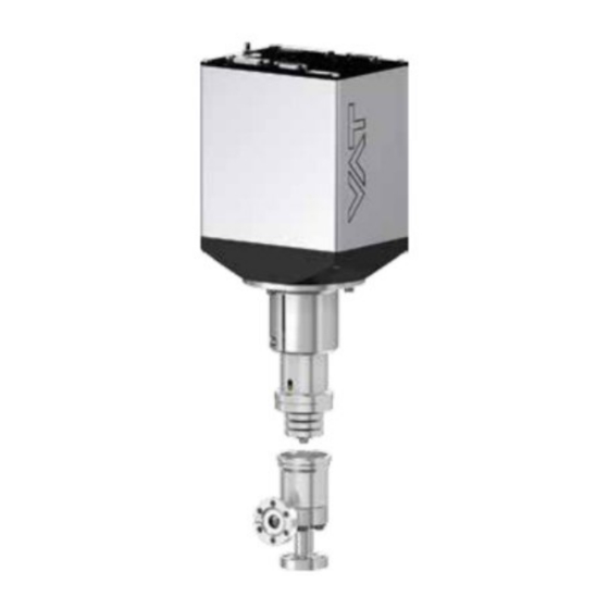
Sample picture
820655EA
Edition 2015-12-02
Advertisement
Table of Contents

Related Manuals for VAT 590 Series


Summary of Contents for VAT 590 Series
- Page 1 Installation, Operating & Maintenance Instructions Variable leak valve DN 16 (5/8") with integrated controller with RS232 interface Series 590 DN 16 mm (I.D. 5/8") This manual is valid for the following product ordering number: 59024-.EGG-…. configured with firmware 600P.1G.21.00 Sample picture 820655EA Edition 2015-12-02...
- Page 2 The VAT firmware may not be used for purposes other than those intended nor is it permitted to make copies of the VAT firmware. In particular, it is strictly forbidden to give copies of the VAT firmware to other people.
-
Page 3: Table Of Contents
Series 590 Contents Description of product ................ 5 Identification of product ....................5 Use of product ......................... 5 Used abbreviations ......................5 Related documents......................5 Important information....................... 5 Technical data ......................... 6 1.6.1 Control and actuating unit .................. 6 1.6.2 Valve unit ...................... - Page 4 Series 590 RS232 interface commands ..................37 4.7.1 RS232 command syntax .................. 37 4.7.2 Control commands ................... 37 4.7.3 Inquiry commands .................... 38 4.7.4 Position Limit open (setup command) .............. 42 4.7.5 Setup commands ..................... 43 4.7.5.1 Overview pressure controller ............50 4.7.6 Pressure control algorithem ................
-
Page 5: Description Of Product
Control Performance Analyzer Related documents • Product data sheet • Dimensional drawing Important information This symbol points to a very important statement that requires particular attention. Example: VAT disclaims any liability for damages resulting from inappropriate packaging. 820655EA Edition 2015-12-02 5/77... -
Page 6: Technical Data
DESCRIPTION OF PRODUCT Series 590 Technical data 1.6.1 Control and actuating unit Description Input voltage +24 VDC (±10%) @ 0.5 V pk-pk max. [connector: POWER] Power consumption 38 W [connector: POWER] Sensor power supply output +24 VDC / 1500 mA max. [connector: SENSOR] Sensor input Signal input voltage / Input resistance... -
Page 7: Valve Unit
Series 590 DESCRIPTION OF PRODUCT 1.6.2 Valve unit Please refer to Product data sheet. 820655EA Edition 2015-12-02 7/77... -
Page 8: Safety
SAFETY Series 590 Safety Compulsory reading material Read this chapter prior to performing any work with or on the product. It contains important information that is significant for your own personal safety. This chapter must have been read and understood by all persons who perform any kind of work with or on the product during any stage of its serviceable life. -
Page 9: Personnel Qualifications
Series 590 SAFETY Personnel qualifications WARNING Unqualified personnel Inappropriate handling may cause serious injury or property damage. Only qualified personnel are allowed to carry out the described work. 820655EA Edition 2015-12-02 9/77... -
Page 10: Design And Function
DESIGN AND FUNCTION Series 590 Design and Function Design open closed mechanical position indicator Function The valve plate acts as a throttling element and varies the conductance of the valve opening. Actuation is performed with a stepper motor and controller. The stepper motor/controller version ensures accurate pressure control due to exact gate positioning. -
Page 11: Installation
Make sure that the supplied products are in accordance with your order. • Inspect the quality of the supplied products visually. If it does not meet your requirements, please contact VAT immediately. • Store the original packaging material. It may be useful if products must be returned to VAT. -
Page 12: Installation Into The System
INSTALLATION Series 590 Installation into the system NOTICE Sealing surfaces Sealing surfaces of valve and vacuum system could be damage in case of incorrect handling. Only qualified personal are allowed to install the valve into the vacuum system. NOTICE Wrong connection Wrong connection may result in damage of controller or power supply. -
Page 13: Installation Space Condition
Series 590 INSTALLATION 4.2.1 Installation space condition Install the valve with integrated controller with space for dismantling and air circulation as shown in figure below. 820655EA Edition 2015-12-02 13/77... -
Page 14: Connection Overview
INSTALLATION Series 590 4.2.2 Connection overview System: Valve Process chamber Gas inlet Controller Pressure sensor Sensor cable Cable to remote control unit (RS232) Cable to power supply Pump Controller: 14/77 Edition 2015-12-02 820655EA... -
Page 15: Installation Procedure
Series 590 INSTALLATION 4.2.3 Installation procedure 1. Remove protection flanges only prior assembly into the vacuum system. 2. Install valve [1] into the vacuum system. • The valve seat side is indicated by the symbol «∆» on dimensional drawing, see also «Installation space condition». -
Page 16: Electrical Connection
INSTALLATION Series 590 Electrical connection NOTICE Wrong connection Wrong connection may result in damage of controller or power supply. Connect all cables exactly as shown in the following descriptions and schematics. NOTICE Burned connector pins (spark) Connector pins or electronic parts could damage, if plugged and unplugged under power. -
Page 17: Ground Connection
Series 590 INSTALLATION 4.3.1 Ground connection Recommendation for ground strap between controller and system (chassis) ∅ ∅ Material L (Length max.) B1 (min.) B2 (min.) d1 ( d2 ( copper 200 mm 25 mm 25 mm 4.5 mm customized tinned Recommended torque: 1,3…1,7Nm System Ground strap... -
Page 18: Sensor Supply Concepts
INSTALLATION Series 590 4.3.2 Sensor supply concepts This valve offers 2 alternative concepts to supply the sensor(s) with power. This depends on the sensor type and valve version that is used. Concepts: • External +24 VDC supplied to POWER connector is feedthrough to SENSOR connector to supply 24 VDC sensors. -
Page 19: Power And Sensor Connection (+24 Vdc Sensors)
Series 590 INSTALLATION 4.3.3 Power and sensor connection (+24 VDC sensors) 4.3.3.1 Sensor power wiring via controller Pins 4 and 8 must be bridged for operation. An optional switch would allow for motor interlock to prevent valve from moving. • Use shielded sensor cable(s). -
Page 20: Sensor Power Wiring External
INSTALLATION Series 590 4.3.3.2 Sensor power wiring external Pins 4 and 8 must be bridged for operation. An optional switch would allow for motor interlock to prevent valve from moving. • Use shielded sensor cable(s). Keep cable as short as possible, but locate it away from noise sources. -
Page 21: Power And Sensor Connection (±15 Vdc Sensors) Without Opt. Sps Module
Series 590 INSTALLATION 4.3.4 Power and sensor connection (±15 VDC sensors) without opt. SPS module [590 . . - . . G . - ../ 590 . . - . . H . - ..versions only] 4.3.4.1 Sensor power wiring via controller Pins 4 and 8 must be... -
Page 22: Sensor Power Wiring External
INSTALLATION Series 590 4.3.4.1 Sensor power wiring external Pins 4 and 8 must be bridged for operation. An optional switch would allow for motor interlock to prevent valve from moving. • Use shielded sensor cable(s). Keep cable as short as possible, but locate it away from noise sources. -
Page 23: Service Port Connection
The service port (connector: SERVICE) allows to connect the valve to a RS232 port of a computer. This requires a service cable and software from VAT. You can either use our freeware 'Control View', which can be downloaded from www.vatvalve.com or purchase our 'Control Performance Analyzer'. -
Page 24: Configuration With Switches For Digital Inputs
INSTALLATION Series 590 4.4.2.1 Configuration with switches for digital inputs • Connect the RS232 interface connector exactly as shown in the drawing above! • Use only screws with 4–40 UNC thread for fastening the DB-25 connector! 24/77 Edition 2015-12-02 820655EA... -
Page 25: Configuration With Voltage Source For Digital Inputs
Series 590 INSTALLATION 4.4.2.2 Configuration with voltage source for digital inputs • Connect the RS232 interface connector exactly as shown in the drawing above! • Use only screws with 4–40 UNC thread for fastening the DB-25 connector! 820655EA Edition 2015-12-02 25/77... -
Page 26: Digital Inputs
INSTALLATION Series 590 4.4.2.3 Digital inputs Function Signal type Description Priority This function will close the valve. Valve will be in interlock mode as long as function is activated. After deactivation of function it will remain effective until - OPEN valve digital input is active - converse RS232 control command have been received Digital The function is activated when optocoupler is ‘on’... -
Page 27: Initial Operation
Series 590 INSTALLATION Initial operation 4.5.1 Setup procedure To enable this valve for pressure control setup steps 1 to 6 must be performed. In case position control is required only it’s sufficient to perform steps 1 to 4. Setup step Description Turn on external + 24VDC power supply (and external ±15 VDC for sensor power supply if required). - Page 28 INSTALLATION Series 590 • Functionality of digital interlock inputs CLOSE VALVE and OPEN VALVE. These may be configured as ‘not inverted‘, ‘inverted‘ or ‘disabled‘. Default is ‘not inverted‘. Refer also to chapter «Digital inputs». • Pressure and position range for RS232 communication must be selected. Default for pressure is 0 - 1‘000‘000.
-
Page 29: Logic I/O Configuration
Series 590 INSTALLATION 4.5.3 LOGIC I/O configuration Default configuration for LOGIC I/O are: Function Mode Input Digital input close valve non inverted enabled Function Mode Output Digital output close non inverted enabled The «LOGIC I/O» Digital input and Digital output can be adjusted. Local operation: Remote operation: (‘Control View’, ‘Control Performance Analyzer’... -
Page 30: Valve Configuration
INSTALLATION Series 590 4.5.4 Valve configuration Basic valve configuration must be adapted according to application needs. Definition of valve plate position in case of: • After power up, default is ‘close‘. • Network failure, for default settings refer to individual product data sheet. Remote operation: Local operation: (Refer to chapter «Setup commands»... -
Page 31: Zero
Series 590 INSTALLATION 4.5.6 ZERO ZERO allows for the compensation of the sensor offset voltage. When ZERO is performed the current value at the sensor input is equated to pressure zero. In case of a 2 sensor system both sensor inputs will be adjusted. A max. offset voltage of +/- 1.4 V can be compensated. -
Page 32: Fixed Pi Upstream Configuration
Fixed PI upstream configuration For easy setup (Local operation) of ‘Pressure controller’ and ‘Pressure control parameter’ please use the VAT “Control Performance Analyzer” CPA 3.0. There is a free download on the VAT home page, refer to: http://www.vatvalve.com/customer- service/informations-and-downloads/control-performance-analyzer Local operation: Remote operation: (‘Control Performance Analyzer’... -
Page 33: Position Limit Open Adjustment
Series 590 INSTALLATION 4.5.7.1 Position Limit open adjustment Command Acknowledgement Setup function Description a:101Aaaaaaa a: 101A a: 101A a: 101Aaaaaaa POSITION data length 6 characters LIMIT OPEN Position Limit open 1…100’000 (Default is 100’000) This function does the «Position Limit open». Adjust the «Position Limit open»... -
Page 34: Tuning Of Control Performance With Fixed Pi Pressure Controller
INSTALLATION Series 590 4.6.1 Tuning of control performance with fixed PI pressure controller 4.6.1.1 Optimizing P gain and I gain This valve may be used for downstream or upstream pressure control depending on configuration. The PI parameters of the pressure controller require correct adjustment. These parameters must be set once during system setup and are stored in the device memory which is power fail save. - Page 35 Series 590 INSTALLATION Optimizing P gain While optimizing P gain, the gas flow determined above has to be constant all the time. Start optimization with P gain set to 1.0 and I gain set to 0.0. Set chamber pressure to SP2, wait until the pressure is stable. Set pressure to SP1. If the transition from SP2 to SP1 results in a significant pressure over shoot or even does not stabilize at all, the P gain is too high.
- Page 36 Pressure / flow / gas conditions to be controlled • Chamber volume • Pumping speed (l/s) and pump type (e.g. turbo pump) • System description • Problem description Send diagnostic file with and all required information to tuning-support@vat.ch 36/77 Edition 2015-12-02 820655EA...
-
Page 37: Rs232 Interface Commands
Series 590 INSTALLATION RS232 interface commands 4.7.1 RS232 command syntax • Commands and values are case sensitive. • Acknowledgement within 10ms after reception of command. • Wait for acknowledgement before sending a new command. • Command termination of each command is CR and LF. CR = Carriage Return (0D hexadecimal), LF = Linefeed (0A hexadecimal) 4.7.2 Control commands... -
Page 38: Inquiry Commands
INSTALLATION Series 590 4.7.3 Inquiry commands Command Acknowledgement Inquiry function Description A:aaaaaa data length 6 characters aaaaaa position, return value depends on configuration, refer to «RS232 setup commands, COMMUNICATION RANGE» POSITION for details This function returns the current valve position. Remark: 999’999 is returned when the position is unknown, for example after power up during synchronization P:saaaaaaa... - Page 39 Series 590 INSTALLATION Command Acknowledgement Inquiry function Description i:30 i:30abcdefgh data length 8 characters 0 = local operation Access Mode 1 = remote operation 2 = locked remote operation 1 = synchronization Control Mode 2 = POSITION CONTROL 3 = CLOSED 4 = OPEN 5 = PRESSURE CONTROL 6 = HOLD...
- Page 40 INSTALLATION Series 590 Command Acknowledgement Inquiry function Description i:51 i:51abcdefgh data length 8 characters 0 = no service required 1 = service request, it is indicated when the control unit detects that motor steps are apparently not effective. This may happen when the valve is heavily contaminated or the gate seal is heavily sticking.
- Page 41 Series 590 INSTALLATION Command Acknowledgement Inquiry function Description i:76 i:76xxxxxxsyyyyyyyabc data length 17 characters xxxxxx position, return value depends on configuration, refer to «RS232 setup commands, COMMUNICATION RANGE» for details sign, 0 for positive pressure readings, - for negative pressure readings yyyyyyy pressure, return value depends on configuration, refer to «RS232 setup commands, COMMUNICATION RANGE»...
-
Page 42: Position Limit Open (Setup Command)
Acknowledgement Inquiry function Description i:84 i:84aaaaaa FIRMWARE data length 20 characters NUMBER aaaaaa Firmware number e.g. 769650 This function returns the VAT Firmware number. 4.7.4 Position Limit open (setup command) Command Acknowledgement Setup function Description a:101Aaaaaaa a: 101A a: 101A... -
Page 43: Setup Commands
Series 590 INSTALLATION 4.7.5 Setup commands Command Acknowledgement Setup function Description c:01aa c:01 data length: 2 characters 00 = local operation (service port) 01 = remote operation, change to local enabled ACCESS MODE 02 = locked remote operation, change to local not possible via service port This function selects the access authorization to the valve. - Page 44 INSTALLATION Series 590 Command Acknowledgement Setup function Description s:01abcdefgh s:01 i:01 i:01abcdefgh data length 8 characters 0 = no sensor 1 = 1 sensor operation (sensor 1 input) 2 = 2 sensor operation with automatic changeover (not used) (low range = sensor 2 input, high range = sensor 1 input) 3 = 1 sensor operation (sensor 2 input) 4 = 2 sensor operation with automatic changeover (not used) SENSOR...
- Page 45 Series 590 INSTALLATION Command Acknowledgement Setup function Description s:05aaaaabcd s:05 i:05 i:05aaaaabcd data length 8 characters 00001…99999 (10000 = 1.0000) Value 0 = “-“, 1 = “+” Sign Exponent 0…4 Exponent Pressure Unit 0 = Pa 1 = bar SENSOR SCALE 2 = mbar 3 = ubar 4 = Torr...
- Page 46 INSTALLATION Series 590 Command Acknowledgement Setup function Description s:18aaaabbbb s:18 i:18 i:18aaaabbbb data length 8 characters logarithmic resolution[ millivolt /decade] 0000 = linearizing off 0001 = min. value 9999 = max. value (default value: 0000 = linearizing off) SENSOR 2 full scale [millivolt] LINEARIZATION 0001 = min.
- Page 47 Series 590 INSTALLATION Command Acknowledgement Setup function Description s:21abcdefgh s:21 i:21 i:21abcdefgh data length 8 characters range for POSITION: 0 = 0 – 1’000, 1 = 0 – 10’000, 2 = 0 – 100’000 bcdefgh upper value for PRESSURE and SENSOR READING: 1000 ... 1000000 e.g.
- Page 48 INSTALLATION Series 590 Command Acknowledgement Setup function Description s:20abcdefgh s:20 i:20 i:20abcdefgh data length 8 characters baud rate: 0 = 600 1 = 1200k 2 = 2400 3 = 4800 4 = 9600 5 = 19.2k 6 = 38.4k 7 = 57.6k 8 = 115.2k parity bit: 0 = even...
- Page 49 Series 590 INSTALLATION Command Acknowledgement Setup function Description V:00aaaa i:68 i:680000aaaa data length 6 characters starting with double zero for writing 8 characters starting with quadruple zero for reading VALVE SPEED aaaa valve speed, 1 ... 1000 (1 = min. speed, 1000 = max. speed) This command allows changing the actuating speed of the valve plate.
-
Page 50: Overview Pressure Controller
INSTALLATION Series 590 Command Acknowledgement Setup function Description s:02abbc s:02 configure parameter: set parameter bb of pressure controller a to value c i:02abb get value c of parameter bb of i:02abbc pressure controller a Pressure controller: A = Adaptive downstream pressure controller B = Fixed 1 pressure controller (downstream or upstream) C = Fixed 2 pressure controller (downstream or upstream) D = Soft pump pressure controller... -
Page 51: Pressure Control Algorithem
Series 590 INSTALLATION Command examples: Set GAIN FACTOR of the adaptive s:02A041.075 pressure controller to the value 1.075 GET GAIN FACTOR of adaptive i:02A04 Answer is i:02A041.075 Value = 1.075 pressure controller Set RAMP TIME of soft pump pressure s:02D01281 controller to the value 281 seconds Get RAMP TIME of soft pump pressure i:02D01... - Page 52 INSTALLATION Series 590 RAMP MODE Mode = 0 The RAMP TIME is dependent on the adjusted parameter ramp time and is always the same independent of the control deviation. That means the ramp Cocnstant Time time from the actual value to the setpoint value is the adjusted parameter ramp time value.
-
Page 53: Fixed 1 Control Algorithm (Default Fixed Pi Upstream)
Series 590 INSTALLATION 4.7.6.2 Fixed 1 control algorithm (default fixed PI upstream) Parameter Command Request Data Type Values s:02B01c s:02 c = 0.00…1 000.0 ’ ’ RAMP TIME FLOAT Default is: 0.00 i:02B01 i:02B01c c = 0 or 1 s:02B02c s:02 0 = constant time RAMP MODE... -
Page 54: Fixed 2 Control Algorithm
INSTALLATION Series 590 Example: Set RAMP MODE of the Fixed 1 pressure controller to the value 0 (fixed time) Command Pressure Parameter selection variable Parameter value controller s:02 B (a) 02 (bb) 0 (c) s:02B020 To optimize Fixed 1 control algorithm, refer to chapter «Tuning of control performance». -
Page 55: Soft Pump Control Algorithm
Series 590 INSTALLATION 4.7.6.4 Soft pump control algorithm Parameter Command Request Data Type Values s:02D01c s:02 c = 0.00…1 000.0 ’ ’ RAMP TIME FLOAT Default is: 0.00 i:02D01 i:02D01c s:02D02c c = 0…1 s:02 0 = constant time RAMP MODE UINT 1 = constant slope i:02D02c... -
Page 56: Error Messages
INSTALLATION Series 590 4.7.7 Error messages Description Error message Protocol Parity error E:000001 E:000002 Input buffer overflow (to many characters) E:000003 Framing error (data length, number of stop bits) Overrun (Service interface: Input buffer register overflow) E:000004 Commands <CR> or <LF> missing E:000010 : missing E:000011... -
Page 57: Operation
Local operation means that the valve is operated via the service port using a computer or the Service Box 2. When using a computer, a service cable and a software from VAT are required. You can either download our freeware 'Control View' from www.vatvalve.comor purchase our 'Control Performance Analyzer'. -
Page 58: Remote Operation
OPERATION Series 590 When communication to service port is interrupted the valve will change to remote operation. So when service cable will be disconnected or software will be shut down, the valve returns automatically to remote operation. This may result in an immediate movement of the valve depending on remote control. -
Page 59: Position Control
Series 590 OPERATION Position control The valve position is directly controlled according to the position setpoint. Local operation: Remote operation: (‘Control View’, ‘Control Performance Analyzer’ or (Refer to chapter: «control commands» for ‘Service Box 2‘) details.) Select or enter position setpoint Send POSITION CONTROL Operating in position control mode can be done very easily. -
Page 60: Display Information
OPERATION Series 590 Display information 1 2 3 4 Display There is a 4 digit display located on the panel. It displays configuration, status and position information. For details refer to following tables. 5.6.1 Power up Description Digit 1 Digit 2 Digit 3 Digit 4 ●... -
Page 61: Operation
Series 590 OPERATION 5.6.2 Operation Description / Mode Digit 1 Digit 2 Digit 3 Digit 4 PRESSURE CONTROL mode POSITION CONTROL mode Valve closed Valve open 0 . . . 100 Closed / open interlock (Valve = valve position (%, 0 = closed / 100 = open) closed / open by digital input) HOLD (position frozen) activated Safety mode established. -
Page 62: Operation Under Increased Temperature
OPERATION Series 590 Operation under increased temperature CAUTION Hot valve Heated valve may result in minor or moderate injury. Do not touch valve during operation. Wait until the valve is cooled down complete before doing any work. This valve may be operated in the temperature range mentioned in chapter «Technical data». NOTICE Temperature differences Temperature differences they may affect the performance of the valve. -
Page 63: Behavior During Power Up
Series 590 OPERATION Behavior during power up Reaction of valve: Valve position Valve power up configuration = closed before (default) power up: Closed (isolated) Valve remains closed. Display shows ‘C C’. All other than closed Valve position after power up is closed (not isolated) Refer also to chapter «Display information». -
Page 64: Trouble Shooting
OPERATION Series 590 5.10 Trouble shooting Failure Check Action - No dots lighted on display - 24 V power supply ok? - Connect valve to power supply according to chapter «Electrical connection» and make sure that power supply is working. - Remote operation does not work - Local operation via service - Switch to remote operation. - Page 65 Series 590 OPERATION Failure Check Action - Sensor(s) connected? - Refer to chapter «Electrical connection». - Pressure reading is wrong - Check valve version on page 1. Verify configuration. pressure reading is negative Refer to chapter «Setup procedure». - Does sensor power supply - Verify sensor supply voltage.
-
Page 66: Maintenance
Series 590 Maintenance Maintenance may only be carried out by the VAT service staff. In exceptional cases, the customer is allowed to carry out the maintenance, but only with the prior consent of VAT. Please contact one of our service centers. You will find the addresses on our website www.vatvalve.com. -
Page 67: Repairs
REPAIRS Repairs Repairs may only be carried out by the VAT service staff. In exceptional cases, the customer is allowed to carry out the repairs, but only with the prior consent of VAT. Please contact one of our service centers. You will find the addresses on our website www.vatvalve.com. -
Page 68: Replacement Of Diaphragm
In case of a seat seal leak caused by environmental influences and no visible damage of the sealing surface at the seat, the diaphragm seal can be replaced. VAT offers a range of components; see «Table 11-1 » on page 75. The seal exchange can be carried out by the user. - Page 69 Series 590 REPAIRS Required material: Diaphragm Ordering information: See chapter «11 Spare parts» on page 75. NOTICE Inappropriate mounting position of valve Maintenance may be troublesome and parts may drop down. Ideally dismount valve from the system and put it on a clean workbench with the actuator upwards.
-
Page 70: Dismounting And Storage
DISMOUNTING AND STORAGE Series 590 Dismounting and Storage WARNING Unqualified personnel Inappropriate handling may cause serious injury or property damage. Only qualified personnel are allowed to carry out the described work. Dismounting WARNING Harmful substances Risk of serious injury in case of contact with harmful substances. Remove harmful substances (e. -
Page 71: Storage
Series 590 DISMOUNTING AND STORAGE Storage NOTICE Wrong storage Inappropriate temperatures and humidity may cause damage to the product. Valve must be stored at: – relative humidity between 10% and 70% – temperature between +10 °C and +50 °C – non-condensing environment NOTICE Inappropriate packaging Product may get damaged if inappropriate packaging material is used. -
Page 72: Packaging And Transport
If products are radioactively contaminated, the VAT form «Contamination and Radiation Report» must be filled out. Please contact VAT in advance. • If products are sent to VAT in contaminated condition, VAT will carry out the decontaminating procedure at the customer's expense. Packaging Cover all valve openings with a protective foil. -
Page 73: Transport
PACKAGING AND TRANSPORT Transport NOTICE Inappropriate packaging Product may get damaged if inappropriate packaging material is used. Always use original packaging material and handle product with care. VAT disclaims any liability for damages resulting from inappropriate packaging. 820655EA Edition 2015-12-02 73/77... -
Page 74: Disposal
DISPOSAL Series 590 Disposal WARNING Harmful substances Environmental pollution. Discard products and parts according to the local regulations. 74/77 Edition 2015-12-02 820655EA... -
Page 75: Spare Parts
Please contact one of our service centers and specify the fabrication number of the product; see chapter «1.1 Identification of product». You will find the addresses on our website www.vatvalve.com. • Parts may only be replaced by the VAT service staff. Quantity Repair procedure Description Item Part No. -
Page 76: Appendix
Series 590 Appendix 76/77 Edition 2015-12-02 820655EA... - Page 77 Series 590 APPENDIX This Page Intentionally Left Blank 820655EA Edition 2015-12-02 77/77...
Need help?
Do you have a question about the 590 Series and is the answer not in the manual?
Questions and answers