VAT 590 Series Installation, Operating, & Maintenance Instructions
Hide thumbs
Also See for 590 Series:
Table of Contents
Advertisement
Quick Links
Installation, Operating &
Maintenance Instructions
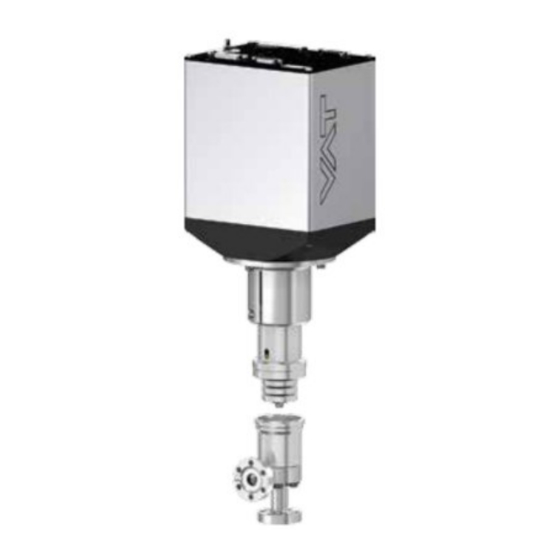
Variable leak valve DN 16 (5/8")
(preliminary)
with integrated controller
with RS232 interface
Series 590
DN 16 mm (I.D. 5/8")
This manual is valid for the following product ordering number:
59024-GEGG-AAD1
configured with firmware 612P.1E.D3
Sample picture
298292EB
Edition 2013-05-13
Advertisement
Table of Contents

Subscribe to Our Youtube Channel
Related Manuals for VAT 590 Series


Summary of Contents for VAT 590 Series
- Page 1 Installation, Operating & Maintenance Instructions Variable leak valve DN 16 (5/8") (preliminary) with integrated controller with RS232 interface Series 590 DN 16 mm (I.D. 5/8") This manual is valid for the following product ordering number: 59024-GEGG-AAD1 configured with firmware 612P.1E.D3 Sample picture 298292EB Edition 2013-05-13...
- Page 2 The VAT firmware may not be used for purposes other than those intended nor is it permitted to make copies of the VAT firmware. In particular, it is strictly forbidden to give copies of the VAT firmware to other people.
-
Page 3: Table Of Contents
Series 590 Contents Description of product ................ 5 Identification of product ....................5 Use of product ......................... 5 Used abbreviations ......................5 Related documents......................5 Important information....................... 5 Technical data ......................... 6 1.6.1 Control and actuating unit .................. 6 1.6.2 Valve unit ...................... - Page 4 Series 590 Close valve ........................39 Open valve........................39 Position control ......................40 Pressure control ......................40 Display information ......................41 5.6.1 Power up ......................41 5.6.2 Operation ......................42 5.6.3 Errors ....................... 43 5.6.4 Safety mode ..................... 43 Operation under increased temperature ................ 43 5.7.1 Bake-out ......................
-
Page 5: Description Of Product
Used abbreviations Abbreviation Description Related documents Product data sheet Dimensional drawing Important information This symbol points to a very important statement that requires particular attention. Example: VAT disclaims any liability for damages resulting from inappropriate packaging. 298292EB Edition 2013-05-13 5/56... -
Page 6: Technical Data
DESCRIPTION OF PRODUCT Series 590 Technical data 1.6.1 Control and actuating unit Description Input voltage +24 VDC (±10%) @ 0.5 V pk-pk max. [connector: POWER] Power consumption 38 W [connector: POWER] Sensor power supply output +24 VDC / 1500 mA max. [connector: SENSOR] Sensor input 0-10 VDC / Ri>100 kΩ... -
Page 7: Valve Unit
Series 590 DESCRIPTION OF PRODUCT 1.6.2 Valve unit Description ≤ Leak rate to outside 1 × 10E-10 mbar l/s ≤ Leak rate valve seat at (close position) 1 × 10E-10 mbar l/s 20’000 Cycles until first service Bake-out temperature ≤ 300°C Open / closed ≤... -
Page 8: Safety
SAFETY Series 590 Safety Compulsory reading material Read this chapter prior to performing any work with or on the product. It contains important information that is significant for your own personal safety. This chapter must have been read and understood by all persons who perform any kind of work with or on the product during any stage of its serviceable life. -
Page 9: Personnel Qualifications
Series 590 SAFETY Personnel qualifications WARNING Unqualified personnel Inappropriate handling may cause serious injury or property damage. Only qualified personnel are allowed to carry out the described work. 298292EB Edition 2013-05-13 9/56... -
Page 10: Design And Function
DESIGN AND FUNCTION Series 590 Design and Function Design open closed mechanical position indicator Figure 3-1 Function The valve plate acts as a throttling element and varies the conductance of the valve opening. Actuation is performed with a stepper motor and controller. The stepper motor/controller version ensures accurate pressure control due to exact gate positioning. -
Page 11: Installation
Make sure that the supplied products are in accordance with your order. Inspect the quality of the supplied products visually. If it does not meet your requirements, please contact VAT immediately. Store the original packaging material. It may be useful if products must be returned to VAT. -
Page 12: Installation Into The System
INSTALLATION Series 590 Installation into the system NOTICE Sealing surfaces Sealing surfaces of valve and vacuum system could be damage in case of incorrect handling. Only qualified personal are allowed to install the valve into the vacuum system. NOTICE Wrong connection Wrong connection may result in damage of controller or power supply. -
Page 13: Installation Space Condition
Series 590 INSTALLATION 4.2.1 Installation space condition Install the valve with integrated controller with space for dismantling and air circulation as shown in figure below. Figure 4-1 298292EB Edition 2013-05-13 13/56... -
Page 14: Connection Overview
INSTALLATION Series 590 4.2.2 Connection overview System: Valve Process chamber Gas inlet Controller Pressure sensor Sensor cable Cable to remote control unit (RS232) Cable to power supply Pump Controller: Figure 4-2 14/56 Edition 2013-05-13 298292EB... -
Page 15: Installation Procedure
Series 590 INSTALLATION 4.2.3 Installation procedure 1. Remove protection flanges only prior assembly into the vacuum system. 2. Install valve [1] into the vacuum system. The valve seat side is indicated by the symbol «∆» on dimensional drawing, see also Figure 4-1. Do not admit higher forces to the valve than indicated under «Admissible forces». -
Page 16: Electrical Connection
INSTALLATION Series 590 Electrical connection NOTICE Wrong connection Wrong connection may result in damage of controller or power supply. Connect all cables exactly as shown in the following descriptions and schematics. NOTICE Burned connector pins (spark) Connector pins or electronic parts could damage, if plugged and unplugged under power. -
Page 17: Sensor Supply Concepts
Series 590 INSTALLATION 4.3.1 Sensor supply concepts Concepts: External +24 VDC supplied to POWER connector is feedthrough to SENSOR connector to supply 24 VDC sensors. Refer to chapter «Power and sensor connection (+24 VDC sensors)» for schematic and correct wiring. 4.3.2 Power and sensor connection (+24 VDC sensors) 4.3.2.1... -
Page 18: Sensor Power Wiring External
INSTALLATION Series 590 Use shielded sensor cable(s). Keep cable as short as possible, but locate it away from noise sources. Connect Power supply (+24 / GND) at DB–9 male power connector and Sensors (+24V / 0V / + / -) at DB–15 female sensor connector exactly as shown in the drawing above! Connector: Use only screws with 4–40 UNC thread for fastening the connectors! 4.3.2.2... -
Page 19: Service Port Connection
The service port (connector: SERVICE) allows to connect the valve to a RS232 port of a computer. This requires a service cable and software from VAT. You can either use our freeware 'Control View', which can be downloaded from www.vatvalve.com or purchase our 'Control Performance Analyzer'. -
Page 20: Configuration With Switches For Digital Inputs
INSTALLATION Series 590 4.4.2.1 Configuration with switches for digital inputs Figure 4-5 Connect the RS232 interface connector exactly as shown in the drawing above! Use only screws with 4–40 UNC thread for fastening the DB-25 connector! 20/56 Edition 2013-05-13 298292EB... -
Page 21: Configuration With Voltage Source For Digital Inputs
Series 590 INSTALLATION 4.4.2.2 Configuration with voltage source for digital inputs Figure 4-6 Connect the RS232 interface connector exactly as shown in the drawing above! Use only screws with 4–40 UNC thread for fastening the DB-25 connector! 298292EB Edition 2013-05-13 21/56... -
Page 22: Digital Inputs
INSTALLATION Series 590 4.4.2.3 Digital inputs Function Signal type Description Priority This function will close the valve. Valve will be in interlock mode as long as function is activated. After deactivation of function it will remain effective until - OPEN valve digital input is active - converse RS232 control command have been received Digital The function is activated when optocoupler is ‘on’... -
Page 23: Initial Operation
Series 590 INSTALLATION Initial operation 4.5.1 Setup procedure To enable this valve for pressure control setup steps 1 to 6 must be performed. In case position control is required only it’s sufficient to perform steps 1 to 4. Setup step Description Turn on external +24 VDC power supply of valve (and external 15 VDC for Power up... -
Page 24: Rs232 Interface Configuration
INSTALLATION Series 590 4.5.2 RS232 Interface configuration Interface configuration must be adapted according to application needs. The factory default setting of the interface is shown in the table below. Digital input Digital input Baud rate Data bits Stop bits Parity OPEN CLOSE 9600... -
Page 25: Fixed Pi Upstream Configuration
Series 590 INSTALLATION 4.5.3 Fixed PI upstream configuration Note: Select the pressure control algorithm with s:02 command see table below. Local operation: Remote operation: (‘Control View’ or ‘Control Performance Analyzer’) Open CV or CPA Go to «Tools» > «Terminal» and send setup command s:02 according to application needs. - Page 26 INSTALLATION Series 590 a (control mode) parameter description bc not used, set 00 PI downstream control d Setpoint Ramp Time (s): 0 = 0.0, 1 = 0.5, 2 = 1.0, 3 = 1.5, 4 = 2.0, 5 = 2.5, 6 = 3.0, 7 = 3.5, 8 = 4.0,9 = 4.5, A = 5.0, B = 5.5, C = 6.0, D = 6.5, E = 7.0, F = 7.5, G = 8.0, H = 8.5, I = 9.0, J =9.5, K = 10.0 upstream control...
-
Page 27: Optimize P-Gain, I-Gain
Series 590 INSTALLATION 4.5.3.1 Optimize P-Gain, I-Gain Introduction For pressure control the parameters P-Gain and I-Gain have to be set according to the systems characteristics. The best set of parameters can be found empirically. Normally the default settings (P-Gain=0.0056; I-Gain=0.032) will result in good pressure control performance. For some applications tuning may be required to improve performance. -
Page 28: Valve Speed Adjustment
INSTALLATION Series 590 4.5.3.2 Valve speed adjustment Valve speed effects: Response time Default value is 1000. Adjustment range is from 1 to 1000. This parameter effects valve plate actuating speed. Speed adjustment is effective for PRESSURE CONTROL and POSITION CONTROL. Normally best pressure control response is achieved with max. -
Page 29: Control Commands
Series 590 INSTALLATION 4.5.5 Control commands Acknowledgement Command (within 10ms after reception of command) Control function Description R:][xxxxxx][CR][LF] [R:][CR][LF] [i:38][CR][LF] [i:38][00xxxxxx][CR][LF] data length 6 characters for writing 8 characters starting with double zero for reading xxxxxx position SETPOINT, value depends on configuration, POSITION CONTROL refer to chapter: «RS232 setup commands, RANGE CONFIGURATION»... -
Page 30: Inquiry Commands
INSTALLATION Series 590 4.5.6 Inquiry commands Acknowledgement Command (within 10ms after reception of Inquiry function command) Description [i:76][CR][LF] [i:76][xxxxxxsyyyyyyyabc][CR][LF] data length 17 characters xxxxxx position, return value depends on configuration, refer to chapter «RS232 setup commands, RANGE CONFIGURATION» for details sign, 0 for positive pressure readings, - for negative pressure readings yyyyyyy pressure, return value depends on configuration,... - Page 31 Series 590 INSTALLATION Acknowledgement Command (within 10ms after reception of command) Inquiry function Description [i:30][CR][LF] [i:30][abcdefgh][CR][LF] data length 8 characters 0 = local operation, 1 = remote operation, 2 = locked remote operation 0 = Initialization (Refer to chapter: «Behavior during power up» 1 = synchronization, 2 = POSITION CONTROL, 3 = CLOSED 4 = OPEN, 5 = PRESSURE CONTROL, 6 = HOLD , 7 = LEARN 8 = INTERLOCK (OPEN by digital input)
- Page 32 INSTALLATION Series 590 Acknowledgement Command (within 10ms after reception of Inquiry function command) Description [i:51][CR][LF] [i:51][abcdefgh][CR][LF] data length 8 characters 0 = no service required 1 = service request, it is indicated when the control unit detects that motor steps are apparently not effective. This may happen when the valve is heavily contaminated or the gate seal is heavily sticking.
- Page 33 Series 590 INSTALLATION Acknowledgement Command (within 10ms after reception of command) Inquiry function Description [i:50][CR][LF] [i:50][abc][CR][LF] data length 3 characters FATAL ERROR error code = 000 (no error) or 020 (E 20) or 022 (E 22) or 040 (E STATUS See chapter: «Trouble shooting»...
-
Page 34: Setup Commands
INSTALLATION Series 590 4.5.7 Setup commands Acknowledgement Command (within 10ms after reception of command) Setup function Description [c:01][xx][CR][LF] [c:01][CR][LF] data length: 2 characters 00 = local operation (service port) 01 = remote operation, change to local enabled 02 = locked remote operation, change to local not possible via service port ACCESS MODE This function selects the access authorization to the valve. - Page 35 Series 590 INSTALLATION Acknowledgement Command (within 10ms after reception of command) Setup function Description [s:02][abcdefgh][CR][LF] [s:02][CR][LF] [i:02][CR][LF] [i:02][abcdefgh][CR][LF] data length 8 characters Controller algorithm: 1 = fixed PI upstream control (default) Setpoint ramp time (s) (default is 0 = 0.0): 0 = 0.0, 1 = 0.5, 2 = 1.0, 3 = 1.5, 4 = 2.0, 5 = 2.5, 6 = 3.0, 7 = 3.5, 8 = 4.0 , 9 = 4.5, A = 5.0, B = 5.5, C = 6.0, D = 6.5, E = 7.0, F = 7.5, G = 8.0, H = 8.5, I = 9.0, J = 9.5, K = 10.0...
- Page 36 INSTALLATION Series 590 Acknowledgement Command (within 10ms after reception of command) Setup function Description [V:][00xxxx][CR][LF] [V:][CR][LF] [i:68][CR][LF] [i:68][0000xxxx][CR][LF] data length 6 characters starting with double zero for writing 8 characters starting with quadruple zero for reading VALVE SPEED xxxx valve speed, 1 ... 1000 (1 = min. speed, 1000 = max. speed) This command allows changing the actuating speed of the valve plate.
-
Page 37: Error Messages
Series 590 INSTALLATION 4.5.8 Error messages Description Error message Protocol Parity error [E:][000001][CR][LF] Input buffer overflow (to many characters) [E:][000002][CR][LF] Framing error (data length, number of stop bits) [E:][000003][CR][LF] Commands <CR> or <LF> missing [E:][000010][CR][LF] : missing [E:][000011][CR][LF] Invalid number of characters (between : and [CR][LF]) [E:][000012][CR][LF] [E:][000020][CR][LF] Unknown command... -
Page 38: Operation
Local operation means that the valve is operated via the service port using a computer or the Service Box 2. When using a computer, a service cable and a software from VAT are required. You can either download our freeware 'Control View' from www.vatvalve.comor purchase our 'Control Performance Analyzer'. -
Page 39: Remote Operation
Series 590 OPERATION When communication to service port is interrupted the valve will change to remote operation. So when service cable will be disconnected or software will be shut down, the valve returns automatically to remote operation. This may result in an immediate movement of the valve depending on remote control. -
Page 40: Position Control
OPERATION Series 590 Position control The valve position is directly controlled according to the position setpoint. Local operation: Remote operation: (‘Control View’, ‘Control Performance Analyzer’ or (Refer to chapter: «RS232 control commands» ‘Service Box 2‘) for details.) Select or enter position setpoint Send POSITION CONTROL Operating in position control mode can be done very easily. -
Page 41: Display Information
Series 590 OPERATION Display information There is a 4 digit display located on the 1 2 3 4 panel. It displays configuration, status and position information. For details refer to following tables. Figure 5-2 5.6.1 Power up Description Digit 1 Digit 2 Digit 3 Digit 4... -
Page 42: Operation
OPERATION Series 590 5.6.2 Operation Description / Mode Digit 1 Digit 2 Digit 3 Digit 4 PRESSURE CONTROL mode POSITION CONTROL mode Valve closed Valve open 0 . . . 100 Closed / open interlock (Valve = valve position (%, 0 = closed / 100 = open) closed / open by digital input) HOLD (position frozen) activated Safety mode established. -
Page 43: Errors
Series 590 OPERATION 5.6.3 Errors Description Digit 1 Digit 2 Digit 3 Digit 4 Error code. Refer to chapter: «Trouble shooting» for Fatal error occurred details. Table 5-3 5.6.4 Safety mode By means of an external switch (see connection diagrams chapter «Electrical connection») the motor power supply can be interrupted. -
Page 44: Behavior During Power Up
OPERATION Series 590 Behavior during power up Reaction of valve: Valve position before Valve power up configuration = closed power up: (default) Closed (isolated) Valve remains closed. Display shows alternately ‘C C’ and ‘INIT’. Synchronization will be done when first movement command is received. Valve runs to max. -
Page 45: Trouble Shooting
Series 590 OPERATION 5.10 Trouble shooting Failure Check Action - No dots lighted on display - 24 V power supply ok? - Connect valve to power supply according to chapter «Electrical connection» and make sure that power supply is working. - Remote operation does not work - Local operation via service - Switch to remote operation. - Page 46 OPERATION Series 590 Failure Check Action - Sensor(s) connected? - Refer to chapter «Electrical connection». - Pressure reading is wrong - Check valve version on page 1. Verify configuration. pressure reading is negative Refer to chapter «Setup procedure». - Does sensor power supply - Verify sensor supply voltage.
-
Page 47: Maintenance
MAINTENANCE Maintenance Maintenance may only be carried out by the VAT service staff. In exceptional cases, the customer is allowed to carry out the maintenance, but only with the prior consent of VAT. Please contact one of our service centers. You will find the addresses on our website www.vatvalve.com. -
Page 48: Repairs
Series 590 Repairs Repairs may only be carried out by the VAT service staff. In exceptional cases, the customer is allowed to carry out the repairs, but only with the prior consent of VAT. Please contact one of our service centers. You will find the addresses on our website www.vatvalve.com. -
Page 49: Dismounting And Storage
Series 590 DISMOUNTING AND STORAGE Dismounting and Storage WARNING Unqualified personnel Inappropriate handling may cause serious injury or property damage. Only qualified personnel are allowed to carry out the described work. Dismounting WARNING Harmful substances Risk of serious injury in case of contact with harmful substances. Remove harmful substances (e. -
Page 50: Storage
DISMOUNTING AND STORAGE Series 590 Storage NOTICE Wrong storage Inappropriate temperatures and humidity may cause damage to the product. Valve must be stored at: – relative humidity between 10% and 70% – temperature between +10 °C and +50 °C – non-condensing environment NOTICE Inappropriate packaging Product may get damaged if inappropriate packaging material is used. -
Page 51: Packaging And Transport
If products are radioactively contaminated, the VAT form «Contamination and Radiation Report» must be filled out. Please contact VAT in advance. If products are sent to VAT in contaminated condition, VAT will carry out the decontaminating procedure at the customer's expense. -
Page 52: Transport
Series 590 Transport NOTICE Inappropriate packaging Product may get damaged if inappropriate packaging material is used. Always use original packaging material and handle product with care. VAT disclaims any liability for damages resulting from inappropriate packaging. 52/56 Edition 2013-05-13 298292EB... -
Page 53: Disposal
Series 590 DISPOSAL Disposal WARNING Harmful substances Environmental pollution. Discard products and parts according to the local regulations. 298292EB Edition 2013-05-13 53/56... -
Page 54: Spare Parts
SPARE PARTS Series 590 Spare parts There are no spare parts defined. Please contact one of our service centers. You will find the addresses on our website www.vatvalve.com. 54/56 Edition 2013-05-13 298292EB... -
Page 55: Appendix
Series 590 APPENDIX Appendix 298292EB Edition 2013-05-13 55/56... - Page 56 Series 590 This Page Intentionally Left Blank 56/56 Edition 2013-05-13 298292EB...
Need help?
Do you have a question about the 590 Series and is the answer not in the manual?
Questions and answers