VAT 571 Series Installation, Operating, & Maintenance Instructions
All-metal angle valve with single acting pneumatic actuator and closing spring
Hide thumbs
Also See for 571 Series:
Table of Contents
Advertisement
Quick Links
Installation, Operating &
Maintenance Instructions
All-Metal Angle Valve
with single acting pneumatic actuator and closing spring
Series 571
DN 16 – 40 mm (I. D. ⅝" – 1½")
This manual is valid for the following product ordering numbers:
57124- . E . . - ....
57132- . E . . - ....
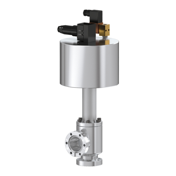
Sample picture
941265EA
Edition 2020-06-12
Advertisement
Table of Contents

Related Manuals for VAT 571 Series


Summary of Contents for VAT 571 Series
- Page 1 Installation, Operating & Maintenance Instructions All-Metal Angle Valve with single acting pneumatic actuator and closing spring Series 571 DN 16 – 40 mm (I. D. ⅝" – 1½") This manual is valid for the following product ordering numbers: 57124- . E . . - …. 57132- .
- Page 2 The VAT firmware may not be used for purposes other than those intended nor is it permitted to make copies of the VAT firmware. In particular, it is strictly forbidden to give copies of the VAT firmware to other people.
-
Page 3: Table Of Contents
Series 571 Contents Description of product ................ 4 Identification of product ....................4 Use of product ......................... 4 Related documents......................4 Important information....................... 4 Technical data ......................... 4 Safety ....................5 Compulsory reading material ................... 5 Danger levels ........................5 Personnel qualifications .................... -
Page 4: Description Of Product
Dimensional drawing Important information This symbol points to a very important statement that requires particular attention. Example: VAT disclaims any liability for damages resulting from inappropriate packaging. Technical data See product data sheet and dimensional drawing. Weights of standard valves: DN 16: 3.05 kg... -
Page 5: Safety
Series 571 SAFETY Safety Compulsory reading material Read this chapter prior to performing any work with or on the product. It contains important information that is significant for your own personal safety. This chapter must have been read and understood by all persons who perform any kind of work with or on the product during any stage of its serviceable life. -
Page 6: Safety Labels
SAFETY Series 571 Unqualified personnel Inappropriate handling may cause serious injury or property damage. Only qualified personnel are allowed to carry out the described work. Safety labels Label Part No. Location on valve T-9001-155 On protective covers of flanges Table 2-1 6/31 Edition 2020-06-12 941265EA... -
Page 7: Design And Function
Series 571 DESIGN AND FUNCTION Design and Function Design Figure 3-1 Actuator Valve body Connecting flange Sealing surface 941265EA Edition 2020-06-12 7/31... -
Page 8: Function
DESIGN AND FUNCTION Series 571 Function Valve is closed by a spring. Valve is opened pneumatically. Closing: The valve plate moves towards the seat. The VATRING (1) moves into the valve seat and closes leak tight. Opening: The valve plate moves back from the valve seat until the open stop is reached. 1 VATRING 2 Bonnet seal 3 Bellows... -
Page 9: Installation
Make sure that the supplied products are in accordance with your order. • Inspect the quality of the supplied products visually. If it does not meet your requirements, please contact VAT immediately. • Store the original packaging material. It may be useful if products must be returned to VAT. -
Page 10: Installation Into The System
INSTALLATION Series 571 Installation into the system WARNING Movable parts Human body parts may get jammed and severely injured. Do not connect or supply electrical power and compressed air before the product is completely mounted in the system. NOTICE Contamination Product may get contaminated. - Page 11 Series 571 INSTALLATION Remove plastic bag. 1 Protective covers Figure 4-1 Remove protective covers (1). Store protective covers. They may be useful when valve needs to be repacked. Clean sealing surfaces; see «Figure 3-1» on page 7, with a cleanroom wiper soaked with pure alcohol (Isopropanol).
- Page 12 INSTALLATION Series 571 4.2.2 Mounting to the system Flange A (valve seat side) Flange B Screw holes Figure 4-2 Mount valve to your system by using appropriate flange screws (different quantity of screws required – depending on valve size). Mount screws evenly in crosswise order until the seal touches the sealing surface. Tighten all screws with the torques appropriate for the property classes of the screws.
- Page 13 Series 571 INSTALLATION Leak detection port Figure 4-3 941265EA Edition 2020-06-12 13/31...
-
Page 14: Compressed Air Connection
INSTALLATION Series 571 Compressed air connection WARNING Valve in open position Risk of injury when compressed air is connected to the valve. Connect compressed air only when: – valve is installed in the vacuum system – moving parts cannot be touched NOTICE Wrong sequence of connections Valve mechanism may get damaged when electrical power is being connected before... -
Page 15: Electrical Connection
Series 571 INSTALLATION Electrical connection DANGER Electric shock Parts being under voltage will result in serious injury or death. Do not touch parts being under voltage. NOTICE Wrong sequence of connections Valve mechanism may get damaged when electrical power is being connected before compressed air is connected. -
Page 16: Operation
OPERATION Series 571 Operation WARNING Unqualified personnel Inappropriate handling may cause serious injury or property damage. Only qualified personnel are allowed to carry out the described work. WARNING Movable parts Human body parts may get jammed and severely injured. Do not operate before product is installed completely into the vacuum system. Normal operation The valve is closed by a closing spring and opened with compressed air. -
Page 17: Operation Under Increased Temperature
Series 571 OPERATION Operation under increased temperature Maximum allowed temperature, see product data sheet. NOTICE Inconstant temperatures Performance of the valve may deteriorate. – Actuate valve only after the bake-out temperature has been stable for two – hours. – If valve must be actuated during bake-out, make sure that the heating or –... -
Page 18: Behavior In Case Of Power Failure
OPERATION Series 571 Behavior in case of power failure See product data sheet. 5.5.1 Manual emergency operation WARNING Movable parts Human body parts may get jammed and severely injured. Keep human body parts away from movable parts. The solenoid valves are provided with manual emergency operation (slotted screw). This screw allows actuating the valve in case of a power failure. -
Page 19: Trouble Shooting
Position of slotted Turn slotted screw to «5.5.1 Manual emergency screw the correct position operation» Leak at gate Condition of gate seal Please contact VAT www.vatvalve.com Operating pressure Adjust operating «4.3 Compressed air pressure connection» Leak at body Condition of bonnet Please contact VAT www.vatvalve.com... -
Page 20: Maintenance
• When the valve has reached the specified lifetime; see product data sheet, we recommend having it serviced by VAT. Please contact your nearest VAT service center to get recommendations and an offer. You will find the addresses on our website www.vatvalve.com. -
Page 21: Repairs
Product may get contaminated. Always wear cleanroom gloves when handling the product. Repairs may only be carried out by the VAT service staff. In exceptional cases, the customer is allowed to carry out the repairs, but only with the prior consent of VAT. -
Page 22: Replacement Of Dynamic Seal Vatring
In case of a seat seal leak caused by environmental influences and no visible damage of the sealing surface at the seat, the VATRING seal can be replaced. VAT offers a range of components; see «Table 11-1» on page 31. The seal exchange can be carried out by the user. - Page 23 Series 571 REPAIRS Ordering information: See chapter «11 Spare parts» on page 31 and «Figure 7-1» on page 22. NOTICE Inappropriate mounting position of valve Maintenance may be troublesome, and parts may drop down. Ideally dismount valve from the system and put it on a clean workbench with the actuator upwards.
- Page 24 REPAIRS Series 571 Make sure that the seal ring is installed in the correct direction. 23. Put holding ring (62) on plate (15/1). 24. Insert screw (67) and tighten them slightly only. 25. Level out VATRING (36/1) and plate (15/1) along the whole circumference. Height difference shall not exceed 0.1 mm.
- Page 25 Series 571 REPAIRS 28. Put bonnet seal (36/2) on sealing surface of valve body. 36/2 Figure 7-4 Make sure that the seal ring is installed in the correct direction. 29. Move valve insert (in open secured position) carefully into the valve without touching the body wall.
-
Page 26: Dismounting And Storage
DISMOUNTING AND STORAGE Series 571 Dismounting and Storage WARNING Unqualified personnel Inappropriate handling may cause serious injury or property damage. Only qualified personnel are allowed to carry out the described work. WARNING Hazardous components Human body parts may get jammed and severely injured. Before dismounting the product –... -
Page 27: Dismounting
Series 571 DISMOUNTING AND STORAGE Dismounting NOTICE Valve in open position Valve mechanism may get damaged if valve is in open position. Close valve before dismounting the valve from the system. 32. Close valve. 33. Disconnect electrical power supply. 34. Disconnect compressed air supply. 35. -
Page 28: Packaging And Transport
If products are radioactively contaminated, the VAT form «Contamination and Radiation Report» must be filled out. Please contact VAT in advance. • If products are sent to VAT in contaminated condition, VAT will carry out the decontamination procedure at the customer's expense. 28/31 Edition 2020-06-12... -
Page 29: Packaging
Make sure that the valve is closed. 39. Install protective covers on all flanges. See «Figure 4-1» on page 11. 40. Pack valve appropriately, by using the original packaging material. VAT disclaims any liability for damages resulting from inappropriate packaging. Transport NOTICE Inappropriate packaging Product may get damaged if inappropriate packaging material is used. -
Page 30: Disposal
DISPOSAL Series 571 Disposal WARNING Harmful substances Environmental pollution. Discard products and parts according to the local regulations. 30/31 Edition 2020-06-12 941265EA... -
Page 31: Spare Parts
«1.1 Identification of product». This is to ensure that the appropriate spare parts are supplied. • VAT makes a difference between spare parts that may be replaced by the customer and those that need to be replaced by the VAT service staff. •...
Need help?
Do you have a question about the 571 Series and is the answer not in the manual?
Questions and answers