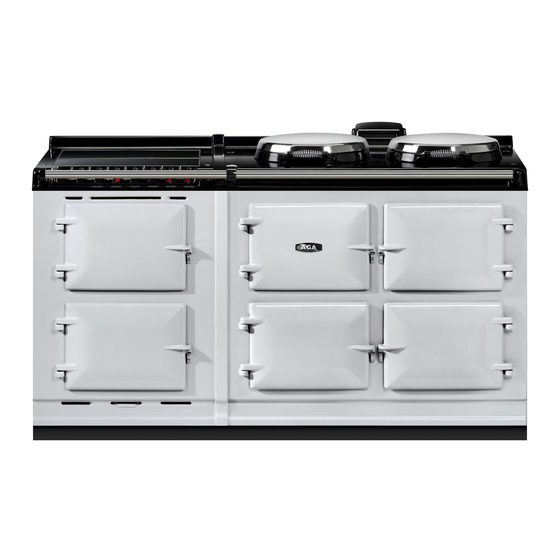
AGA 7 Series User's Manual & Installation Instructions
Integrated module with gas top burner
Hide thumbs
Also See for 7 Series:
- User's manual & installation instructions (40 pages) ,
- Manual (15 pages) ,
- Owner's manual (20 pages)
Table of Contents
Advertisement
Quick Links
AGA 7 SERIES INTEGRATED MODULE
CAUTION: THIS UNIT IS HEAVY, PROPER EQUIPMENT AND ADEQUATE MANPOWER MUST BE USED IN MOVING THE
REMEMBER, when replacing a part on this appliance, use only spare parts that you can be assured conform to the safety and
DO NOT use reconditioned or copy parts that have not been clearly authorised by AGA.
WARNING! IF THE INFORMATION IN THIS MANUAL IS NOT FOLLOWED EXACTLY, A FIRE OR EXPLOSION MAY
RESULT CAUSING PROPERTY DAMAGE, PERSONAL INJURY OR DEATH
DO NOT STORE OR USE GASOLINE OR OTHER FLAMMABLE VAPORS AND LIQUIDS IN THE VICINITY OF THIS
WHAT TO DO IF YOU SMELL GAS:
• DO NOT TRY TO LIGHT ANY APPLIANCE.
• DO NOT TOUCH ANY ELECTRICAL SWITCH;
• DO NOT USE ANY PHONE IN YOUR BUILDING.
• IMMEDIATELY CALL YOUR GAS SUPPLIER FROM A NEIGHBOR'S PHONE.
FOLLOW THE GAS SUPPLIER'S INSTRUCTIONS.
• IF YOU CANNOT REACH YOUR GAS SUPPLIER , CALL THE FIRE DEPARTMENT.
INSTALLATION AND SERVICE MUST BE PERFORMED BY A QUALIFIED INSTALLER,
WITH GAS TOP BURNERS
User Guide &
Installation Instructions
RANGE TO AVOID DAMAGE TO THE UNIT OR THE FLOOR.
performance specification that we require.
OR ANY OTHER APPLIANCE.
SERVICE AGENCY OR THE GAS SUPPLIER.
PLEASE READ THESE INSTRUCTIONS BEFORE USING THIS APPLIANCE
AND KEEP IN A SAFE PLACE FOR FUTURE REFERENCE.
For use in USA & CAN
03/23 EINS 517968
Advertisement
Table of Contents

Related Manuals for AGA 7 Series


Summary of Contents for AGA 7 Series
- Page 1 REMEMBER, when replacing a part on this appliance, use only spare parts that you can be assured conform to the safety and performance specification that we require. DO NOT use reconditioned or copy parts that have not been clearly authorised by AGA. WARNING! IF THE INFORMATION IN THIS MANUAL IS NOT FOLLOWED EXACTLY, A FIRE OR EXPLOSION MAY...
- Page 2 Make a note of your AGA 7 Series Serial Number when it is being installed. My AGA Details: Serial No: AGA Service No: Date of Installation: Data badge located behind cover...
-
Page 3: Table Of Contents
Contents Product Safety Health & Safety Installation Introduction Technical Data Installation introduction Location Installation Sequence & Procedure Chassis Installation Electrical Connections 10. Gas Connections 11. Final Fitting 12. Servicing Notes 13. Circuit Diagram 14. Servicing and warranty... -
Page 5: Product Safety
Product Safety Meaning / Description Symbol Signification / Description WARNING / CAUTION AVERTISSEMENT An appropriate safety instruction Une consigne de sécurité appropriée should be followed or caution to a doivent être suivies ou garde d’un potential hazard exists. danger potentiel exists. TENSION DANGEREUSE DANGEROUS VOLTAGE Pour indiquer les dangers... -
Page 6: Health & Safety
• Always when opening an oven door, allow hot air and • PLEASE READ THE ACCOMPANYING WARRANTY. Any steam to escape. alteration that is not approved by AGA could invalidate • Always use dry pot holders. A moist pot holder will the approval of the appliance, operation of the warranty cause steam burns. - Page 7 IMPORTANT SAFETY INSTRUCTIONS Deep Fat Frying NEVER • Use a deep pan. • Never store items of interest to children above the range. • Never fill the pan more than one-third full of fat or oil • Never allow children to climb on, sit or stand on any •...
-
Page 8: Installation Introduction
WARNING: This appliance shall be installed in The AGA 7 Series Module arrives on 1 pallet and attaches to accordance with the regulations in force and only an existing AGA 7 Series range, creating a seamless 5-oven or used in a well ventilated space. - Page 9 Specifications AGA R7/eR7 with Gas Hob Module Fig. 3.1 OVERHEAD CUPBOARD OVERHEAD CUPBOARD POSITION OF LIDS POSITION OF LIDS WHEN RAISED WHEN RAISED OVEN DOOR IN OVEN DOOR IN OPEN POSITION OPEN POSITION PLAN VIEW PLAN VIEW N*** 1598 1388...
- Page 10 AGA R7/eR7 with Hotcupboard and Gas Hob Module Fig. 3.2 OVERHEAD CUPBOARD OVERHEAD CUPBOARD FRONT VIEW POSITION OF POSITION OF LIDS WHEN LIDS WHEN RAISED RAISED LEFT_HAND SIDE VIEW HOTCUPBOARD HOTCUPBOARD ELECTRICITY SUPPLY ELECTRICITY SUPPLY PLAN VIEW OVEN DOOR IN...
-
Page 12: Technical Data
Technical Data HOTPLATE - NATURAL GAS Right-hand Front Left-hand Rear Right-hand Rear Left-hand Front Burner type ULTRA - RAPID (WOK) RAPID SEMI - RAPID SEMI - RAPID Maximum heat input 3.50 kW 3.10 kW 1.80 kW 1.80 kW Input 12,000 Btu/hr 10,600 Btu/hr 6,150 Btu/hr 6,150 Btu/hr... -
Page 13: Installation Introduction
• The data plate is situated in the centre vent slot near the AN AUTHORISED AGA ENGINEER. base of the front plate. • The AGA Module is supplied from the manufacturers in • This appliance is not connected to a combustion a fully assembled condition. -
Page 14: Location
Location Refer to Fig. 3.1 It is recommended that any soft material flooring is removed from where the Module will be installed. Any adjacent walls that project above the height of the hob must be of heat resistant material. The side wall above the hob shall be greater than 3” (76mm) from the cooker. -
Page 15: Installation Sequence & Procedure
Also check height differential between the Module plinth and AGA R7/eR7 plinth is correct: 7/16” (11 mm). If necessary, use the adjusting studs in each corner to level the plinth. In extreme instances, shims may be used underneath the plinths (See Fig. - Page 16 Fig. 7.1 Fig. 7.2 FOR AGA R7/eR7 + MODULE ONLY 11mm height differential Plinth base DESN 517427 DESN 516276 Fig. 7.3 Fig. 7.4 FOR AGA R7/eR7 with hotcupboard + MODULE ONLY 11mm height differential Hotcupboard Plinth base 16.5 mm gap...
-
Page 17: Chassis Installation
(WOK BURNER ONLY) place by tightening the two M6 screws fully. DESN 511646 15. Check to ensure that the Module front plate and AGA R7/eR7 front plate are the same height, and that the Fig. 8.3 overlap strips correspond correctly. If not, adjustment should be made to the relevant appliance, at this stage. - Page 18 Connecting To Gas Fig. 8.4 The cooker must be installed by connection to rigid pipework, which should not be less than 15 mm diameter. Pressure test nipple Connection is made to the 15 mm compression fitting 15mm compression nut located just below the hotplate level on the rear left hand side of the cooker.
-
Page 19: Electrical Connections
Check that 14-30R Fig. 9.1 Connectors on the appliance end must be the Module front plate and AGA 7 Series l front plate are provided at the point the power supply enters the appliance. - Page 20 Fig. 9.1 GREEN (GROUND) WHITE (NEUTRAL) DESN 511752 Fig. 9.2 DESN 517044...
-
Page 21: Gas Connections
Mark off appropriate position on wall for gas supply to cooker. Fig. 3.1 or Fig. 3.2 and Fig. 10.1. b. Isolate the gas supply and connect pipework as AGA Hearth Level required up to the position marked. 580 mm 60 mm c. -
Page 22: Final Fitting
11. Final Fitting Apply tape (provided) to the underside of the lap strip Fig. 11.1 on the Module top plate. Replace module hotplate. Reassemble in reverse BURNER order and reconnect the mains wire (See Electrical Connections). Ensure burner heads and burner caps are correctly located (See Fig. -
Page 23: Servicing Notes
12. Servicing Notes DISCONNECT FROM ELECTRICITY SUPPLY BEFORE C. TO CHANGE IGNITION GENERATOR SERVICING. Turn off electricity supply. WHEN RE-WIRING ANY ELECTRICAL COMPONENTS Remove top plate and hotplate (See sections A and B). REFER TO CIRCUIT DIAGRAM AND ELECTRICAL SCHEMATIC DIAGRAM ATTACHED BEFORE ELECTRICAL Remove two screws retaining the generator fixing RECONNECTION CHECK THAT THE APPLIANCE IS bracket to the burner mounting panel, and remove... - Page 24 F. TO CHANGE OVEN THERMOSTAT/GRILL CONTROL Fig. 12.1 Turn off electricity supply. Remove hotplate and top plate (see sections A and B). Remove two screws retaining the thermostat/grill control to the controls panel. Pull all of the wiring off the thermostat or grill control. The grill control can now be removed.
- Page 25 Fig. 12.4 Fig. 12.8 ADJUSTMENT FOR NATURAL GAS/PROPANE SPARK GENERATOR DESN 517976 Fig. 12.9 TERMINAL BLOCK DESN 517047 Fig. 12.5 DESN 511649 Fig. 12.6 DESN 511650 Fig. 12.7 GAS RAIL SUPPORT BRACKET SCREWS GAS RAIL TUBE NUT GAS RAIL SUPPORT BRACKET SCREWS GAS TAP TUBE NUT...
-
Page 26: Circuit Diagram
13. Circuit Diagram Fig. 13.1 CONTROL / BURNER PANEL EARTH COLOUR KEY BL - BLUE WH - WHITE IGNITION SWITCH IGNITION GENERATOR R - RED BK - BLACK Y - YELLOW PK - PINK BR - BROWN P - PURPLE GR - GREY TERMINAL GRILL... -
Page 27: Servicing And Warranty
14. Servicing and warranty • Your AGA does not need to be regularly serviced. • Fans may need periodic replacement. • In the event of requiring maintenance, please call AGA Service or your authorised distributor. • Your appliance MUST only be maintained and installed by a qualified engineer, AGA engineer or an authorised distributor. - Page 28 For further advice or information contact your local AGA Specialist With Middleby Residential policy of continuous product improvement, the Company reserves the right to change specifications and make modifications to the appliance described and illustrated at any time. Middleby Residential...
Need help?
Do you have a question about the 7 Series and is the answer not in the manual?
Questions and answers