
Related Manuals for UNIS Lane Master


Summary of Contents for UNIS Lane Master
- Page 1 IMPORTANT www.universal-space.com NOTE: Some portions of assembly may require additional assistance. Operation Manual...
- Page 2 Lane Master Manual WE ARE HERE TO ASSIST For parts and service Have Questions? Contact us! UNIS SERVICE CENTER Tel: 972-241-4263 Fax: 214-919-4918 Email: service@unisusasupportcenter.com 01/17/2018...
-
Page 3: Table Of Contents
Lane Master Manual CONTENT IMPORTANT SAFETY INSTRUCTIONS ................ 3 1. SPECIFICATIONS ..................... 5 2. CONTENTS OF THE ACCESSORY KIT ..............7 3. PART NAME ......................9 4. SET UP & INSTALLATION ..................10 5. HOW TO PLAY ......................20 6. GAME OPTION ....................... 21 7. -
Page 4: Important Safety Instructions
Lane Master Manual Thank you for purchasing Lane Master. We hope you enjoy the product. This manual contains valuable information about how to operate and maintain your game machine properly and safely. It is intended for the owner and/or personnel in charge of product operation. - Page 5 Lane Master Manual Use the following safety guidelines to help ensure your own personal safety and to help protect your equipment and surrounding environment from potential damage. This product is an indoor game machine. Do not install outdoors. Avoid installing in the following places to prevent fire, electric shock, injury and/or machine malfunctioning: ...
-
Page 6: Specifications
Lane Master Manual 1. SPECIFICATIONS Rated power supply: AC110V 50/60Hz; AC220V 50/60Hz Min. Power consumption: 520W Max. Power consumption: 580W Dimension: W65×D116×H105 in W1650×D2921×H2651 (mm) Weight:Approximately 1150 lb Part No: L105 Model No: C-489 NOTICE: After turning off the game, please wait at least 1 minute before restarting again. - Page 7 Lane Master Manual This machine will be divided into two parts during transportation. Back Cabinet: W65×D28.8×H85.7 in W1650×D720×H2148 mm Ally part: W64.34×D87.21×H40.12 in W1650×D2235×H1030 mm Note: Game specifications are subject to change without notice. 01/17/2018...
-
Page 8: Contents Of The Accessory Kit
Lane Master Manual 2. CONTENTS OF THE ACCESSORY KIT Open the package and make sure all the items are included: 1. Following accessories Part No. Code Name Picture 1 L105-801-000 25300171002 (171) 2 L105-803-000 25300172002 (171B) 3 L105-802-000 23301010020 Power cord... - Page 9 Lane Master Manual 2. Optional Parts Part No. Code Name Picture 1 L105-014-000 Bill acceptor box Assy. DBV door 2 L105-320-001 20211605A001A (With lock) 3 L105-809-001 20211605A003A DBV cabinet 4 L105-810-000 20211605A004 Door S cover 5 L105-504-000 25300171001 171A lock...
-
Page 10: Part Name
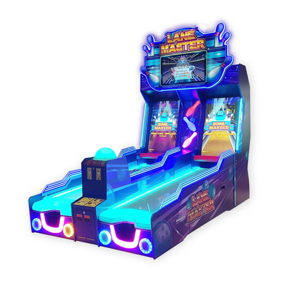
Lane Master Manual 3. PART NAME Key Components Marquee Assy. 32” display 42” LED Display Back cabinet Lane Coin Assy. Lane with coin and ticket dispenser Ticket dispenser Ball exit 01/17/2018... -
Page 11: Set Up & Installation
Lane Master Manual 4. SET UP & INSTALLATION NOTICE We do not recommend using power tools as they may cause damage. This product is an indoor game machine. Do not install outdoors. Refer to IMPORTANT SAFETY INSTRUCTIONS (Pg. 3) for places to avoid ... - Page 12 Lane Master Manual 4.3 Play Zone This machine requires space for playing and for maintenance as shown below. Leave space around the game upon installation: Service area: 20 in Service area Play area NOTICE Your unit must be leveled to operate properly.
- Page 13 Lane Master Manual 4.4 Machine Installation Before processing with assembly assure you have the following tools. Name Picture Use for Cross screwdriver For Marquee Installation& Connect Wrench Lane Assembly Connect Lane Assembly Allen hexagon wrenches & Display Assembly 4.4.1 Marquee Installation Step 1 Lift the marquee into place and Step 2 Attach support bracket.
- Page 14 Lane Master Manual Step 3 Install the bolts as indicated in the green area. Part No. Code No. Name Picture 1 L105-139-000 20104000002 Cross recessed hexagon screw 2 L105-282-000 20211605037 Fixed connected rod Cross recessed Cross recessed hexagon screw hexagon screw...
- Page 15 Lane Master Manual Connect Lane Assembly 4.4.2 Part No. Code No. Name Picture Cross recessed hexagon 1 L105-142-000 20104023002 screw Step 1 4 pcs Open the coin door and the ticket door to bolt the lanes together utilizing the hardware indicated by the red arrows.
- Page 16 Lane Master Manual 4.4.3 Connect Lane Assembly & Display Assembly Part No. Code No. Name Picture Hexagon flat round head 1 L105-125-000 20101048028 screws 2 L105-144-000 20113040051 C flat washer Place the Lane in front of the display assembly and install as shown.
- Page 17 Lane Master Manual 4.4.4 Connect Lane Assembly & Display Assembly (updated version) Place the Lane in front of the display assembly and install as shown. Step 1 Fold the right buckle to the left side. Step 2 Turn the handle clock wise to lock the latch. (Counter-clockwise to unlock the latch.) Step 3 Fold the handle after locking the latch.
- Page 18 Lane Master Manual 4.4.5 Disassemble the bowling light and Install the DBV assy. Step 1 Open the coin door and unplug two plugs. (1-Coin mech. plug; 2-Bowling light plug) Step 2 Disassemble the bowling light white plastic and light PCB 1- Check the Light PCB connector;...
- Page 19 Lane Master Manual Step 3 Install the DBV cabinet. Part No. Code No. Name Picture Cross recessed hexagon 1 L105-141-000 20104020002 screw kit Step 4 Connect the plugs. (3- DBV plugs; 4- 1P DBV plug; 5- 2P DBV plug) Step 5 Install the DBV door and your DBV.
- Page 20 Lane Master Manual Step 6 Connect the coin mech. plug. Step 7 Use the key to lock the coin door. Finish! 01/17/2018...
-
Page 21: How To Play
Lane Master Manual 5. HOW TO PLAY 5.1 Insert coins/swipe to start. 5.2 For competition, insert coin/swipe card to active each lane. 5.3 Roll the ball down the lane to hit the pins. 5.4 Enjoy your bowling experience! 5.5 Game scenes... -
Page 22: Game Option
Lane Master Manual 6. GAME OPTION 6.1 Adjustment button instruction Open the coin door and there is a meter panel. Press Settings button to get into the setting menu. Settings Test Reset 6.2 Setting menu 6.2.1 Main menu 6.2.2 Basic Setting... - Page 23 Lane Master Manual 6.2.4Input Test OFF/ON 2P Infrared1 OFF/ON 1P Coin OFF/ON 2P Infrared2 OFF/ON 1P Lane Sensor OFF/ON 2P Infrared3 OFF/ON 1P Ball Detect OFF/ON 2P Infrared4 OFF/ON 1P Ball Signal 0/100 2P Infrared5 OFF/ON 1P Ball Location 0/100...
- Page 24 Memory Minute 0-59 Display Adapter Second 0-59 Monitor Go Back & Save Screen Back Version: Lane Master V1.21 6.2.9 Bookkeeping 6.2.10 Daily Record Player1 Coins Tickets Payout Date Weekday RunTime Coins Tickets Payout 0.00 2014-06-061 Fri 00:01 0.00 Back Prev.
- Page 25 Lane Master Manual 6.3 Display Advertisement Operation In Version 1.05 or higher version for Lane Master, operator can put advertisement to the machine and display on the top monitor. Please note that the advertisement video format has to be AVI.
- Page 26 Lane Master Manual 3.Click” GameDGho” 4.Click ”Videos” 5.Copy the AVI file from memory stick into “Videos” folder. Step 3 Unplug the memory stick. Power off and restart the machine. The advertisement video will be shown on the top screen. If the video format is not AVI. It will show an error as below.
- Page 27 Lane Master Manual 6.4 Linking setting Kits for linking Part No. Name Picture Note Network L105-808-000 For two sets linking cable(5M) Swtich For three sets linking For two sets linking: Step 1 For two sets linking, please connect the network ports of two machines with Network cable(5M).
- Page 28 Lane Master Manual For three sets linking: Step 1 For three sets linking, please Step 2 For three machines linking, please For three sets linking: connect the Network cable (5M) to the connect all the network cables (5M) to the network port on the power outlet.
-
Page 29: Troubleshooting
Contact with UNIS Service. Turn on power SW again. If appeared Circuit protector make power SW again and again, machine has Power off in off state. anomaly. Please contact with UNIS Service. The connector is loose. Check connector. Card reader not working Card reader fault. - Page 30 Lane Master Manual If you see following error signs showing on the display, please try the recommended action. Display Possible Cause Recommended action Check and reconnect the The connection part of the loose ports of the PC or IO IO board and PC are loose.
- Page 31 Lane Master Manual Possible Cause Recommended action Display Loose connection of the Check and reconnect the send ball assembly. loose cables of send ball assembly. Send ball assembly Check the connection, if the broken. problem remains unresolved, please call service department for assistance.
-
Page 32: Maintenance & Inspection
Lane Master Manual 8. MAINTENANCE & INSPECTION 8.1 Safety Check Check the points listed before operating the machine. These checks are necessary for safe machine operation: 1. Test game before operation each day. 2. Conduct monthly routine checks of game components to ensure good working condition 3. - Page 33 Lane Master Manual 8.4 Disassemble the lane front plastic Loosen 4 screws on the wood board under the front plastic Screws inside Front plastic Lift up the front plastic. Unplug the plug before take out the front plastic 8.5 Display maintenance 8.5.1 Disassemble displays...
- Page 34 Lane Master Manual Metal plate 1 (3 screws) Metal plate 2&3 (2 screws) Metal plate 4 (2 screws) Note: Please hold the plastic of the display when removing metal plate 4 or it may drop down. Please reassemble display part reversed order.
-
Page 35: Overall Construction
Lane Master Manual 9. OVERALL CONSTRUCTION 9.1 General Assembly Part No. Code No. Name L105-010-000 29911605A003 Marquee Assy. L105-141-000 20104020002 Cross recessed hexagon screw kit 10 L105-001-000 29911605A001 Display Assy. L105-125-000 20101048010 Hexagon flat round head screws 16 3 L105-003-000 29911605A002 Lane Assy. - Page 36 Lane Master Manual 9.2 Display Assy. Part No. Code No. Name 1 L105-222-000 20611605028 Light bar fixed plate L105-235-000 20611605002 Light plate L105-109-000 20101010006 Hexagon flat round head screws 3 L105-002-000 29911605A004 Display Wood frame Assy. L105-296-000 26000042000A Power box assy.
- Page 37 Lane Master Manual Part No. Code No. Name L105-224-000 20611605017 Side light board 2 L105-137-000 20102040036 Cap nut L105-333-000 20211605071 Side light cover L105-334-000 20211605072 Side light cover 2 L105-126-000 20101100161 Hexagon flat round head screws Part No. Code No.
- Page 38 Lane Master Manual Part No. Code No. Name 1 L105-303-000 26000064000 U disk fixed plate 2 L105-299-000 26000055000 Dongle holder L105-440-000 20311605008 PC connected board L105-292-000 26000012000 Shake proof screw A L105-302-000 26000061000 PC power fixed bracket L105-343-000 20211605076 Video card fixed bar...
- Page 39 Lane Master Manual 9.3 Display Frame Part No. Code No. Name 1 L105-202-000 20211605001 Marquee reinforced board 2 L105-209-000 20211605042 Up mid connected plate 3 L105-206-000 20211605041 Mid connected plate 2 L105-207-000 20211605003 Rear R Lane reinforced board L105-139-000 20104000002 Cross recessed hexagon screw kit 16...
- Page 40 Lane Master Manual Part No. Code No. Name 1 L105-413-000 20311605061 Front up board 2 L105-412-000 20311605047 Top board 3 L105-411-000 20311605046 Fan board 4 L105-410-000 20311605045 Rear up board 5 L105-439-000 20311605007 Up door fixed plate 6 L105-435-000 20311605056...
- Page 41 Lane Master Manual Part No. Code No. Name 14 L105-426-000 20311605033 Lane board 15 L105-404-000 20311605001 Front bed board 16 L105-416-000 20311605003 Rear Lane bed board 2 17 L105-418-000 20311605037 Rear Lane board 18 L105-417-000 20311605031 Rear Lane back board 2...
- Page 42 Lane Master Manual Part No. Code No. Name 1 L105-432-000 20311605054 Top mid connected board 2 L105-429-000 20311605051 Up mid connected board 3 L105-430-000 20311605052 Down mid connected board 1 4 L105-402-000 20311605059 Side board 5 L105-431-000 20311605053 Bottom short connected plate 1...
- Page 43 Lane Master Manual 9.4 Lane Assy. Part No. Code No. Name 1 L105-260-000 20211605026 Sensor cover 2 L105-006-000 29911605012 L sensor Assy. L105-008-000 29911605006 Ball out system L105-118-000 20101030179 Swing screw L105-257-000 20211605025 Side light fixed plate L105-237000 20211605044 Ball out fixed plate L105-004-001 29911605A005A L Lane frame Assy.
- Page 44 Lane Master Manual Part No. Code No. Name 11 L105-288-000 20251301065 Speaker net light bracket 12 L105-005-001 29911605A006A R Lane frame Assy. 13 L105-266-000 20611605003 Bowling light cover L105-267-000 20211605029 L side plastic fixed plate L105-268-000 20211605030 R side plastic fixed plate...
- Page 45 Lane Master Manual Part No. Code No. Name L105-448-001 20311605089 Lane board L105-442-000 20311605068 Side board L105-461-000 20311605075 Up front connected board 1 L105-471-000 20311605019 Connected side board L105-462-000 20311605076 Up front cantboard L105-463-000 20311605077 Long connected board Rear connected...
- Page 46 Lane Master Manual Part No. Code No. Name L105-491-001 20311605093A Coin box top board L105-490-000 20311605092 Coin box rear board L105-492-000 20311605094 Coin box side board L105-489-000 20311605091 Coin box bed board L105-474-000 20311605020 Coin box down board L105-457-000 20311605074...
- Page 47 Lane Master Manual Part No. Code No. Name L105-478-001 20311605A005A Side board L105-480-000 20311605087 Side board L105-479-002 20311605036B Front board 01/17/2018...
- Page 48 Lane Master Manual Note: 7 &8 are alternative. Part No. Code No. Name 1 L105-324-000 20211605067 Dual meter bracket 2 L105-264-000 20211605028 Coin conduit L105-263-001 20211605027A Coin box L105-505-000 25300172001 Lock 4 L105-298-000 26000051000 Ticket cover 5 L105-304-000 26000065000 Out of ticket light cover 2...
- Page 49 Lane Master Manual 9.5 Left sensor Assy. Part No. Code No. Name L105-238-000 20211605019 Sensor fixed plate L105-135-000 20102020034 Non-metallic hexagon lock nut L105-113-000 20101020159 Cross recessed pan head screw suite 5 9.6 Right sensor Assy. Part No. Code No.
- Page 50 Lane Master Manual 9.7 Ball out Assy. Part No. Code No. Name 1 L105-249-001 20211605023A Up bowling bracket L105-250-000 20211605024 Motor shaft L105-501-000 20106130014 Diamond bearing 3 L105-255-000 20611605014 Damping board 4 L105-481-001 20311605024A Cabinet support board 5 L105-252-000 20211605051...
- Page 51 Lane Master Manual 9.8 Cabinet part Part No. Code No. Name L105-246-000 20211605048 Cantboard L105-244-000 20211605046 Side board B L105-243-000 20211605045 Side board A L105-245-000 20211605047 Bed board 9.9 Ball basket light Assy. Part No. Code No. Name 1 L105-330-001 20611605040A Bowling light cover 1...
- Page 52 Lane Master Manual 9.10 Marquee Assy. Part No. Code No. Name 1 L105-278-000 20211605034 Marquee fixed plate 2 L105-280-000 20211605035 Marquee connected rod L105-282-000 20211605037 Fixed connected rod L105-114-000 20101020186 Cross recessed hexagon screw suite 16 4 L105-281-000 20211605036 Marquee fixed bracket Part No.
- Page 53 Lane Master Manual Part No. Code No. Name L105-353-000 20611605051 Light strip pad 4 L105-158-000 20101100101 Cross recessed pan head screw 12 L105-159-000 20102030010 Hexagon flange nut L105-352-000 20611605050 Light strip pad 3 L105-158-000 20101100101 Cross recessed pan head screw 16...
- Page 54 Lane Master Manual 9.11Decals Part No. Code No. Name L105-703-000 20511605A003 L top side decal L105-704-000 20511605A004 R top side decal 2 L105-733-000 20511605A018 LOGO decal 3 L105-715-000 20511605014 Display frame decal 4 L105-739-000 20511605A023 Sensor L cover decal 5 L105-738-000 20511605A022...
- Page 55 Lane Master Manual Part No. Code No. Name 1 L105-722-000 25600000036 Warning label S 2 L105-718-000 20511605A020 Meter label 3 L105-719-000 26601100283 U disk label 4 L105-730-000 25600000096 Service label (S) L105-723-000 25600000037 Warning label L L105-729-000 25600000095 Service label (L)
- Page 56 Lane Master Manual Part No. Code No. Name 1 L105-744-000 25600000097 Network label 1 2 L105-743-000 20511605D032 Caution label 2 01/17/2018...
- Page 57 Lane Master Manual 9.12 Electrical components Part No. Code No. Name 1 L105-531-000 22002013003 LED soft light band 2 L105-522-000 21201032006 32" display assy. L105-523-000 21201042002 42" LED display L105-347-000 20641317010 Display sponge bar A L105-348-000 20641317011 Display sponge bar B L105-533-000 22002013013 5050 soft light band(Blue) 0.3...
- Page 58 Lane Master Manual Part No. Code No. Name 1 L105-554-000 23307000015 DVI-DVI cable 2 L105-554-000 23307060001 DVI-DVI cable 3 L105-568-000 23307010002 DVI-HDMI cable 4 L105-584-000 23307020001 DVI-DVI cable 5 L105-583-000 23307000018 DP-DVI cable 01/17/2018...
- Page 59 Lane Master Manual Part No. Code No. Name L105-587-000 22301000002 Coin mech. L105-538-000 22201000028 12V white light socket 2 L105-537-000 22003000018 LED light bulb 2 L105-550-000 23100000005 Ticket dispenser 3 L105-536-000 22003000003 LED light bulb(12V) 4 L105-549-000 23000000005 Meter L105-543-000 22403000001...
- Page 60 Lane Master Manual Part No. Code No. Name L105-519-100 21102000051B PC assy.(TUV) L105-519-001 21107220008 Main board L105-519-002 21107190017 L105-519-010 21107090013 Memory(4G) L105-519-004 21107060004 Hard disk L105-519-005 21107170012 Power supply L105-519-006 21107070007 CPU fan L105-519-007 21107070008 Cabinet fan L105-519-008 21107270004 PC cabinet...
- Page 61 Lane Master Manual Part No. Code No. Name 9 L105-565-000 29710826003 PCB board Short circuit board L105-559-000 29711605001 (Fuseboard01(V1.0)) Short circuit board-Fuse L105-559-001 21901000012 (Φ5*20mm T5A 250VAC) 11 L105-527-001 21602000001 Power box (UL) 12 L105-562-000 29791300001 M3 main board 13 L105-567-00023304000020...
- Page 62 Lane Master Manual AC110 Part No. Code No. Name 1 L105-544-000 22601000005 Rocket SW (S) 1 L105-517-000 21902000006 Fuse socket L105-529-000 21901000013 Fuse L105-545-000 22702000010 Fan net L105-546-000 22702010025 DC fan 4 L105-566-001 23201000001A Filter(UL) 5 L105-580-000 21412000001 Binding post...
- Page 63 Lane Master Manual WIRING DIAGRAM 01/17/2018...
- Page 64 Lane Master Manual 01/17/2018...
Need help?
Do you have a question about the Lane Master and is the answer not in the manual?
Questions and answers