Emerson Rosemount Oxymitter 4000 Instruction Manual
Oxygen
Hide thumbs
Also See for Rosemount Oxymitter 4000:
- Reference manual (198 pages) ,
- Reference manual (194 pages) ,
- Reference manual (186 pages)

Related Manuals for Emerson Rosemount Oxymitter 4000


Summary of Contents for Emerson Rosemount Oxymitter 4000
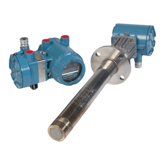
- Page 1 Instruction Manual IM-106-340, Rev 4.3 July 2017 Rosemount Oxymitter 4000 Oxygen Transmitter...
- Page 2 HIGHLIGHTS OF CHANGES Effective May 31, 2006 Rev. 4.0 Page Summary General Reformatted entire manual from a two column layout. Removed all references to JIS specifications. Replaced SPS 4000 information with SPS 4001B information. Cover Updated photo, revision number and date. viii Removed Figure 3.
- Page 3 Title page Replaced Emerson Process Management logo with Emerson logo. Replaced all instances of “Rosemount Analytical” with “Rosemount”. General Replaced all instances of “Emerson Process Management” with “Emerson”. Back cover Added URL to main website. Added social media icons and URLs.
-
Page 5: Table Of Contents
Instruction Manual IM-106-340, Rev 4.3 Oxymitter 4000 July 2017 Table of Contents Essential Instructions .................i SECTION i Preface ....................iv Definitions ....................iv Introduction Symbols ....................iv What You Need To Know ................ v Can You Use the Quick Start Guide? ............. vii Quick Start Guide for Oxymitter 4000 Systems ........ - Page 6 Instruction Manual IM-106-340, Rev 4.3 Oxymitter 4000 July 2017 Verify installation ................... 4-1 Mechanical Installation ..............4-1 SECTION 4 Terminal Block Wiring ..............4-1 Configuration of Oxymitter 4000 Configuration ............4-2 Oxymitter 4000 with LOI Logic I/O ....................4-4 Recommended Configuration ............4-6 SECTION 5 Power Up ....................
- Page 7 Instruction Manual IM-106-340, Rev 4.3 Oxymitter 4000 July 2017 Probe Replacement Parts ..............10-1 Electronics Replacement Parts ............10-6 SECTION 10 Replacement Parts SECTION 11 HART Handheld 375 Communicator ..........11-1 Asset Management Solutions (AMS) ..........11-2 Optional By-Pass Packages ................11-2 Accessories IMPS 4000 Intelligent Multiprobe Test Gas Sequencer .....
-
Page 8: Im-106-340, Rev
Instruction Manual IM-106-340, Rev 4.3 Oxymitter 4000 July 2017 TOC-4... -
Page 9: Essential Instructions
If a Model 275/375 Universal HART® Communicator is used with this unit, the software within the Model 275/375 may require modification. If a software modification is required, please contact your local Emerson Service Group or National Response Center at 1-800- 433-6076 or 1-888-433-6829. - Page 10 Instruction Manual IM-106-340, Rev. 4.3 Oxymitter 4000 July 2017...
-
Page 11: Section I
Instruction Manual IM-106-340, Rev. 4.3 Oxymitter 4000 July 2017 Section i Introduction Preface ......... page iv Definitions . -
Page 12: Preface
Instruction Manual IM-106-340, Rev. 4.3 Oxymitter 4000 July 2017 PREFACE The purpose of this manual is to provide information concerning the components, functions, installation and maintenance of the Oxymitter 4000 Oxygen Transmitter. Some sections may describe equipment not used in your configuration. The user should become thoroughly familiar with the operation of this module before operating it. -
Page 13: What You Need To Know
Highlights an operation or maintenance procedure, practice, condition, statement, etc. If not strictly observed, could result in injury, death, or long-term health hazards of personnel. BEFORE INSTALLING AND WIRING A ROSEMOUNT OXYMITTER 4000 OXYGEN TRANSMITTER 1. What type of installation does your system require? Use the following drawings, Figure 1 and Figure 2, to identify which type of installation is required for your Oxymitter 4000 system. - Page 14 Instruction Manual IM-106-340, Rev. 4.3 Oxymitter 4000 July 2017 Figure 2. Installation Options - Oxymitter 4000 with Remote Electronics OXYMITTER 4000 Line Voltage 4-20 mA Cal. Gas Instr. Air (Ref. Air) OXYMITTER 4000 WITH REMOTE ELECTRONICS AND SPS 4001B Line Voltage 4-20 mA Logic I/O Calibration Gas...
-
Page 15: Can You Use The Quick Start Guide
Instruction Manual IM-106-340, Rev. 4.3 Oxymitter 4000 July 2017 CAN YOU USE THE Use this Quick Start Guide if... QUICK START GUIDE? 1. Your system requires an Oxymitter 4000 with or without the SPS 4001B OPTION. Installation options for the Oxymitter 4000 are shown in Figure 1. -
Page 16: Quick Start Guide For Oxymitter 4000 Systems
Instruction Manual IM-106-340, Rev. 4.3 Oxymitter 4000 July 2017 QUICK START GUIDE Before using the Quick Start Guide, please read "WHAT YOU NEED TO KNOW BEFORE INSTALLING AND WIRING A ROSEMOUNT FOR OXYMITTER 4000 OXYMITTER 4000 OXYGEN TRANSMITTER" on the SYSTEMS preceding page. -
Page 17: Quick Reference Guide Manual Calibration Instructions
Instruction Manual IM-106-340, Rev. 4.3 Oxymitter 4000 July 2017 Figure 3. Oxymitter 4000 without SPS 4001B Wiring Diagram Performing a Manual Calibration with a Membrane Keypad QUICK REFERENCE GUIDE MANUAL 1. Place the control loop in manual. CALIBRATION 2. Press the CAL key. The CAL LED will light solid. INSTRUCTIONS 3. -
Page 18: Hart Communicator Fast Key Sequences
In addition to the CSC, you may also contact Field Watch. Field Watch coordinates Emerson’s field service throughout the U.S. and abroad. Phone: 1-800-654-RSMT (1-800-654-7768) Emerson may also be reached via the Internet through e-mail and the World Wide Web: e-mail: GAS.CSC@emersonprocess.com World Wide Web: www.raihome.com... -
Page 19: Component Checklist
Specifications ........page 1-16 COMPONENT A typical Rosemount Oxymitter 4000 Oxygen Transmitter should contain the items shown in Figure 1-1. Record the part number, serial number, and order... - Page 20 Instruction Manual IM-106-340, Rev. 4.3 Oxymitter 4000 July 2017 Figure 1-1. Typical System Package 1. Instruction Manual 2. IMPS 4000 Intelligent Multiprobe Test Gas Sequencer (Optional) 3. Oxymitter 4000 with Integral Electronics 4. SPS 4001B Single Probe Autocalibration Sequencer (Optional) (Shown with reference air option) 5.
-
Page 21: System Description
Instruction Manual IM-106-340, Rev. 4.3 Oxymitter 4000 July 2017 System Description The Oxymitter 4000 is designed to measure the net concentration of oxygen in an industrial combustion processes process; i.e., the oxygen remaining after all fuels have been oxidized. The probe is permanently positioned within an exhaust duct or stack and performs its task without the use of a sampling system. -
Page 22: System Configuration
Instruction Manual IM-106-340, Rev. 4.3 Oxymitter 4000 July 2017 System Configuration Oxymitter 4000 units are available in seven length options, giving the user the flexibility to use an in situ penetration appropriate to the size of the stack or duct. The options on length are 18 in. (457 mm), 3 ft (0,91 m), 6 ft (1,83 m), 9 ft (2,7 m), 12 ft (3,66 m), 15 ft (4,57 m), and 18 ft (5,49 m). - Page 23 Instruction Manual IM-106-340, Rev. 4.3 Oxymitter 4000 July 2017 Figure 1-2. Oxymitter 4000 AutoCalibration System Options 3. Membrane keypad, Figure 1-3, and HART communication are standard. To use the HART capability, you must have either: a. HART Model 275/375 Communicator. b.
- Page 24 Instruction Manual IM-106-340, Rev. 4.3 Oxymitter 4000 July 2017 Figure 1-3. Membrane Keypad HEATER T/C HEATER DIAGNOSTIC 02 CELL ALARMS CALIBRATION CALIBRATION RECOMMENDED 02 CELL mV + 02 CELL mv - TEST HEATER T/C + POINTS HEATER T/C - HIGH TEST GAS + DEC DEC PROCESS -...
- Page 25 4000. The DD software will be supplied with many Model 275/375 units but can also be programmed into existing units at most Emerson service offices. See Section 7, HART/ AMS, for additional information. ii. Personal Computer (PC) - The use of a personal computer requires AMS software available from Emerson.
-
Page 26: Handling The Oxymitter 4000
Instruction Manual IM-106-340, Rev. 4.3 Oxymitter 4000 July 2017 Figure 1-5. Model 751 LCD Display Panel 10. The optional Rosemount 751 remote-mounted LCD display panel shown in Figure 1-5 is loop-driven by the 4-20 mA output signal representing the O percentage. -
Page 27: System Considerations
Instruction Manual IM-106-340, Rev. 4.3 Oxymitter 4000 July 2017 Figure 1-7. Oxymitter 4000 HART Communications and AMS Application HART Model 275/375 4-20 mA Output Handheld (Twisted Pairs) Interface Hazardous Area Oxymitter 4000 with Integral Electronics 2 Calibration Gas Lines by Customer Termination in [300 ft (90 m) max] Control Room... - Page 28 Instruction Manual IM-106-340, Rev. 4.3 Oxymitter 4000 July 2017 Figure 1-8. Typical System Installation - Oxymitter 4000 with Integral Electronics 1-10...
- Page 29 Instruction Manual IM-106-340, Rev. 4.3 Oxymitter 4000 July 2017 Figure 1-9. Typical System Installation - Oxymitter 4000 with Remote Electronics 1-11...
-
Page 30: Imps 4000 (Optional)
Instruction Manual IM-106-340, Rev. 4.3 Oxymitter 4000 July 2017 IMPS 4000 (OPTIONAL) Information on the IMPS 4000 is available in the IMPS 4000 Intelligent Multiprobe Test Gas Sequencer Instruction Manual. SPS 4001B (OPTIONAL) The SPS 4001B Single Probe Autocalibration Sequencer provides the capability of performing automatic, timed or on demand, calibrations of a single Oxymitter 4000 without sending a technician to the installation site. -
Page 31: Model 751 Remote Powered Loop Lcd Display
Instruction Manual IM-106-340, Rev. 4.3 Oxymitter 4000 July 2017 MODEL 751 REMOTE The display (Figure 1-10) provides a simple, economical means to obtain accurate, reliable, and remote indication of important process variables. This POWERED LOOP LCD display operates on the 4-20 mA line from the Oxymitter 4000. Refer to Model DISPLAY 751 remote powered loop LCD manual for calibration and wiring. - Page 32 Instruction Manual IM-106-340, Rev. 4.3 Oxymitter 4000 July 2017 Snubber Diffusion Assembly The snubber diffusion assembly, Figure 1-12, is satisfactory for most applications. This element is also available with a flame arrestor, and with a dust seal for use with an abrasive shield. Figure 1-12.
- Page 33 Instruction Manual IM-106-340, Rev. 4.3 Oxymitter 4000 July 2017 Figure 1-14. Abrasive Shield Assembly NOTE In highly abrasive applications, rotate the shield 90 degrees at normal service intervals to present a new wear surface to the abrasive flow stream. 1-15...
-
Page 34: Specifications
Instruction Manual IM-106-340, Rev. 4.3 Oxymitter 4000 July 2017 SPECIFICATIONS Oxymitter Specifications Range Standard 0 to 10% O , 0 to 25% O , 0 to 40% O (via HART) Accuracy ±0.75% of reading or 0.05% O , whichever is greater Initial –... - Page 35 Instruction Manual IM-106-340, Rev. 4.3 Oxymitter 4000 July 2017 Oxymitter Specifications Signals Analog Output/HART 4-20 mA isolated from power supply, 950 ohms maximum load Logic I/O Two-terminal logic contact configurable as either an alarm output or as a bi-directional calibration handshake signal to IMPS 4000 or SPS 4001B, self-powered (+5 V) in series with 340 ohms Conduit ports —...
- Page 36 Instruction Manual IM-106-340, Rev. 4.3 Oxymitter 4000 July 2017 Table 1-1. Product Matrix OXT4A Oxymitter 4000 In Situ Oxygen Transmitter Oxygen Transmitter - Instruction Book Code Sensing Probe Type ANSI (N. American Std.) Probe with Ceramic Diffuser ANSI Probe with Flame Arrestor and Ceramic Diffuser ANSI Probe with Snubber Diffuser DIN (European Std.) Probe with Ceramic Diffuser DIN Probe with Flame Arrestor and Snubber Diffuser...
- Page 37 Instruction Manual IM-106-340, Rev. 4.3 Oxymitter 4000 July 2017 Cont’d Code Operator Interface HART with Membrane Keypad - blind cover HART with Membrane Keypad - window cover HART with Local Operation Interface, window cover, English only Code Language English German French Spanish Italian...
- Page 38 Instruction Manual IM-106-340, Rev. 4.3 Oxymitter 4000 July 2017 Table 1-2. Calibration Components Part Number Description 1A99119G01 Two disposable calibration gas bottles - 0.4% and 8% O , balance nitrogen - 550 liters each* 1A99119G02 Two flow regulators for calibration gas bottles 1A99119G03 Bottle rack Notes:...
-
Page 39: Verify Installation
Instruction Manual IM-106-340, Rev. 4.3 Oxymitter 4000 July 2017 Section 2 Configuration of Oxymitter 4000 with Membrane Keypad Verify Installation ....... . page 2-1 Logic I/O . -
Page 40: Oxymitter 4000 Configuration
Instruction Manual IM-106-340, Rev. 4.3 Oxymitter 4000 July 2017 Figure 2-1. Electronics Housing Terminals and Membrane Keypad Oxymitter 4000 Located on the microprocessor board, the top board, are two switches that Configuration configure outputs for the Oxymitter 4000 (Figure 2-2). SW1 determines if the 4-20 mA signal is internally or externally powered. - Page 41 Instruction Manual IM-106-340, Rev. 4.3 Oxymitter 4000 July 2017 SW2 Setting The factory sets this switch as follows: 1. Position 1 is HART/LOCAL. This switch setting controls the configura- tion of the Oxymitter 4000. The defaults cannot be changed via HART/AMS unless the switch is in the HART position.
- Page 42 Instruction Manual IM-106-340, Rev. 4.3 Oxymitter 4000 July 2017 Figure 2-2. Defaults - Oxymitter 4000 with Membrane Keypad Read O Concentration Once the cell is up to operating temperature, the O percentage can be read: 1. Access TP5 and TP6 next to the membrane keypad. Attach a multimeter across TP5 and TP6.
- Page 43 When configured as an alarm, this signal alerts you to an out-of-spec condition. The output is 5 V in series with a 340 ohm resistor. For optimum performance, Emerson recommends connecting the output to a Potter & Brumfield 3.2 mA DC relay (P/N R10S-E1Y1-J1.0K).
-
Page 44: Recommended Configuration
4-20 mA Signal Upon Critical Alarm Configuration Emerson recommends that the factory default be utilized. The 4-20 mA signal will go to the 3.5 mA level upon any critical alarm which will cause the O reading to be unusable. Customer can also select 21.6 mA as the failure setting if normal operations cause O... - Page 45 Instruction Manual IM-106-340, Rev. 4.3 Oxymitter 4000 July 2017 Section 3 Installation Mechanical Installation ......page 3-2 Electrical Installation (with Integral Electronics) .
-
Page 46: Mechanical Installation
Instruction Manual IM-106-340, Rev. 4.3 Oxymitter 4000 July 2017 MECHANICAL INSTALLATION Selecting Location 1. The location of the Oxymitter 4000 in the stack or flue is most important for maximum accuracy in the oxygen analyzing process. The Oxymitter 4000 must be positioned so the gas it measures is representative of the process. - Page 47 Instruction Manual IM-106-340, Rev. 4.3 Oxymitter 4000 July 2017 Figure 3-1. Oxymitter 4000 Probe Installation...
- Page 48 Instruction Manual IM-106-340, Rev. 4.3 Oxymitter 4000 July 2017 Figure 3-2. Oxymitter 4000 Remote Electronics Installation REMOTE ELECTRONICS REMOTE ELECTRONICS WITH MEMBRANE KEYPAD AND BLIND COVER WITH LOI AND WINDOW COVER 2.44 (62,0) DIA. 2.21 (56,0) 6.48 7.47 (164,6) (189,8) 3.33 8.72 (221,5) (84,6)
- Page 49 Instruction Manual IM-106-340, Rev. 4.3 Oxymitter 4000 July 2017 Figure 3-3. Oxymitter 4000 with Abrasive Shield...
- Page 50 Instruction Manual IM-106-340, Rev. 4.3 Oxymitter 4000 July 2017 Figure 3-4. Oxymitter 4000 Adapter Plate Dimensions...
- Page 51 Instruction Manual IM-106-340, Rev. 4.3 Oxymitter 4000 July 2017 Figure 3-5. Oxymitter 4000 Adapter Plate Installation...
- Page 52 Instruction Manual IM-106-340, Rev. 4.3 Oxymitter 4000 July 2017 Figure 3-6. Oxymitter 4000 Abrasive Shield Bracing Installation 5. In vertical installations, ensure the system cable drops vertically from the Oxymitter 4000 and the conduit is routed below the level of the electronics housing.
-
Page 53: Remote Electronics Installation
Instruction Manual IM-106-340, Rev. 4.3 Oxymitter 4000 July 2017 Figure 3-7. Orienting the Optional Vee Deflector Uninsulated stacks or ducts may cause ambient temperatures around the electronics to exceed 185°F (85°C), which may cause overheating da mage to the electronics. 8. -
Page 54: Electrical Installation (With Integral Electronics)
Instruction Manual IM-106-340, Rev. 4.3 Oxymitter 4000 July 2017 Figure 3-8. Installation with Drip Loop and Insulation Removal ELECTRICAL For Oxymitter 4000 with Integral Electronics INSTALLATION (WITH All wiring must conform to local and national codes. INTEGRAL ELECTRONICS) Disconnect and lock out power before connecting the power supply. Install all protective covers and safety ground leads after installation. - Page 55 Instruction Manual IM-106-340, Rev. 4.3 Oxymitter 4000 July 2017 NOTE To maintain proper earth grounding, ensure a positive connection exists between the sensor housing, the electronics housing, and earth. The connecting ground wire must be 14 AWG minimum. Refer to Figure 3-9. NOTE Line voltage, signal, and relay wiring must be rated for at least 221°F (105°C).
- Page 56 Instruction Manual IM-106-340, Rev. 4.3 Oxymitter 4000 July 2017 Figure 3-9. Electrical Installation - Oxymitter 4000 with Integral Electronics 3-12...
-
Page 57: Electrical Installation (With Remote Electronics)
Instruction Manual IM-106-340, Rev. 4.3 Oxymitter 4000 July 2017 ELECTRICAL For Oxymitter 4000 with Remote Electronics INSTALLATION (WITH All wiring must conform to local and national codes. REMOTE ELECTRONICS) Disconnect and lock out power before connecting the power supply. Install all protective covers and safety ground leads after installation. Failure to install covers and ground leads could result in serious injury or death. - Page 58 Instruction Manual IM-106-340, Rev. 4.3 Oxymitter 4000 July 2017 b. Calibration Handshake/Logic I/O. The output can either be an alarm or provide the handshaking to interface with an IMPS 4000 or SPS 4001B. For more information, refer to "Logic I/O" in Section 4: Configuration of Oxymitter 4000 with LOI, and either the IMPS 4000 Intelligent Multiprobe Test Gas Sequencer Instruction Manual or the SPS 4001B Single Probe Autocalibration Sequencer Instruction...
- Page 59 Instruction Manual IM-106-340, Rev. 4.3 Oxymitter 4000 July 2017 Figure 3-10. Electrical Installation - Oxymitter 4000 with Remote Electronics 3-15...
-
Page 60: Install Interconnecting Cable
Instruction Manual IM-106-340, Rev. 4.3 Oxymitter 4000 July 2017 Install Interconnecting NOTE If interconnect cable was not purchased with the Oxymitter 4000, consult the Cable factory for the proper wire type and gauge. 1. Remove cover (27, Figure 9-4) from junction box (5). Connect the electronics end of the interconnecting cable (9) to the "FROM PROBE"... - Page 61 Instruction Manual IM-106-340, Rev. 4.3 Oxymitter 4000 July 2017 Figure 3-11. Air Set, Plant Air Connection Figure 3-12. Oxymitter 4000 Gas Connections Calibration Gas Connections 3-17...
-
Page 62: Imps 4000 Connections
Instruction Manual IM-106-340, Rev. 4.3 Oxymitter 4000 July 2017 IMPS 4000 See the IMPS 4000 Intelligent Multiprobe Sequencer Instruction Manual for wiring and pneumatic connection. CONNECTIONS SPS 4001B See the SPS 4001B Single Probe Autocalibration Sequencer Instruction Manual for wiring and pneumatic connection. CONNECTIONS NOTE: Upon completing installation, make sure that the Oxymitter 4000 is turned on... -
Page 63: Verify Installation
Instruction Manual IM-106-340, Rev. 4.3 Oxymitter 4000 July 2017 Section 4 Configuration of Oxymitter 4000 with LOI Verify installation ....... . page 4-1 Logic I/O . -
Page 64: Oxymitter 4000 Configuration
Instruction Manual IM-106-340, Rev. 4.3 Oxymitter 4000 July 2017 Figure 4-1. Electronics Housing Terminals with LOI Oxymitter 4000 Located on the microprocessor board are two switches that configure outputs (Figure 4-2). To access these switches, the LOI module must be removed. Configuration SW1 determines if the 4-20 mA signal is internally or externally powered. - Page 65 Instruction Manual IM-106-340, Rev. 4.3 Oxymitter 4000 July 2017 SW2 Setting The factory sets this switch as follows: 1. Position 1 is HART/LOCAL. This switch setting controls the configura- tion of the Oxymitter 4000. The defaults cannot be changed via HART/AMS or the LOI unless the switch is in the HART position.
-
Page 66: Logic I/O
When configured as an alarm, this signal alerts you to an out-of-spec condition. The output is +5 Vdc in series with a 340 ohm resistor. For optimum performance, Emerson recommends connecting the output to a Potter & Brumfield 3.2 mA DC relay (P/N R10S-E1Y1-J1.0K). - Page 67 Instruction Manual IM-106-340, Rev. 4.3 Oxymitter 4000 July 2017 Of the ten modes in Table 4-1, mode 1 through mode 7 are the alarm modes. The factory default is mode 5 for Oxymitter 4000 units without an IMPS 4000 or SPS 4001B. In this mode, the output will signal when a unit alarm or a CALIBRATION RECOMMENDED indication occurs.
-
Page 68: Recommended Configuration
It is very important that the control system be configured to recognize these various signal levels, and operators be briefed as to their meaning. Calibration Emerson recommends utilizing an autocalibration system, actuated by the "calibration recommended" diagnostic. New O cells may operate for more than a year, but older cells may require recalibration every few weeks as they near the end of their life. -
Page 69: Power Up
Instruction Manual IM-106-340, Rev. 4.3 Oxymitter 4000 July 2017 Section 5 Startup and Operation of Oxymitter 4000 with Membrane Keypad Power Up ........page 5-1 Operation . -
Page 70: Operation
Instruction Manual IM-106-340, Rev. 4.3 Oxymitter 4000 July 2017 Error If there is an error condition at startup, one of the diagnostics LEDs will be blinking. Refer to Section 8: Troubleshooting, to determine the cause of the error. Clear the error, cycle power, and the operating display should return. Keypad The five membrane keys on the membrane keypad are only used during calibration to adjust the high and low gas and to initiate the calibration... - Page 71 Instruction Manual IM-106-340, Rev. 4.3 Oxymitter 4000 July 2017 Figure 5-2. Calibration Keys Keys INC and DEC. The INC and DEC keys are used to set the values of the calibration gases. Attach a multimeter across TP5 and TP6. The calibration and process gases can now be monitored.
- Page 72 Instruction Manual IM-106-340, Rev. 4.3 Oxymitter 4000 July 2017...
-
Page 73: Power Up
Instruction Manual IM-106-340, Rev. 4.3 Oxymitter 4000 July 2017 Section 6 Startup and Operation of Oxymitter 4000 with LOI Power Up ........page 6-1 Start Up Oxymitter 4000 Calibration . - Page 74 Instruction Manual IM-106-340, Rev. 4.3 Oxymitter 4000 July 2017 Figure 6-1. Startup Display Figure 6-2. O Concentration Display...
-
Page 75: Start Up Oxymitter 4000 Calibration
Instruction Manual IM-106-340, Rev. 4.3 Oxymitter 4000 July 2017 Figure 6-3. LOI Features Refer to Section 9: Maintenance and Service, for calibration instructions. START UP OXYMITTER 4000 CALIBRATION NAVIGATING THE LOCAL OPERATOR INTERFACE Overview The Local Operator Interface (LOI), shown in Figure 6-3, utilizes a bright blue gas-fluorescent display. -
Page 76: Loi Key Designations
Instruction Manual IM-106-340, Rev. 4.3 Oxymitter 4000 July 2017 In order to unlock the display, input a "Z" pattern. First, push the top left (gray) arrow, then the top right, followed by the bottom left and finally the bottom right. The "LK" notation in the upper right corner of the display will now dis- appear. - Page 77 Instruction Manual IM-106-340, Rev. 4.3 Oxymitter 4000 July 2017 Figure 6-4. Menu Tree for Local Operator Interface on the Oxymitter 4000 (Sheet 1 of 2)
-
Page 78: Oxymitter 4000 Setup At The Loi
Instruction Manual IM-106-340, Rev. 4.3 Oxymitter 4000 July 2017 Figure 6-4. Menu Tree for Local Operator Interface (LOI) on the Oxymitter 4000 (Sheet 2 of 2) O2 Gas 1 O2 Gas 2 (CONTINUED FROM O2-Reset Vals Yes/No SHEET 1) O2 Out Tracks Yes/No Calib Setup O2 Cal Intervl... - Page 79 IM-106-340, Rev. 4.3 Oxymitter 4000 July 2017 NOTE Emerson recommends 0.4% O and 8% O for calibration gases. O2 Reset Values - Resets factory default values. O2 Output Tracks - 4 to 20 mA signal can be held at the last value during calibration, or the signal can be left to track the cal gases.
- Page 80 Instruction Manual IM-106-340, Rev. 4.3 Oxymitter 4000 July 2017 SYSTEM/Parameters O2 Slope - O slope is data regarding the strength of the sensing cell output. This information is automatically calculated after a calibration, and the user does not normally input this data. O2 Constant - O constant is the amount of voltage a cell generates with ambient air as the calibration gas.
-
Page 81: Loi Installation
Instruction Manual IM-106-340, Rev. 4.3 Oxymitter 4000 July 2017 Temperatures O2 Temp - Indicates the thermocouple temperature at the sensing cell; this should always be 1357°F (736°C). O2 Temp Max - Maximum temperature the cell has seen. (Some process temperatures can exceed the 1357°F (736°C) setpoint temperature, and this will indicate this condition.) Board Temp - The temperature inside the Oxymitter electronics housing 185°F (85°C), is the max. -
Page 82: Oxymitter 4000 Test Points
Instruction Manual IM-106-340, Rev. 4.3 Oxymitter 4000 July 2017 OXYMITTER 4000 TEST Refer to Figure 6-6. System test points are located on the board below the LOI module. Test points 1 through 6 allow you to monitor with a multimeter: POINTS the heater thermocouple, the O cell millivolt, and the process O... -
Page 83: Overview
Instruction Manual IM-106-340, Rev. 4.3 Oxymitter 4000 July 2017 Section 7 HART/AMS Overview ........page 7-1 HART Communicator Signal Line Connections . -
Page 84: Hart Communicator Signal Line Connections
Instruction Manual IM-106-340, Rev. 4.3 Oxymitter 4000 July 2017 HART COMMUNICATOR The HART Communicator can connect to the Oxymitter 4000's analog output signal line at any wiring termination in the 4-20 mA current loop. There are SIGNAL LINE two methods of connecting the HART Communicator to the signal line. For CONNECTIONS applications in which the signal line has a load resistance of 250 ohms or more, refer to method 1. - Page 85 Instruction Manual IM-106-340, Rev. 4.3 Oxymitter 4000 July 2017 Figure 7-1. Signal Line Connections, 250 Ohms Load Resistance HART Communicator Figure 7-2. Signal Line Connections, <250 Ohms Load Resistance...
-
Page 86: Off-Line And On-Line Operations
Instruction Manual IM-106-340, Rev. 4.3 Oxymitter 4000 July 2017 OFF-LINE AND ON-LINE The HART Communicator can be operated both off-line and on-line. OPERATIONS Off-line operations are those in which the communicator is not connected to the Oxymitter 4000. Off-line operations can include interfacing the HART Communicator with a PC (refer to applicable HART documentation regarding HART/PC applications. - Page 87 Instruction Manual IM-106-340, Rev. 4.3 Oxymitter 4000 July 2017 Figure 7-3. HART/AMS Menu Tree (Sheet 1 of 3)
- Page 88 Instruction Manual IM-106-340, Rev. 4.3 Oxymitter 4000 July 2017 Figure 7-3. HART/AMS Menu Tree (Sheet 2 of 3)
- Page 89 Instruction Manual IM-106-340, Rev. 4.3 Oxymitter 4000 July 2017 Figure 7-3. HART/AMS Menu Tree (Sheet 3 of 3)
-
Page 90: Hart Communicator O
Instruction Manual IM-106-340, Rev. 4.3 Oxymitter 4000 July 2017 HART COMMUNICATOR Use the following procedure to perform a calibration using the HART Commu- nicator. If necessary, use the menu tree in Figure 7-3 (sheet 1 of 3) for CAL METHOD reference. -
Page 91: Defining A Timed Calibration Via Hart
Instruction Manual IM-106-340, Rev. 4.3 Oxymitter 4000 July 2017 11. When the "Loop should be returned to automatic control" message appears, return the Hazardous Area Oxymitter 4000 to the automatic control loops previously removed and press OK. 12. At the STOP GAS status prompt, select menu item 2, NEXT CAL STEP When the status displays PURGING, select menu item 4, EXIT, to leave the O2 CAL procedure. - Page 92 Instruction Manual IM-106-340, Rev. 4.3 Oxymitter 4000 July 2017 7-10...
-
Page 93: Overview
Instruction Manual IM-106-340, Rev. 4.3 Oxymitter 4000 July 2017 Section 8 Troubleshooting Overview ........page 8-1 General . - Page 94 Instruction Manual IM-106-340, Rev. 4.3 Oxymitter 4000 July 2017 Figure 8-1. O Sensor mV Reading vs. % O at 1357°F (736°C) (Reference Air, 20.9% EMF(mV) 7.25 16.1 18.4 21.1 23.8 27.2 31.2 36.0 0.01 EMF(mV) 42.3 51.1 66.1 71.0 77.5 81.5 86.3 101.4...
-
Page 95: General
Instruction Manual IM-106-340, Rev. 4.3 Oxymitter 4000 July 2017 Install all protective equipment covers and safety ground leads after troubleshooting. Failure to install covers and ground leads could result in serious injury or death. GENERAL The troubleshooting section describes how to identify and isolate faults that may develop in the Oxymitter 4000. -
Page 96: Alarm Contacts
Instruction Manual IM-106-340, Rev. 4.3 Oxymitter 4000 July 2017 NOTE Make sure that the Control System is configured to interpret these signal levels correctly! Once an alarm condition is indentified, the Oxymitter 4000 electronics offers a number of diagnostics to interpret the specific alarm. If the Oxymitter 4000 has the simple keypad operator interface, the majority of fault conditions will be indicated by one of the four LEDs referred to as diagnostic, or unit alarms on the operator's keypad (Figure 8-2). -
Page 97: Identifying And Correcting Alarm Indications
Instruction Manual IM-106-340, Rev. 4.3 Oxymitter 4000 July 2017 A Potter & Brumfield R10S-E1Y1-J1.0K 3.2 mA DC or an equal interposing relay will be mounted where the contact wires terminate in the control/relay room. If autocalibration systems are utilized, the bidirectional logic contact is utilized as a "hand-shake"... - Page 98 Instruction Manual IM-106-340, Rev. 4.3 Oxymitter 4000 July 2017 Table 8-1. Diagnostic/Unit Alarm Fault Definitions - Membrane Keypad Only Flashes Status 4-20 mA Line Fault Recoverable HEATER T/C Open 3.5 mA (factory default)* Shorted 3.5 mA (factory default)* Reversed 3.5 mA (factory default)* A/D Comm Error 3.5 mA (factory default)* HEATER...
- Page 99 Instruction Manual IM-106-340, Rev. 4.3 Oxymitter 4000 July 2017 Figure 8-3. Fault 1, Open Thermocouple Fault 1, Open Thermocouple Figure 8-3 shows the electronic assembly for an Oxymitter 4000 with a membrane keypad (upper view) and a Oxymitter 4000 with an LOI (lower view).
- Page 100 Instruction Manual IM-106-340, Rev. 4.3 Oxymitter 4000 July 2017 Figure 8-4. Fault 2, Shorted Thermocouple Fault 2, Shorted Thermocouple Figure 8-4 shows the electronic assembly for an Oxymitter 4000 with a membrane keypad (upper view) and an Oxymitter 4000 with an LOI (lower view).
- Page 101 Instruction Manual IM-106-340, Rev. 4.3 Oxymitter 4000 July 2017 Figure 8-5. Fault 3, Reversed Thermocouple Fault 3, Reversed Thermocouple Wiring or Faulty PC Board Figure 8-5 shows the electronic assembly for an Oxymitter 4000 with a membrane keypad (upper view) and an Oxymitter 4000 with an LOI (lower view).
- Page 102 Instruction Manual IM-106-340, Rev. 4.3 Oxymitter 4000 July 2017 Figure 8-6. Fault 4, A/D Comm Error Fault 4, A/D Comm Error Membrane Keypad When Fault 4 is detected, the HEATER T/C LED flashes four times, pauses for three seconds, and repeats (Figure 8-6). HEATER DIAGNOSTIC 1.
- Page 103 Instruction Manual IM-106-340, Rev. 4.3 Oxymitter 4000 July 2017 Figure 8-7. Fault 5, Open Heater Fault 5, Open Heater Figure 8-7 shows the electronic assembly for an Oxymitter 4000 with a membrane keypad (upper view) and a Oxymitter 4000 with an LOI (lower view).
- Page 104 Instruction Manual IM-106-340, Rev. 4.3 Oxymitter 4000 July 2017 Figure 8-8. Fault 6, High High Heater Temp Fault 6, High High Heater Temp Figure 8-8 shows the electronic assembly for an Oxymitter 4000 with a membrane keypad (upper view) and an Oxymitter 4000 with an LOI (lower view).
- Page 105 Instruction Manual IM-106-340, Rev. 4.3 Oxymitter 4000 July 2017 Figure 8-9. Fault 7, High Case Temp Fault 7, High Case Temp Figure 8-9 shows the electronic assembly for an Oxymitter 4000 with a membrane keypad (upper view) and an Oxymitter 4000 with an LOI (lower view).
- Page 106 Instruction Manual IM-106-340, Rev. 4.3 Oxymitter 4000 July 2017 Figure 8-10. Fault 8, Low Heater Temp Fault 8, Low Heater Temp Figure 8-10 shows the electronic assembly for an Oxymitter 4000 with a membrane keypad (upper view) and an Oxymitter 4000 with an LOI (lower view).
- Page 107 Instruction Manual IM-106-340, Rev. 4.3 Oxymitter 4000 July 2017 Figure 8-11. Fault 9, High Heater Temp Fault 9, High Heater Temp Figure 8-11 shows the electronic assembly for an Oxymitter 4000 with a membrane keypad (upper view) and an Oxymitter 4000 with an LOI (lower view).
- Page 108 Instruction Manual IM-106-340, Rev. 4.3 Oxymitter 4000 July 2017 Figure 8-12. Fault 10, High Cell mV Fault 10, High Cell mV Figure 8-12 shows the electronic assembly for an Oxymitter 4000 with a membrane keypad (upper view) and an Oxymitter 4000 with an LOI (lower view).
- Page 109 Instruction Manual IM-106-340, Rev. 4.3 Oxymitter 4000 July 2017 Figure 8-13. Fault 11, Bad Cell Fault 11, Bad Cell Figure 8-13 shows the electronic assembly for an Oxymitter 4000 with a membrane keypad (upper view) and an Oxymitter 4000 with an LOI (lower view).
- Page 110 Instruction Manual IM-106-340, Rev. 4.3 Oxymitter 4000 July 2017 Figure 8-14. Fault 12, EEprom Corrupt Fault 12, EEprom Corrupt Figure 8-14 shows the electronic assembly for an Oxymitter 4000 with a membrane keypad (upper view) and an Oxymitter 4000 with an LOI (lower view).
- Page 111 Instruction Manual IM-106-340, Rev. 4.3 Oxymitter 4000 July 2017 Figure 8-15. Fault 13, Invalid Slope Fault 13, Invalid Slope Figure 8-15 shows the electronic assembly for an Oxymitter 4000 with a membrane keypad (upper view) and an Oxymitter 4000 with an LOI (lower view).
- Page 112 Instruction Manual IM-106-340, Rev. 4.3 Oxymitter 4000 July 2017 Figure 8-16. Fault 14, Invalid Constan Fault 14, Invalid Constant Figure 8-16 shows the electronic assembly for an Oxymitter 4000 with a membrane keypad (upper view) and an Oxymitter 4000 with an LOI (lower view).
- Page 113 Instruction Manual IM-106-340, Rev. 4.3 Oxymitter 4000 July 2017 Figure 8-17. Fault 15, Last Calibration Failed Fault 15, Last Calibration Failed Figure 8-17 shows the electronic assembly for an Oxymitter 4000 with a membrane keypad (upper view) and an Oxymitter 4000 with an LOI (lower view).
-
Page 114: Heater Not Open, But Unable To Reach 736°C Setpoint
Instruction Manual IM-106-340, Rev. 4.3 Oxymitter 4000 July 2017 HEATER NOT OPEN, The temerature setpoint of 736°C can not be reached because the Oxymitter 5000 has an "autotune" function for establishing heater control parameters. BUT UNABLE TO REACH Probes mounted into processes that operate at above 600°C may have a 736°C SETPOINT hard time controlling the temperature with the "autotune"... - Page 115 Instruction Manual IM-106-340, Rev. 4.3 Oxymitter 4000 July 2017 2. The sensing cell is bolted to the end of the probe and uses a corrugated metallic seal (5, Figure 9-3) to separate the process gases from the ambient reference air. This seal can be used only one time so always replace this seal when a cell is removed or replaced.
- Page 116 Instruction Manual IM-106-340, Rev. 4.3 Oxymitter 4000 July 2017 Calibration Record Rosemount In Situ O Probe Probe Serial Number: Probe Tag Number: Probe Location: Date Placed Into Service: _ Date Slope Constant Impedance Response Response initial final Notes: Response When the second calibration gas is turned off, note the number of seconds required for the O value to begin migrating initial back to the process value.
-
Page 117: Overview
Instruction Manual IM-106-340, Rev. 4.3 Oxymitter 4000 July 2017 Section 9 Maintenance and Service Overview ........page 9-1 Calibration with Keypad . -
Page 118: Automatic Calibration
Instruction Manual IM-106-340, Rev. 4.3 Oxymitter 4000 July 2017 Figure 9-1. Membrane Keypad calibration gas flowmeter to 5 scfh and calibrate the Oxymitter 4000. To change the diffusion element, refer to "Ceramic Diffusion Element Replacement". Three types of calibration methods are available: automatic, semi-automatic, and manual. -
Page 119: Semi-Automatic Calibration
Instruction Manual IM-106-340, Rev. 4.3 Oxymitter 4000 July 2017 3. If using an IMPS 4000, enter a time interval via the IMPS 4000 keypad that will initiate an automatic calibration at a scheduled time interval (in hours). To set the CalIntvX parameter of the CHANGE PRESETS display mode, refer to the IMPS 4000 Intelligent Multiprobe Test Gas Sequencer Instruction Manual for more information. - Page 120 Instruction Manual IM-106-340, Rev. 4.3 Oxymitter 4000 July 2017 Figure 9-2. Inside Right Cover 2. Verify the calibration gas parameters are correct per "Calibration with Keypad". 3. If performing a manual calibration with the CALIBRATION RECOMMENDED LED off and the CAL LED off, start at step a. 4.
-
Page 121: Calibration With Loi
Instruction Manual IM-106-340, Rev. 4.3 Oxymitter 4000 July 2017 e. Remove the first calibration gas and apply the second calibration gas. (Electronics will abort the calibration if step f is not done within 30 minutes). f. Push the CAL key; the CAL LED will be on solid. The timer is activated for the second calibration gas flow. - Page 122 Instruction Manual IM-106-340, Rev. 4.3 Oxymitter 4000 July 2017 The display counts down the seconds remaining to flow Gas 1, then the time remaining for sensing the O concentration of Gas 1. Done Gas 1 indicates completion. 3. Remove the first calibration gas and apply the second calibration gas. (Electronics will abort the calibration if this step is not done within 30 minutes).
-
Page 123: Oxymitter 4000 Repair
Instruction Manual IM-106-340, Rev. 4.3 Oxymitter 4000 July 2017 OXYMITTER 4000 Each of the following procedures details how to remove and replace a specific component of the Oxymitter 4000. REPAIR It is recommended that the Oxymitter 4000 be removed from the stack for all service activities. - Page 124 Instruction Manual IM-106-340, Rev. 4.3 Oxymitter 4000 July 2017 Figure 9-3. Oxymitter 4000 with Integral Electronics - Exploded View...
- Page 125 Instruction Manual IM-106-340, Rev. 4.3 Oxymitter 4000 July 2017 Figure 9-4. Oxymitter 4000 with Remote Electronics - Exploded View REMOTE 23 25 ELECTRONICS 18 19 Note: The electronic assembly, item 12, consists of items 13 through 20. PROBE HEAD INTERCONNECTING CABLE Mounting Kit Screw...
- Page 126 Instruction Manual IM-106-340, Rev. 4.3 Oxymitter 4000 July 2017 Replace Entire Integral Electronics (with Housing) NOTE Only perform this procedure on units with integral electronics. NOTE Recalibration is required whenever electronic cards or sensing cell is replaced. 1. Follow the instructions in "Removal and Replacement of Probe", to remove the Oxymitter 4000 from the stack or duct.
- Page 127 Instruction Manual IM-106-340, Rev. 4.3 Oxymitter 4000 July 2017 Figure 9-5. Electronic Assembly Figure 9-6. J8 Connector Power Supply Board 9-11...
- Page 128 Instruction Manual IM-106-340, Rev. 4.3 Oxymitter 4000 July 2017 Electronic Assembly Replacement (Figure 9-5) 1. Remove the right housing cover uncovering the electronic assembly. 2. Depress and remove the J1 (cell and T/C) connector from the J1 socket. Loosen the three captive mounting screws (16, Figure 9-3 or Figure 9-4) on the microprocessor board (top board).
- Page 129 Instruction Manual IM-106-340, Rev. 4.3 Oxymitter 4000 July 2017 Figure 9-7. Fuse Location 6. Turn the electronic assembly over so that you are looking at the bottom of the power supply printed circuit board. Gently depress the two white posts one at a time. Carefully separate the power supply board (20) from the microprocessor board (17).
- Page 130 Instruction Manual IM-106-340, Rev. 4.3 Oxymitter 4000 July 2017 Heater Strut Replacement This paragraph covers heater strut replacement. Do not attempt to replace the heater strut until all other possibilities for poor performance have been considered. If heater strut replacement is needed, order a replacement heater strut (Table 10-1).
- Page 131 Instruction Manual IM-106-340, Rev. 4.3 Oxymitter 4000 July 2017 Figure 9-8. Heater Strut Assembly 13. For units with remote electronics, install the probe head as follows: a. See Figure 9-9. Make sure that the O-ring is in good condition. Seat the O-ring in the mating groove of the probe.
- Page 132 Instruction Manual IM-106-340, Rev. 4.3 Oxymitter 4000 July 2017 Figure 9-9. Probe to Probe Head Assembly - Remote Electronics Only Cell Replacement This paragraph covers oxygen sensing cell replacement. Do not attempt to replace the cell until all other possibilities for poor performance have been considered.
- Page 133 Instruction Manual Closed end Figure 9-10. Cell Replacement Kitl Connector IM-106-340, Rev. 4.3 Oxymitter 4000 July 2017 Use heat-resistant gloves and clothing when removing the probe. Do not attempt to work on these components until they have cooled to room temperature. Probe components can be as hot as 572°F (300°C).
- Page 134 Instruction Manual IM-106-340, Rev. 4.3 Oxymitter 4000 July 2017 3. If equipped with the optional ceramic diffusion assembly, remove and discard the setscrews and remove the vee deflector (Figure 9-11). Use spanner wrenches from the probe disassembly kit (Table 10-1 and Figure 10-2), to turn the hub free from the retainer.
- Page 135 Instruction Manual IM-106-340, Rev. 4.3 Oxymitter 4000 July 2017 Ceramic Diffusion Element Replacement NOTE This refers to the ceramic diffusion element only. General The diffusion element protects the cell from particles in process gases. Normally, it does not need to be replaced because the vee deflector protects it from particulate erosion.
- Page 136 Instruction Manual IM-106-340, Rev. 4.3 Oxymitter 4000 July 2017 Figure 9-12. Contact and Thermocouple Assembly Replacement Termination Housing Wiring (Remote Electronics Probe Head Only) Under normal circumstances, the right termination housing cover should not need to be removed. This side of the housing contains the probe signal wire connector and the probe heater wire connector that plug into the adapter board.
-
Page 137: Probe Replacement Parts
Instruction Manual IM-106-340, Rev. 4.3 Oxymitter 4000 July 2017 Section 10 Replacement Parts Probe Replacement Parts ......page 10-1 Electronics Replacement Parts . - Page 138 Instruction Manual IM-106-340, Rev. 4.3 Oxymitter 4000 July 2017 Table 10-1. Replacement Parts for Probe (Continued) Figure and Index Number Part Number Description 9-3, 1 thru 6, 8,9,28 thru 31 3D39648G27 3D39649G27 18" DIN Probe with Flame Arrestor and Snubber Diffuser 9-3, 1 thru 6, 8,9,28 thru 31 3D39648G28 3D39649G28...
- Page 139 Instruction Manual IM-106-340, Rev. 4.3 Oxymitter 4000 July 2017 Figure 10-1. Cell Replacement Kit 10-3...
- Page 140 Instruction Manual IM-106-340, Rev. 4.3 Oxymitter 4000 July 2017 Table 10-1. Replacement Parts for Probe (Continued) Figure and Index Number Part Number Description 10-1 4847B61G02 ANSI 18" Cell Replacement Kit* 10-1 4847B61G03 ANSI 3' Cell Replacement Kit* 10-1 4847B61G04 ANSI 6' Cell Replacement Kit* 10-1 4847B61G05 ANSI 9' Cell Replacement Kit*...
- Page 141 Instruction Manual IM-106-340, Rev. 4.3 Oxymitter 4000 July 2017 Table 10-1. Replacement Parts for Probe (Continued) Figure and Index Number Part Number Description 4849B94G01 ANSI High Sulfur/Hl Resistant Cell Only 10-1 4849B94G02 ANSI 18" Cell Replacement Kit, High Sulfur/HCl Resistant* 10-1 4849B94G03 ANSI 3' Cell Replacement Kit, High Sulfur/HCl Resistant*...
- Page 142 Instruction Manual IM-106-340, Rev. 4.3 Oxymitter 4000 July 2017 Table 10-1. Replacement Parts for Probe (Continued) Figure and Index Number Part Number Description 1-11, 9-11 3534B18G01 Ceramic Diffuser 1-11 3535B60G01 Ceramic Diffuser with Dust Seal 1-11 3535B62G01 Flame Arrestor Ceramic Diffuser 1-11 3535B63G01 Flame Arrestor Ceramic Diffuser with Dust Seal...
-
Page 143: Electronics Replacement Parts
Instruction Manual IM-106-340, Rev. 4.3 Oxymitter 4000 July 2017 ELECTRONICS REPLACEMENT PARTS Table 10-2. Replacement Parts for Electronics Figure and Index Number Part Number Description 9-3, 10 120039076 O-Ring 9-3, 11 5R10145G01 Cover 9-3, 11A 6A00170G01 Cover, with Window 9-3, 12 3D39861G01 Electronic Assembly 9-3, 14... - Page 144 Instruction Manual IM-106-340, Rev. 4.2 Oxymitter 4000 July 2017 10-8...
-
Page 145: Hart Handheld 375 Communicator
4-20 mA signal line, a technician can diagnose problems and configure and calibrate the Oxymitter 4000 as if he or she were standing in front of the instrument. For more information, call Emerson at 1-800-433-6076. -
Page 146: Asset Management Solutions (Ams)
HART Communication Protocol and offers the capability to communicate with SOLUTIONS (AMS) all HART plant devices from a single computer terminal. For more information, call Emerson at 1-800-433-6076. BY-PASS PACKAGES Figure 11-2. By-Pass Mounting The specially designed Rosemount By-Pass Package for oxygen analyzers has proven to withstand the high temperatures in process heaters while providing the same advantages offered by the in situ sensor. -
Page 147: Imps 4000 Intelligent Multiprobe Test Gas Sequencer
Oxymitter 4000 is out of calibration, calibration gases are on, and calibration gas pressure is low. For more information, call Emerson at 1-800-433-6076. 11-3... -
Page 148: Sps 4001B Single Probe Autocalibration Sequencer
Figure 11-4. SPS 4001B OXYMITTER 4000 SPS 4001B Emerson specifically designed the SPS 4001B Single Probe Autocalibration Sequencer to provide the capability to perform automatic or on-demand Oxymitter 4000 calibrations. The SPS 4001B is fully enclosed in a NEMA cabinet suited for wall-mounting. This cabinet provides added protection against dust and minor impacts. -
Page 149: O 2 Calibration Gas
Calibration Gas and Service Kits have been carefully designed to provide a more convenient and fully portable means of testing, calibrating, and servicing. Rosemount's oxygen analyzers. These lightweight, disposable gas cylinders eliminate the need to rent gas bottles. For more information, call Emerson at 1-800-433-6076. 11-5... -
Page 150: Catalyst Regeneration
Instruction Manual IM-106-340, Rev. 4.3 Oxymitter 4000 July 2017 CATALYST REGENERATION Figure 11-6. Catalyst Regeneration Oxymitter 4000 Isolation Valving Probe in Retracted System Position Integral Pressure Balancing Assembly Measure O in catalyst regenerators at pressures up to 50 psi. In-situ design resists plugging due to catalyst fines Class I, Div. - Page 151 Instruction Manual IM-106-340, Rev. 4.3 Oxymitter 4000 July 2017...
- Page 152 Instruction Manual IM-106-340, Rev. 4.2 Oxymitter 4000 July 2017 Appendix A Safety Data Safety Instructions ........page A-2 Safety Data Sheet for Ceramic Fiber Products .
-
Page 154: Safety Instructions
Instruction Manual IM-106-340, Rev. 4.3 Oxymitter 4000 July 2017 IMPORTANT SAFETY INSTRUCTIONS SAFETY INSTRUCTIONS FOR THE WIRING AND INSTALLATION OF THIS APPARATUS The following safety instructions apply specifically to all EU member states. They should be strictly adhered to in order to assure compliance with the Low Voltage Directive. - Page 155 Instruction Manual IM-106-340, Rev. 4.3 Oxymitter 4000 July 2017 DŮLEŽITÉ Bezpečnostní pokyny pro zapojení a instalaci zařízení Následující bezpečnostní pokyny se speciálně vztahují na všechny členské státy EU. Pokyny by měly být přísně dodržovány, aby se zajistilo splnění Směrnice o nízkém napětí. Pokud nejsou pokyny nahrazeny místními či národními normami, měly by je dodržovat i nečlenské...
- Page 156 Instruction Manual IM-106-340, Rev. 4.3 Oxymitter 4000 July 2017 VIGTIGT Sikkerhedsinstruktion for tilslutning og installering af dette udstyr. Følgende sikkerhedsinstruktioner gælder specifikt i alle EU-medlemslande. Instruktionerne skal nøje følges for overholdelse af Lavsspændingsdirektivet og bør også følges i ikke EU-lande medmindre andet er specificeret af lokale eller nationale standarder.
- Page 157 Instruction Manual IM-106-340, Rev. 4.3 Oxymitter 4000 July 2017 BELANGRIJK Veiligheidsvoorschriften voor de aansluiting en installatie van dit toestel. De hierna volgende veiligheidsvoorschriften zijn vooral bedoeld voor de EU lidstaten. Hier moet aan gehouden worden om de onderworpenheid aan de Laag Spannings Richtlijn (Low Voltage Directive) te verzekeren. Niet EU staten zouden deze richtlijnen moeten volgen tenzij zij reeds achterhaald zouden zijn door plaatselijke of nationale voorschriften.
- Page 158 Instruction Manual IM-106-340, Rev. 4.3 Oxymitter 4000 July 2017 BELANGRIJK Veiligheidsinstructies voor de bedrading en installatie van dit apparaat. Voor alle EU lidstaten zijn de volgende veiligheidsinstructies van toepassing. Om aan de geldende richtlijnen voor laagspanning te voldoen dient men zich hieraan strikt te houden. Ook niet EU lidstaten dienen zich aan het volgende te houden, tenzij de lokale wetgeving anders voorschrijft.
- Page 159 Instruction Manual IM-106-340, Rev. 4.3 Oxymitter 4000 July 2017 WICHTIG Sicherheitshinweise für den Anschluß und die Installation dieser Geräte. Die folgenden Sicherheitshinweise sind in allen Mitgliederstaaten der europäischen Gemeinschaft gültig. Sie müssen strickt eingehalten werden, um der Niederspannungsrichtlinie zu genügen. Nichtmitgliedsstaaten der europäischen Gemeinschaft sollten die national gültigen Normen und Richtlinien einhalten.
- Page 160 Instruction Manual IM-106-340, Rev. 4.3 Oxymitter 4000 July 2017 ΣΗΜΑΝΤΙΚΟ Οδηγιεσ ασφαλειασ για την καλωδιωση και εγκατασταση τησ συσκευησ Οι ακόλουθες οδηγίες ασφαλείας εφαρµόζονται ειδικά για όλες τις χώρες µέλη της Ευρωπαϊκής Κοινότητας. Θα πρέπει να ακολουθούνται αυστηρά ώστε να εξασφαλιστεί η συµβατότητα µε τις οδηγίες για τη Χαµηλή Τάση. Χώρες...
- Page 161 Instruction Manual IM-106-340, Rev. 4.3 Oxymitter 4000 July 2017 OLULINE TEAVE Juhtmestiku ja seadme paigaldamisega seotud ohutusjuhised Alljärgnevad ohutusjuhised rakenduvad eriti kõigi Euroopa Liidu liikmesriikide suhtes. Antud juhiseid tuleb täpselt järgida, et kindlustada vastavus madalpinge direktiiviga. Euroopa Liitu mittekuuluvad riigid peavad samuti alljärgnevaid juhiseid järgima, va juhul, kui on olemas vastavad kohalikud riiklikud standardid.
- Page 162 Instruction Manual IM-106-340, Rev. 4.3 Oxymitter 4000 July 2017 TÄRKEÄÄ Turvallisuusohje, jota on noudatettava tämän laitteen asentamisessa ja kaapeloinnissa. Seuraavat ohjeet pätevät erityisesti EU:n jäsenvaltioissa. Niitä täytyy ehdottomasti noudattaa jotta täytettäisiin EU:n matalajännitedirektiivin (Low Voltage Directive) yhteensopivuus. Myös EU:hun kuulumattomien valtioiden tulee nou-dattaa tätä...
- Page 163 Instruction Manual IM-106-340, Rev. 4.3 Oxymitter 4000 July 2017 IMPORTANT Consignes de sécurité concernant le raccordement et l'installation de cet appareil. Les consignes de sécurité ci-dessous s'adressent particulièrement à tous les états membres de la communauté européenne. Elles doivent être strictement appliquées afin de satisfaire aux directives concernant la basse tension.
- Page 164 Instruction Manual IM-106-340, Rev. 4.3 Oxymitter 4000 July 2017 FONTOS Biztonsági elıírások a készülék vezetékeléséhez és üzembeállításához A következı biztonsági elıírások kifejezetten vonatkoznak az összes EU-tagállamra. Ezeket szigorúan be kell tartani a Kisfeszültségő irányelvnek való megfelelés biztosításához. A nem EU-tagállamok szintén tartsák be a következıket, kivéve ha a helyi és nemzeti szabványok azt másként nem írják elı.
- Page 165 Instruction Manual IM-106-340, Rev. 4.3 Oxymitter 4000 July 2017 IMPORTANTE Norme di sicurezza per il cablaggio e l'installazione dello strumento. Le seguenti norme di sicurezza si applicano specificatamente agli stati membri dell'Unione Europea, la cui stretta osservanza è richiesta per garantire conformità...
- Page 166 Instruction Manual IM-106-340, Rev. 4.3 Oxymitter 4000 July 2017 A-14...
- Page 167 Instruction Manual IM-106-340, Rev. 4.3 Oxymitter 4000 July 2017 SVARĪGI Droš ības norādījumi š īs iekārtas pievienošanai un uzstādīšanai Turpmākie drošības norādījumi attiecas uz visām ES dalībvalstīm. Tie ir stingri jāievēro, lai nodrošinātu atbilstību Zemsprieguma direktīvai. Turpmāk norādītais jāievēro arī valstīs, kas nav ES dalībvalstis, ja vien šos norādījumus neaizstāj vietējie vai valsts standarti.
- Page 168 Instruction Manual IM-106-340, Rev. 4.3 Oxymitter 4000 July 2017 IMPORTANTI STRUZZJONIJIET TAS-SIGURTÀ GĦALL-WIRING U L-INSTALLAZZJONI TAT-TAGĦMIR L-istruzzjonijiet tas-sigurtà japplikaw speċifikament għall-Istati Membri ta' l-UE. Dawn għandhom jiġu osservati b'mod strett biex tkun żgurata l- konformità mad-Direttiva dwar il-Vultaġġ Baxx. Stati li mhumiex membri ta' l-UE għandhom ukoll ikunu konformi ma' dan li ġej ħlief jekk dawn ikunu sostituti mill-Istandards lokali jew Nazzjonali.
- Page 169 Instruction Manual IM-106-340, Rev. 4.3 Oxymitter 4000 July 2017 VIKTIG Sikkerhetsinstruks for tilkobling og installasjon av dette utstyret. Følgende sikkerhetsinstruksjoner gjelder spesifikt alle EU medlemsland og land med i EØS-avtalen. Instruksjonene skal følges nøye slik at installasjonen blir i henhold til lavspenningsdirektivet. Den bør også følges i andre land, med mindre annet er spesifisert av lokale- eller nasjonale standarder.
- Page 170 Instruction Manual IM-106-340, Rev. 4.3 Oxymitter 4000 July 2017 WAśNE! Zalecenia dotyczące bezpieczeństwa w zakresie podłączania i instalacji tego urządzenia Następujące zalecenia dotyczą zwłaszcza stosowania urządzenia we wszystkich krajach Unii Europejskiej. NaleŜy się ściśle do nich stosować w celu zapewnienia zgodności z dyrektywą niskonapięciową. W przypadku instalacji urządzenia w krajach nienaleŜących do Unii Europejskiej naleŜy równieŜ...
- Page 171 Instruction Manual IM-106-340, Rev. 4.3 Oxymitter 4000 July 2017 IMPORTANTE Instruções de segurança para ligação e instalação deste aparelho. As seguintes instruções de segurança aplicam-se especificamente a todos os estados membros da UE. Devem ser observadas rigidamente por forma a garantir o cumprimento da Directiva sobre Baixa Tensão. Relativamente aos estados que não pertençam à...
- Page 172 Instruction Manual IM-106-340, Rev. 4.3 Oxymitter 4000 July 2017 DÔLEŽITÉ Bezpečnostné pokyny pre zapojenie káblov a inštaláciu tohto prístroja Nasledovné bezpečnostné pokyny sa vzt’ahujú konkrétne na všetky členské štáty EÚ. Musia byt’ striktne dodržané, aby sa zaistila zhoda so Smernicou o nízkom napätí. Štáty, ktoré nie sú členskými štátmi EÚ by mali nasledovné...
- Page 173 Instruction Manual IM-106-340, Rev. 4.3 Oxymitter 4000 July 2017 POMEMBNO Varnostna navodila za povezavo in vgradnjo naprave Naslednja varnostna navodila veljajo za vse države članice EU. Zaradi zagotovitve skladnosti z nizkonapetostno direktivo morate navodila strogo upoštevati. V državah, ki niso članice EU, je treba upoštevati tudi naslednje smernice, razen če jih ne zamenjujejo lokalni ali nacionalnimi standardi.
- Page 174 Instruction Manual IM-106-340, Rev. 4.3 Oxymitter 4000 July 2017 IMPORTANTE Instrucciones de seguridad para el montaje y cableado de este aparato. Las siguientes instrucciones de seguridad, son de aplicacion especifica a todos los miembros de la UE y se adjuntaran para cumplir la normativa europea de baja tension.
- Page 175 Instruction Manual IM-106-340, Rev. 4.3 Oxymitter 4000 July 2017 VIKTIGT Säkerhetsföreskrifter för kablage och installation av denna apparat. Följande säkerhetsföreskrifter är tillämpliga för samtliga EU-medlemsländer. De skall följas i varje avseende för att överensstämma med Lågspännings direktivet. Icke EU medlemsländer skall också...
-
Page 176: Safety Data Sheet For Ceramic Fiber Products
Instruction Manual IM-106-340, Rev. 4.3 Oxymitter 4000 July 2017 SAFETY DATA SHEET JULY 1, 1996 FOR CERAMIC FIBER SECTION I. IDENTIFICATION PRODUCTS PRODUCT NAME Ceramic Fiber Heaters, Molded Insulation Modules and Ceramic Fiber Radiant Heater Panels. CHEMICAL FAMILY Vitreous Aluminosilicate Fibers with Silicon Dioxide. CHEMICAL NAME N.A. - Page 177 Instruction Manual IM-106-340, Rev. 4.3 Oxymitter 4000 July 2017 SECTION III. HAZARDOUS INGREDIENTS MATERIAL, QUANTITY, AND THRESHOLD/EXPOSURE LIMIT VALUES Aluminosilicate (vitreous) 99+ % 1 fiber/cc TWA CAS. No. 142844-00-0610 fibers/cc CL Zirconium Silicate0-10% 5 mg/cubic meter (TLV) Black Surface Coating**0 - 1% 5 mg/cubic meter (TLV) Armorphous Silica/Silicon Dioxide0-10% 20 mppcf (6 mg/cubic meter) PEL (OSHA 1978) 3 gm cubic meter (Respirable dust): 10 mg/cubic meter,...
- Page 178 Instruction Manual IM-106-340, Rev. 4.3 Oxymitter 4000 July 2017 EXPOSURE TO USED CERAMIC FIBER PRODUCT Product which has been in service at elevated temperatures (greater than 1800ºF/982ºC) may undergo partial conversion to cristobalite, a form of crystalline silica which can cause severe respiratory disease (Pneumoconiosis).
- Page 179 Instruction Manual IM-106-340, Rev. 4.3 Oxymitter 4000 July 2017 The International Agency for Research on Cancer (IARC) reviewed the carcinogenicity data on man-made vitreous fibers (including ceramic fiber, glasswool, rockwool, and slagwool) in 1987. IARC classified ceramic fiber, fibrous glasswool and mineral wool (rockwool and slagwool) as possible human carcinogens (Group 2B).
- Page 180 Instruction Manual IM-106-340, Rev. 4.3 Oxymitter 4000 July 2017 SECTION VIII. SPECIAL PROTECTION INFORMATION RESPIRATORY PROTECTION Use NIOSH or MSHA approved equipment when airborne exposure limits may be exceeded. NIOSH/MSHA approved breathing equipment may be required for non-routine and emergency use. (See Section IX for suitable equipment).
- Page 181 Instruction Manual IM-106-340, Rev. 4.3 Oxymitter 4000 July 2017 IARC has recently reviewed the animal, human, and other relevant experimental data on silica in order to critically evaluate and classify the cancer causing potential. Based on its review, IARC classified crystalline silica as a group 2A carcinogen (probable human carcinogen).
- Page 182 Instruction Manual IM-106-340, Rev. 4.3 Oxymitter 4000 July 2017 A-30...
-
Page 183: Returning Material
If failure was due to conditions listed in the standard Rosemount warranty, the defective unit will be repaired or replaced at Emerson's option, and an operating unit will be returned to the customer in accordance with shipping instructions furnished in the cover letter. - Page 184 Instruction Manual IM-106-340, Rev. 4.3 Oxymitter 4000 July 2017...
- Page 185 Instruction Manual IM-106-340 Oxymitter 4000 Rev 4.3 July 2017 Index ......8-4 ... 6-1 Alarm Contacts Local Operator Interface ..... 8-4 ......4-5 Alarm Indications Logic I/O Mode . . . 8-5 ......6-4 Alarms, Corrective Actions LOI Menu Tree ......
- Page 186 Instruction Manual Index-2...
- Page 187 WARRANTY Rosemount warrants that the equipment manufactured and sold by it will, upon shipment, be free of defects in workmanship or material. Should any failure to conform to this warranty become apparent during a period of one year after the date of shipment, Rosemount shall, upon prompt written notice from the purchaser, correct such nonconformity by repair or replacement, F.O.B.
- Page 188 ©2017 Emerson Automation Solutions. All rights reserved. The Emerson logo is a trademark and service mark of Emerson Electric Co. Rosemount is a mark of one of the Emerson family of companies. All other marks are property of their respective owners.
Need help?
Do you have a question about the Rosemount Oxymitter 4000 and is the answer not in the manual?
Questions and answers