Table of Contents
Advertisement
Advertisement
Table of Contents

Related Manuals for Simplex 4008-9101


Summary of Contents for Simplex 4008-9101
- Page 1 Technical Manuals Online! - http://www.tech-man.com firealarmresources.com...
-
Page 2: Copyright And Trademarks
Tyco Safety Products. Tyco, Simplex, the Simplex logo, IDNet, SmartSync and WALKTEST are registered trademarks of Tyco International Ser- vices AG or its affiliates in the US and/or other countries. -
Page 3: Fcc Information
FCC Information This equipment complies with Part 68 of the FCC rules and the requirements adopted by the ACTA. On the door of this equip- ment is a label that contains, among other information, the following product identifier: US:5QWAL01B4008. If requested, the number must be provided to the telephone company. - Page 4 Computer DACT Network Service Unused Provider's RJ-11 Jack Facilities Telephone Line Telephone Network Demarcation Unused Telephone Point RJ-11 Jack Answering System Telephone Connectors for the DACT are terminal blocks on the DACT module. Refer to DACT Wiring in Chapter 2 of this manual for specific DACT wiring instructions.
-
Page 5: Cautions And Warnings
ELECTRICAL HAZARD - Disconnect electrical field power when making any internal adjustments or repairs. Servicing should be performed by qualified Simplex Technical Representatives. STATIC HAZARD - Static electricity can damage components. Therefore, handle as follows: •... - Page 6 Technical Manuals Online! - http://www.tech-man.com firealarmresources.com...
-
Page 7: Table Of Contents
Table of Contents Copyright and Trademarks .........................1-ii FCC Information..........................1-iii Cautions and Warnings........................1-v Chapter 1. Overview ....................1-1 Optional Modules ..........................1-2 Initiating Devices ..........................1-3 Programming Overview ........................1-4 User Interface ............................ 1-5 Logging In and Out ..........................1-6 Chapter 2. - Page 8 Edit System Options .......................... 3-2 Restore Default System Options......................3-3 Saving the Configuration........................3-3 Default Programming Assignments ....................3-3 Chapter 4. Manually Programming IDNet Points ............. 4-1 Accessing IDNet Programming Menus ....................4-2 Adding an IDNet Device........................4-2 Editing IDNet Device Attributes......................4-2 Deleting an IDNet Point ........................
- Page 9 Chapter 7. Manually Programming System Options..........7-1 Accessing System Options Menu ...................... 7-1 Programming Options ........................7-1 Chapter 8. Operating ....................8-1 Normal Operation..........................8-1 LAMP Test ............................8-1 Abnormal Conditions.......................... 8-1 Silencing Alarms ..........................8-2 System Reset ............................ 8-2 Historical Logs ...........................
- Page 10 Technical Manuals Online! - http://www.tech-man.com firealarmresources.com...
-
Page 11: Chapter 1. Overview
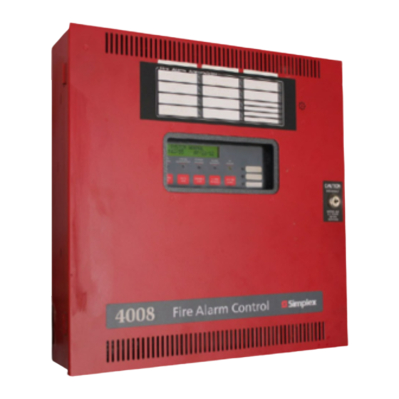
Chapter 1. Overview In This Chapter The 4008-9101 and 4008-9121 (includes door mounted annunciator) are addressable fire alarm control panels capable of monitoring and control- ling up to 200 initiating devices on an addressable communications cir- Optional Modules ..... . .1-2 cuit (IDNet). -
Page 12: Optional Modules
Chapter 1. Overview and 4008-9806 city cards are identical except that the 4006- 9805 provides disconnect switches for each circuit. Model Specification 4006-9805 must be used for Canadian applications. The City Circuit must be enabled via the panel’s System Options 120 VAC, 60 Hz, 4A;... -
Page 13: Initiating Devices
Chapter 1. Overview DETECTOR MODULES Tone-Alert Switches for ACK, Alarm Silence, System Reset, Photoelectric Detector (4098-9714, 4098-9714C) • and Lamp Test is an addressable photoelectric smoke detector that pro- vides smoke detection by means of optical sense tech- Key switch to enable switch functions nology. -
Page 14: Programming Overview
Chapter 1. Overview Multi Detector Sounder Base, Canadian (4098- It is recommended that you use the automatic program- 9795C) ming option to perform the following tasks. Multi Detector Base w/LED (4098-9796) Initial programming. After all option cards are installed and all devices are addressed and wired, Multi Detector Base w/LED, Canadian (4098- use the auto programming feature to add the cards 9796C) -
Page 15: User Interface
Chapter 1. Overview Table 1-1 Operator Keys (Continued) Photo and heat sensors mounted on sounder bases can be Function installed and programmed to act as single station smoke detectors. The sounder activates when the smoke or heat Acknowledges any unacknowledged sensor crosses its alarm threshold and turns off when the TROUBLE troubles in the system, and scrolls... -
Page 16: Logging In And Out
Chapter 1. Overview Table 1-1 Operator Keys (Continued) Table 1-2 Access Levels and Features Function Access Operation Level The <Exit/Clear> key is used to back out of menus or displays and return to the All Level 1 & 2 operations, plus: top-level menu structure. -
Page 17: Chapter 2. Installation/System Checkout
Chapter 2. Installation/System Checkout Back Box Mounting In This Chapter The back box can be surface-mounted or semi-flush mounted to the Back Box Mounting .....2-1 wall. -
Page 18: General Wiring Guidelines
Chapter 2. Installation/System Checkout • All Aux Relay loads must be powered from the AUX power circuit or from a regulated, 24 VDC, power-lim- ited power supply that is UL-listed for fire protective signaling service. Guidelines for Locating Backbox Always refer to engineering drawings/site installation plans before beginning installation. -
Page 19: Idnet Wiring
• If wiring is routed outside the building, use of a listed wiring. secondary protector is required. Use Simplex Number T-tapping is not allowed for Class A wiring. 2081-9028 or 2081-9044. A protector must be installed at each building exit/entrance. Each 2081-9028 adds .2 Compatible Detectors: ohm wiring resistance. - Page 20 Chapter 2. Installation/System Checkout IDNet Ferrite Bead Compatible Devices for use with IDNet Monitor ZAMs IDNet wiring attached to TB 2-1 and 2-2 must pass through a ferrite bead. Wrap the wiring twice through the ferrite A Zone Addressable Module (ZAM) allows the following bead, as shown in Figure 2-5.
-
Page 21: Class A/Class B Nac Wiring
• All wiring to be 18 AWG (min.) to 12 AWG (max.). and back to terminals. Use of Simplex Model 2081- 9044 will reduce the wire distance. • Conductors must test free of all grounds and stray volt- ages before connection to appliances and panel. - Page 22 Chapter 2. Installation/System Checkout TYPICAL AUDIBLE / VISIBLE APPLIANCES NAC - NAC - NAC - NAC+ NAC+ NAC+ TYPICAL AUDIBLE / VISIBLE APPLIANCES NAC - NAC - 733-894 (10K, 1/2W EOLR NAC+ NAC+ MAIN SYSTEM BOARD - ADDRESSABLE (MSB - A) Figure 2-7 NAC Wiring -- Main System Board TYPICAL AUDIBLE / VISIBLE APPLIANCES...
- Page 23 Synchronization of strobes across all NACs in a system is Multi-Candela Notification Appliances. UL-Listed for the Simplex models noted in the table below. For all other UL-Listed Notification Appliances, NACs are See the table below for maximum number allowed of each rated regulated 24 VDC at 1.5 A maximum each.
-
Page 24: Remote Annunciator Comm Wiring
• For “bus-style” wiring, maximum wiring limit is 4, 000 feet. Maximum wiring capacitance is .58 uF total, wire- to-wire plus wire to shield. Attach Simplex Model 733- Figure 2-10 Remote Annunciator 974) 100 ohm, 1/2 W harness (see “A” in figure below) Wiring Connections for line matching. -
Page 25: Digital Alarm Communicating Transmitter (Dact) Wiring
If wiring is routed outside the building, use of a listed block for connection to other telephone equipment. The secondary protector is required. Use Simplex Number DACT will seize control of the telephone line (if neces- 2081-9028 or 2081-9044. A protector must be installed sary) to transmit emergency messages. - Page 26 Chapter 2. Installation/System Checkout Table 2-4 Compatible DACRs Digital Alarm Communicator Receiver (DACR) Simplex Osborne/ SUR- SUR- Silent Silent 2, 3 ADEMCO Communication Central Hoffman Radionics GARD FBII GARD Knight Knight 1, 3 Format Station QuickAlert D6600 CP220FB MLR2-DG 9000...
-
Page 27: Auxiliary 24V Power Wiring
Chapter 2. Installation/System Checkout Auxiliary 24V Power Wiring • Compatible with Simplex 4098 Series Peripherals; 2098 Series Relay Modules; all Simplex 4090 Series IDNet • All wiring is to be 18 AWG (min.) to 12 AWG (max.) Peripherals; and 4610-9111 / 4606-9101 Annunciators. -
Page 28: City Connect Module Wiring
Refer to City Module Installation Instructions • If wiring is routed outside the building, use of a listed for details. secondary protector is required. Use Simplex Model • City module consists of two circuits that are jumper- Number 2081-9044. A protector must be installed at configured. -
Page 29: Auxiliary Relay Wiring
Chapter 2. Installation/System Checkout Auxiliary Relay Wiring • Each relay is selected for normally-closed or normally- open operation. Shunt jumper setting selects desired • All wiring must be 18 AWG (minimum) to 12 AWG contact. (maximum). • Relay 1 is programmable. Default operation is -- On •... -
Page 30: Ac Supply Wiring
Chapter 2. Installation/System Checkout AC Supply Wiring • The Expansion Power Supply (EPS) is an option, and requires AC power when used. Connect the Black/ Adhere to the following guidelines when wiring AC Power. White AC harness from the EPS to the TB4 AC input terminals on the MSB. -
Page 31: Battery Wiring
Chapter 2. Installation/System Checkout Battery Wiring • Connect the main battery harness to the four-position header, located approximately in the center of the bot- • The main battery harness connects the MSB to the bat- tom edge on the MSB. Insert the connector left-justi- tery set in the same cabinet. -
Page 32: Depleted Battery Cutout
Chapter 2. Installation/System Checkout Depleted Battery Cutout System Power-Up and Checkout For depleted battery cutout, remove the jumper shown in Use the following procedure to apply AC and battery power Figure 2-18 from the MSB. If you are using an Expansion to the 4008. -
Page 33: Replacing Lithium Battery
Chapter 2. Installation/System Checkout Testing Circuit Supervision Batteries should be tested by discharging them with a suit- able tester and verifying that battery voltage is at least 21V Use the following procedures to confirm that IDNet and when fully discharged. Battery discharge tests should be per- NACs and are supervising for opens, shorts and grounds. - Page 34 Technical Manuals Online! - http://www.tech-man.com firealarmresources.com...
-
Page 35: Configure All
Chapter 3. Auto-Programming In This Chapter The Auto-Program option provides the ability to quickly and automati- cally program the panel’s components and features for general alarm operation. It automatically scans the serial communication channel, add- Configure All......3-1 ing any annunciators found, polls the IDNet channel and configures any Detect New Hardware . -
Page 36: Detect New Hardware
Chapter 3. Auto-Programming Press <NEXT> or <PREVIOUS> until [CONFIGURE FIRE ALARM ALL] is displayed, then select it by pressing <ENTER>. SUSPENDED A warning message appears, indicating that the current Press <NEXT> or <PREVIOUS> until [RESTORE configuration will be deleted. FACTORY DEFAULT] is displayed, then select it by The display indicates the progress of the Auto Program pressing <ENTER>. -
Page 37: Restore Default System Options
Chapter 3. Auto-Programming Table 3-1 System Options (Cont’d) When the configuration is saved, the panel will automati- cally restart and run through its self-test procedure. Option Settings Default Programming Assignments Alarm Cutout Timer Choose a timer range from 0-60 min- utes (default=0 - no cutout) IDNet and NAC Default Function Types Door Drop on Alarm... - Page 38 Chapter 3. Auto-Programming Table 3-2 Default Function Type Assignments, • Tone else pulse dialing IDNet Devices, NACs, and Relays (Cont’d) • AC Fail reporting delay is 6 hours • Reporting format is CID Function Device Description • Primary and Secondary Phone Number. There are no Type values for the primary and secondary phone numbers or SIGNAL...
-
Page 39: Chapter 4. Manually Programming Idnet Points
Chapter 4. Manually Programming IDNet Points NOTICE TO INSTALLERS, AUTHORITIES HAVING JURISDICTION, AND OTHER INVOLVED PARTIES This product incorporates field-programmable software. In order for the product to comply with the requirements in the Stan- dard for Control Units and Accessories for Fire Alarm Systems, UL 864, certain programming features or options must be limited to specific values or not used at all as indicated below. -
Page 40: Accessing Idnet Programming Menus
Chapter 4. Manually Programming IDNet Points Accessing IDNet Programming Note: Make sure the address shown on the display corre- sponds to the physical address, set via dip switches, of the Menus device. Press the <MENU> key. Press <NEXT> or <PREV> Refer to “Editing IDNet Device”... - Page 41 Chapter 4. Manually Programming IDNet Points Table 4-1 Hardware Types for Sensors/Bases Table 4-1 Hardware Types for Sensors/Bases Use this Sensor Base Hardware Use this Models Models Sensor Base Type Hardware Models Models Type 4098-9754 4098-9795 4098- 4098-9795C SPHOTO & 4098-9755 9754C Multi-detector sounder base...
- Page 42 Chapter 4. Manually Programming IDNet Points Table 4-2 Hardware Types, IDNet Modules IDNet: 1 F: [Hardware Type] Use this Module Hardware Use the <NEXT> and <PREV> keys to scroll through Type the options until [Function] is displayed and then press ENTER.
- Page 43 Chapter 4. Manually Programming IDNet Points Table 4-3 Input Function Types (Continued) Table 4-3 Input Function Types (Continued) Function Function Device State = Status Device State = Status Type Type Normal = NORMAL Normal = NORMAL Current-Limited = FIRE Current-Limited = FIRE Short = FIRE Short = TROUBLE DUCT...
- Page 44 Chapter 4. Manually Programming IDNet Points Table 4-3 Input Function Types (Continued) Table 4-4 Output Function Types Function Function Device State = Status Description Type Type Normal = NORMAL Relay typically provides 24V power to larger door Current-Limited = TROUBLE holder relay with separate power source.
- Page 45 Chapter 4. Manually Programming IDNet Points Editing Point Labels The following is a list of all words in the library. Follow the steps in “Accessing Menus”. Make sure to Table 4-5 Word Library choose IDNet as the type of device to program. <ENTER>=Accept Prg: [IDNet] Default of blanks...
-
Page 46: Deleting An Idnet Point
Chapter 4. Manually Programming IDNet Points The right and left arrow keys allow you to move the focus brackets to a different alarm group, while the <NEXT> and <PREV> keys allow you to select the desired group number. Pressing <ENTER> will accept any changes made and exit, and the <EXIT/CLEAR>... -
Page 47: Chapter 5. Manually Programming Nacs, Relays, And Dact
Chapter 5. Manually Programming NACs, Relays, and DACT NOTICE TO INSTALLERS, AUTHORITIES HAVING JURISDICTION, AND OTHER INVOLVED PARTIES This product incorporates field-programmable software. In order for the product to comply with the requirements in the Stan- dard for Control Units and Accessories for Fire Alarm Systems, UL 864, certain programming features or options must be limited to specific values or not used at all as indicated below. -
Page 48: Accessing Menus
Chapter 5. Manually Programming NACs, Relays, and DACT programming NACs. Refer to Chapter 7 - “Manually Pro- • Alarm Group gramming System Options” for information on doing this. Setting NAC Function Type and Coding Pattern Accessing Menus The Function Type determines the way in which the NAC operates (whether it is an audible, visual, relay, etc.) and its Use the following steps to gain access to the NAC and relay output method (steady, etc.) - Page 49 Chapter 5. Manually Programming NACs, Relays, and DACT Table 5-1 NAC Function Types Table 5-1 NAC Function Types Function Description Type Function Description NAC activates when an initiating device with the Type following attributes activates: General Alarm Horn/Strobe (horn on-til-silence; •...
-
Page 50: Programming Aux Relays
Chapter 5. Manually Programming NACs, Relays, and DACT NAC1 NAC1 FN: [Function Type] Fn: [Alarm Groups] Use the <NEXT> and <PREV> keys until <Edit Label> Press <ENTER>. A prompt similar to the following is displayed. For example: appears. NAC1 ALARM GROUPS Fn: [Edit Label] [99] Press <ENTER>. - Page 51 Chapter 5. Manually Programming NACs, Relays, and DACT Use the <NEXT> and <PREV> keys to select the appropriate Function. Use the right arrow key to move Table 5-4 Relay Operation Settings the cursor to the coding pattern, and then use the Operation Description <NEXT>...
-
Page 52: Programming Dact
Chapter 5. Manually Programming NACs, Relays, and DACT Use the <NEXT> and <PREV> keys until <Edit Label> Press <ENTER>. The Programming menu appears. is displayed. For example: <ENTER>=Accept AUX1 Prg:[Points] Fn: [Edit Label] Press <NEXT> or <PREV> until DACT is shown. Press <ENTER>. -
Page 53: Programming Dact Options
Chapter 5. Manually Programming NACs, Relays, and DACT Programming DACT Options Note: The following special characters are available for use when setting the primary and secondary phone num- Follow the steps in “Accessing DACT Menu”. Make bers. sure to choose Options as the type of device to program. •... - Page 54 Chapter 5. Manually Programming NACs, Relays, and DACT Note: You can also use the special characters B, C, D, and E Use the NEXT and PREV keys to move from one when specifying the Secondary Phone Number. See the choice to another. Choices are tone (touchtone), pulse, description of these characters in the section “Setting Pri- and tone else pulse (attempt to dial with a touchtone for- mary Phone Number”...
-
Page 55: Programming Contact Id (Cid) Points
Chapter 5. Manually Programming NACs, Relays, and DACT AC Fail Delay Press <ENTER> to accept the choice. A prompt appears asking you to confirm the choice. The AC Fail Delay allows you to specify the interval between power loss at the panel and when the DACT noti- Press <ENTER>. -
Page 56: Programming Event Codes
Chapter 5. Manually Programming NACs, Relays, and DACT point, but there is no need to specify the type of event with <ENTER>=Accept the CID format. This information is automatically derived DACT: [Event Codes] from the point’s function type. Press <ENTER>. A prompt similar to the following Note: Default CID point values are provided in the panel. -
Page 57: Saving Changes
Chapter 5. Manually Programming NACs, Relays, and DACT Table 5-5 Event Categories and Codes (Continued) Event BFSK Manual Test Report Off-normal at test Note: Event codes for SIA and BFSK are non-editable. Saving Changes When DACT programming is complete, press the EXIT/ CLEAR key until the following prompt is shown. - Page 58 Technical Manuals Online! - http://www.tech-man.com firealarmresources.com...
-
Page 59: Chapter 6. Manually Programming Annunciators
Chapter 6. Manually Programming Annunciators In This Chapter This chapter describes • Programming LEDs on the Local Zone LED annunciator, which is a door-mounted annunciator containing 10 Red and 14 Yellow Adding an Annunciator....6-2 LEDs, providing a red alarm and yellow trouble LED for each of 10 Accessing Annunciator Menus. -
Page 60: Adding An Annunciator
Chapter 6. Manually Programming Annunciators Adding an Annunciator Press <ENTER>. Use the <NEXT> and <PREV> keys to scroll through the choices until “Add” is displayed. Automatically Adding Annunciator Cards <ENTER>=Accept Use the Automatic Programming option to automatically Annuns: [Add] add annunciator modules to the job. (This option will also detect and add an Expansion Power Supply and City Card, if Press <ENTER>. -
Page 61: Programming Leds Located On Zone Annunciator And Remote Led/Switch Modules
Chapter 6. Manually Programming Annunciators <ENTER>=Accept Prg:[IDC Use The <NEXT> and <PREV> keys to scroll to the Point 17 Point 9 Point 3 appropriate choice and then press <ENTER>. Point 20 Point 10 Point 18 • LED. Use this selection for programming the fol- Point 22 Point 11 Point 19... - Page 62 Chapter 6. Manually Programming Annunciators Table 6-2 Default LED Assignments, Remote LED/ Table 6-1 Default LED Assignments, Switch Module Local Zone LED Module Default Default Default Reference Point Type Reference LED/Color Default Function Function Point Point TROUBLE Alarm Group 9 Alarm Red LED FIRE...
- Page 63 Chapter 6. Manually Programming Annunciators Table 6-3 LED Modes <ENTER>=Accept Prg: [LED] Mode Description Press <ENTER>. A scrollable list of points appears. Output activates when referenced Use the <NEXT> and <PREV> keys to scroll to the SUPV point is in a Supervisory condition. LED point you want to edit.
-
Page 64: Programming Panel And Lcd Leds
Chapter 6. Manually Programming Annunciators Table 6-4 Common LED Reference Points (Cont’d) <ENTER>=Accept Prg: [User SW/LED] Reference Description Press <ENTER>. A scrollable list of points appears. Point Use the <NEXT> and <PREV> keys to scroll to the List contains all zones with FIRE, VERIF, point you want to edit. -
Page 65: Common Led Applications
Chapter 6. Manually Programming Annunciators Common LED Applications Setting LED Mode and Reference Point An LED’s mode allows you to specify which point is being Common applications for programmable LEDs are: monitored by the LED (called the reference point) and what •... - Page 66 Chapter 6. Manually Programming Annunciators Choosing Event Groups to Annunciate Press the <MENU> key. Press <NEXT> or <PREV> until the [Programming] option is displayed. Press After selecting <NEXT>, as described in Step 6 of the previ- <ENTER>. The following displays: ous section, you are prompted to specify whether you want to annunciate Fire events on the LCD.
-
Page 67: Saving Changes To The Job
Chapter 6. Manually Programming Annunciators Use the <NEXT> and <PREV> keys to toggle between Yes and No. Press <ENTER> when the correct value • Cont - continues the edit session. appears. Press <NEXT> to see the following prompt, • Dscrd - exits the edit session without saving your which asks if you want to require the key to use the changes (keeps the job that was loaded before you Supv Ack key. - Page 68 Technical Manuals Online! - http://www.tech-man.com firealarmresources.com...
-
Page 69: Chapter 7. Manually Programming System Options
Chapter 7. Manually Programming System Options In This Chapter System options are pre-defined modes of operation with a range of set- tings from which to choose. System Options define global operations such as the time and date format, door drop timers, and whether the city Accessing System Options Menu . - Page 70 Chapter 7. Manually Programming System Options Option Settings Option Settings The Door Holder Drop on AC Failure allows the 4008 to hold doors open for a set duration Choose 12 (am/pm) or 24-hour (military) for- Time/Date during an AC power loss condition. After that mat.
- Page 71 Chapter 7. Manually Programming System Options Option Settings This option activates the 4008 Expansion Power Supply Module and its associated NACs. If the expansion power is used in the system this option must be selected or a trou- ble will be reported. If this option is selected Enable Expan- and the EPS is not connected, the trouble will sion Power...
- Page 72 Technical Manuals Online! - http://www.tech-man.com firealarmresources.com...
-
Page 73: Chapter 8. Operating
Chapter 8. Operating Normal Operation In This Chapter The 4008 operator interface shows the following under normal condi- Normal Operation..... . .8-1 tions: LAMP Test . -
Page 74: Silencing Alarms
Chapter 8. Operating Historical Logs The 4008 is a Global Acknowledge system meaning that one The 4008 has three separate, non-volatile historical logs: press of an Acknowledge key acknowledges every abnormal Alarm, Supervisory, and Trouble. These logs can be viewed point in the system within that category. -
Page 75: Viewing And Controlling Points
Chapter 8. Operating higher. To clear the log you are currently viewing, press Press <ENTER> when the point whose status you want <ENTER> while viewing any log entry. The following to view is displayed. The Hardware Type and Function screen will be displayed: Type for the point are shown. -
Page 76: Manually Activating A Nac/Relay
Chapter 8. Operating Table 8-2 Additional Point Information (Continued) Press <NEXT> until Control/View is shown. Press <ENTER>. Use the <NEXT> or <PREV> key to Output Press <ENTER> to view a descrip- (LED) select IDC, NAC, or Relay. tion of the first system point in the list. -
Page 77: Setting The Time And Date
Chapter 8. Operating Table 8-3 Control Functions (Continued) Connect a 733-794 download cable between the Service Port on the panel and a serial communica- Function Description tion port on the PC. Create a connection profile for the serial port. Set Control Point Bypasses the following control points the serial communication parameters to 9600 baud,... -
Page 78: Walktest
Chapter 8. Operating <ENTER>=Accept If the WalkTest signaling option is set to SIG, the Menu: [Diagnostics] panel pulses the device’s zone number on the panel’s NACs. After 15 seconds the panel drops Press <ENTER>. A prompt similar to the following power to the zone, resetting the activated device. -
Page 79: Advanced Operations
Chapter 8. Operating Restarting the CPU Press the <MENU> key. Press <NEXT> or <PREV> until the [Walktest] option is displayed. Press This option is used to clear an Access Level 4 Trouble (i.e., a <ENTER>. The following displays: “Service Mode Trouble”). <ENTER>=Accept Press <MENU>. - Page 80 Technical Manuals Online! - http://www.tech-man.com firealarmresources.com...
-
Page 81: Appendix A. Battery Standby Calculations
Appendix A. Battery Standby Calculations Current Draw for System Components Each component of the 4008 system has a specified alarm and standby current rating. To calculate the current draw for the sys- tem, add the specified standby current for each module and device to obtain an alarm and a standby current rating for your sys- tem. - Page 82 20 Hour Rating C/20 (Amps) 20 Hour Rating C/20 (Amps) 2.2 Ah 0.11 7.0 Ah 0.35 3.0 Ah 0.15 7.2 Ah 0.36 3.4 Ah 0.17 10 Ah 0.50 4.0 Ah 0.20 12 Ah 0.60 4.5 Ah 0.225 12.7 Ah 0.635 5.0 Ah 0.25 18 Ah...
- Page 83 Appendix B. Contact ID Default Values Table B-1: Contact ID Default Values Event Code Description Contact ID Device 1 through GRP:01 ID:001 through Based on device Device 200 GRP:01 ID:200 function type NAC 1 GRP:01 ID:201 NAC 2 GRP:01 ID:202 Expansion NAC 1 GRP:01 ID:203 Expansion NAC 2...
- Page 84 Table B-1: Contact ID Default Values (Continued) Event Code Description Contact ID External Comm Trouble GRP:01 ID:237 Trouble DRILL GRP:01 ID:238 Utility Cold Start GRP:01 ID:239 Trouble Warm Start GRP:01 ID:240 Trouble Manual Evac GRP:01 ID:241 Alarm Time/Date Not Set GRP:01 ID:242 Trouble Service Mode...
- Page 85 Technical Manuals Online! - http://www.tech-man.com firealarmresources.com...
- Page 86 Technical Manuals Online! - http://www.tech-man.com firealarmresources.com...
Need help?
Do you have a question about the 4008-9101 and is the answer not in the manual?
Questions and answers