Table of Contents
Advertisement
Quick Links
Advertisement
Table of Contents

Related Manuals for Cypress CMIR-44


Summary of Contents for Cypress CMIR-44
- Page 1 CMIR-44 4 by 4 Infrared Matrix Operation Manual CMIR-44...
- Page 2 Cypress Technology assumes no responsibility for any inaccuracies that may be contained in this document. Cypress also makes no commitment to update or to keep current the information contained in this document.
- Page 3 Safety Precautions Please read all instructions before attempting to unpack or install or operate this equipment, and before connecting the power supply. Please keep the following in mind as you unpack and install this equipment: Always follow basic safety precautions to reduce the risk of fire, electrical shock and injury to persons.
-
Page 4: Table Of Contents
Table of Contents Introduction…………………………………………………..………. Applications……………………..…………………………....…. Package Contents…………………………..…………….....… System Requirements……...…………………..….…………..……. Features……………………………………………..……..……… Specifications..………………………………………...………...…. Hardware Description………………...……..….....…… Front Panel ................Rear Panel …………………………………………..…….… IR Cable Pin Definitions………………...……..….....…… IR Receiver................IR Blaster………………..…………………………..…….… 8.3 IR Functioning Chart………………………………………………... Remote Control …….………....…………..…..…..…... 10. Connection and Installation....…………..…..…..…... Acronyms …….………....…………..…..…...…... -
Page 5: Introduction
1. Introduction The Infrared 4 by 4 Matrix is designed to control your source devices from be- side your display/receiver. Using the original remote, you can control DVD/ Blu-ray players, satellite and set-top-boxes and with a cross matrix design this device gives the ability to send infrared signals from place to place. -
Page 6: Specifications
6. Specifications IR Frequency 30KHz to 50KHz Input port 4 x independent IR Blasters; 1 x total IR blaster control Output port 4 x independent IR Receiver; 1 x total IR receiver control Power Supply 5VDC/1A (US/EU standards, CE/FCC/UL certified) ESD Protection Human body model: ±... -
Page 7: Hardware Description
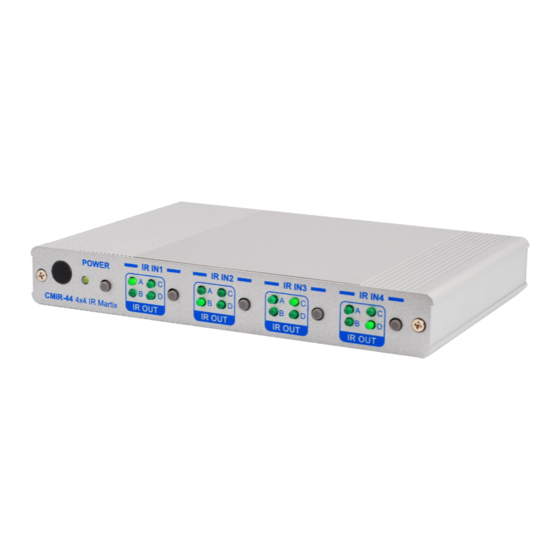
7. Hardware Description The following sections describe the hardware components of the unit. 7.1 Front Panel IR sensor: To control the system. POWER Button & LED: Press to turn the unit on or press it again to turn it to ②... -
Page 8: Rear Panel
7.2 Rear panel IR OUT ALL: This slot is where you connect the IR blaster cable included in the package. Place the IR blaster in direct line-of-sight of the equipment to be controlled for it will blaster out all signal received from IR IN 1~4. IR OUT A~D: These slots are where you connect the IR blaster ②... -
Page 9: Ir Cable Pin Definitions
8. IR Cable Pin Definitions 8.1 IR Receiver 8.2 IR Blaster IR Receiver IR Blaster ① Power 5V ① IR signal ② IR Blaster Signal ② Power 5V ③ NC ③ Grounding ① ② ③ ① ② ③ Note: Both the IR Receiver & Blaster can support a frequency of 30~50KHz. -
Page 10: Remote Control
9. Remote Control POWER 1. Power: Press the button to turn on/ standby the unit. INPUT 2. IR input 1: Select for IR OUT A~D: Press A, B, C or D to select the INPUT desired IR out for sending a signal. 3. -
Page 11: Connection And Installation
IR Blaster B IR Blaster A ► extend 3.5mm ST female to male ear phone jack cable up to 10M CMIR-44 ► extend 3.5mm ST female to male ear phone jack cable up to 10M IR Receiver 4 IR Receiver 2... -
Page 12: Acronyms
Acronyms Acronym Complete Term Infrared CYPRESS TECHNOLOGY CO., LTD. Home page: http://www.cypress.com.tw 20100204 MPM-CMIR44...
Need help?
Do you have a question about the CMIR-44 and is the answer not in the manual?
Questions and answers