Cypress CY8CKIT-001 User Manual
Psoc thermal management kit
Hide thumbs
Also See for CY8CKIT-001:
- Manual (211 pages) ,
- Development kit manual (116 pages) ,
- Quick start manual (2 pages)
Table of Contents

Related Manuals for Cypress CY8CKIT-001


Summary of Contents for Cypress CY8CKIT-001
-
Page 2: Table Of Contents
4.1 Introduction ..............................19 4.2 System Requirements ..........................19 4.3 Software Installation..........................19 4.4 Hardware Setup: CY8CKIT-001 PSoC Development Kit (PSoC DVK) ..........21 4.5 Hardware Setup: CY8CKIT-030 PSoC3 Development Kit (PSoC 3 DVK)..........22 4.6 Example Projects ............................23 4.7 Running the Example Firmware: CY8CKIT-001 PSoC DVK...............24 4.8 Running the Example Firmware: CY8CKIT-030 PSoC 3 DVK ............25... - Page 3 Appendix .........................45 Chapter 5 5.1 Revision History............................45 5.2 Copyright Statement ..........................45...
-
Page 4: Introduction Of The Tme Board
The PSoC Thermal Management Expansion Board Kit (EBK) is a part of the PSoC development kit ecosystem and is designed to work with the CY8CKIT-001 PSoC Development Kit (DVK) and CY8CKIT-030 PSoC 3 Development Kit (DVK). It enables you to evaluate a system’s thermal management functions and capabilities of PSoC 3 devices. -
Page 5: Features
Features Features The PSoC Thermal Management EBK is intended to provide a demonstration and development platform for developing system environmental management co-processor solutions with compelling example projects that demonstrate a variety of modes: Temperature monitoring Independent and closed-loop fan controls Thermal-management specific communications Thermal zone management—the relationship between temperatures and cooling functions Algorithms to detect thermal and cooling failures or warnings. -
Page 6: About The Kit
System CD-ROM containing: User Guide PSoC Creator and prerequisite software PSoC Programmer and prerequisite software PME Example firmware For the CY8CKIT-001 DVK Firmware based (open loop) Fan Control Hardware based (closed loop) Fan Control Thermal Management System For the CY8CKIT-030 DVK... -
Page 7: Getting Help
Figure 1-2 TME kit package contents PSoC Creator PSoC Creator Cypress's PSoC Creator software is a state-of-the-art, easy-to-use integrated development environment (IDE) that introduces a game-changing, hardware and software design environment based on classic schematic entry and revolutionary embedded design methodology. -
Page 8: Tme Board Architecture
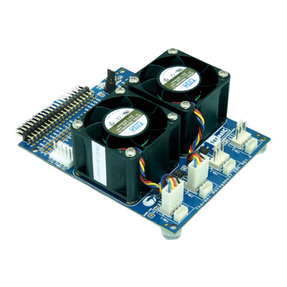
Chapter 2 TME Board Architecture This chapter provides information about architecture and block diagram of the TME board. Layout and Components Layout and Components The picture of the TME board is shown in Figure 2-1 Figure 2-2. It depicts the layout of the board and indicates the locations of the connectors and key components. -
Page 9: Block Diagram Of The Tme Board
Figure 2-2 The TME Board PCB and component diagram (bottom view) Block Diagram of the TME Board Block Diagram of the TME Board Figure 2-3 shows a functional diagram of the PSoC Thermal Management solution. This solution enables control of up to 16 4-wire fans through CPU based firmware control (open-loop), hardware control (closed-loop) all as a function of system temperatures (f(T)), all on a single chip. - Page 10 A 40-pin connector is provided on the EBK to route the input/output signals for thermal management control to the PSoC on the host development board (such as the CY8CKIT-001 or CY8CKIT-030). This connector carries power, fan PWM control and tachometer data lines, analog and digital temperature sensor signals.
- Page 11 The demonstration projects included with this kit show I2C digital temperature sensing and diode analog temperature sensing (simulated via a potentiometer). The remaining components are described in Cypress’s Application Notes and are referenced in the corresponding sections of this User’s Manual.
-
Page 12: Chapter 3 Board Component
Chapter 3 Board Component This chapter describes the specifications of the components used on the PSoC Thermal Management EBK. 40-pin Connector(J14) 40-pin Connector(J14) The 40-pin interface (2×20 pin header) provides a mechanism to extend the peripheral-set of a PSoC host board by means of a general purpose input output connector. Figure 3-1 shows the pin names defined on the GPIO connector (J14) on the Thermal Management EBK. -
Page 13: Pwm Temperature Sensor
Table 3-1 Pin assignments and descriptions on GPIO connector Pin Numbers Name PSoC Description TACH4 P1.7 Fan 4’s tach reading PWM4 P1.6 Fan 4’s PWM signal TACH3 P1.5 Fan 3’s tach reading PWM3 P1.4 Fan 3’s PWM signal TACH2 P1.3 Fan 2’s tach reading PWM2 P1.2... - Page 14 Dual modes for PWM Temperature Sensor. Place jumper in 1-2 position to enable Dual PWM mode. 3 pin header for VDDIO power jumper. Place 2-3 position in 1-2 to VDD5. Place in 2-3 position to VDD3P3 4 pin header (1.25mm pitch) to connect Fan 1 Not connected –...
- Page 15 This kit is compatible with both the PSoC Development Kit - CY8CKIT-001B and the PSoC 3 Development Kit – CY8CKIT-030. Note early revisions of the PSoC Development Kit (CY8CKIT-001 or CY8CKIT-001A) contained an early engineering release of the PSoC CY8C38 Device Family Processor Module (ES2) which is not compatible with the example projects that accompany this kit.
-
Page 16: I2C Temperature Sensor
40-pin header to the sensors on the EBK. TMP05 Module Connection Cypress’s Application Note AN65977 – “Interfacing to a TMP05/06 Digital Temperature Sensor with PSoC 3” describes in detail how to interface to digital sensors that encode the measured temperature into a pulse-width-modulated (PWM) signal. -
Page 17: 1-Wire Temperature Sensor
100mA as a switch and to 100MHz as an amplifier. The de lta Vbe method described in Cypress Application Note AN60590 – “Temperature Measurement Using Diode” can be used in this design. Refer to that application note for the theory of operati on and relevant mathematical equations. -
Page 18: 4-Wire Fan Socket
Figure 3-5 Diode Analog Temperature Sensor 4-Wire Fan Socket 4-Wire Fan Socket The TME board provides four industry standard 4-wire interface connectors, and two AVC DC fans. The fan speeds are controllable up to 13,000 RPMs via PWM control, with frequency generator signal output to calculate actual fan speeds or the tachometer reading. - Page 19 Figure 3.7 Block diagram of Fan Controller...
-
Page 20: Demonstrations On Tme
This demonstration shows how to use the PSoC kit to control the TME board. System Requirements System Requirements The following items are required for the TME demonstration: CY8CKIT-001 PSoC Development Kit or CY8CKIT-030 PSoC 3 Development Kit TME board DC 12V/2A Power Adapter (included with the TME kit) Software Installation... - Page 21 Follow the instructions to uninstall. Kit Compatibility This kit contains an expansion board and requires a Cypress host development board in order to use it. This kit is compatible with both the PSoC Development Kit - CY8CKIT-001B and the PSoC 3 Development Kit –...
-
Page 22: Hardware Setup: Cy8Ckit-001 Psoc Development Kit (Psoc Dvk)
Figure 4-2 CY8CKIT-001 PSoC DVK Breadboard 2. Set “VDD DIG” and “VDD ANLG” to 3.3V using SW3, J6 and J7: Figure 4-3 CY8CKIT-001 PSoC DVK Power Jumpers 3. Ensure that the LCD character display included with PSoC DVK is attached and that the LCD... -
Page 23: Hardware Setup: Cy8Ckit-030 Psoc3 Development Kit (Psoc 3 Dvk)
Figure 4-4 CY8CKIT-001 PSoC DVK LCD Power Jumper CAUTION: Do not attach the PSoC Thermal Management EBK to the PSoC DVK until you have programmed the PSoC with one of the example projects. Some of the GPIOs routed to the PSoC Thermal Management EBK are tied to ground and this could cause hard shorts on PSoC I/O pins if firmware previously programmed into PSoC drives those pins. -
Page 24: Example Projects
Closed-Loop Hardware Fan Control Thermal Management System The kit includes project workspaces for both the CY8CKIT-001 PSoC DVK and the CY8CKIT-030 PSoC 3 DVK. To begin, go to the Start Page in PSoC Creator and under the Examples and Tutorials section, expand The Kits and Solutions entry as shown below. -
Page 25: Running The Example Firmware: Cy8Ckit-001 Psoc Dvk
Figure 4-7 PSoC Creator Start Page The example projects will be displayed in the Workspace Explorer window as shown in the example below for the CY8CKIT-001 PSoC DVK: Figure 4-8 Workspace Explorer View Running the Example Firmware: CY8CKIT-001 Running the Example Firmware: CY8CKIT-001... -
Page 26: Running The Example Firmware: Cy8Ckit-030 Psoc 3 Dvk
PSoC DVK. Once the PSoC DVK is powered and the PSoC firmware is running, PSoC may be re-programmed at any time without removing power from either board. Figure 4-9 CY8CKIT-001 PSoC DVK with PSoC Thermal Management EBK Connected to Port A... -
Page 27: Overview Of Example1 - Firmware Based Fan Control
6. Re-attach a USB cable from the PC to the PSoC 3 DVK Program/Debug USB port (use J1 - the USB connector closest to the corner of the board). 7. Going forward, every time PSoC is re-programmed, press the Reset (SW1) button on the PSoC 3 DVK to run the newly programmed firmware image. -
Page 28: Technical Details For Example1
The user can adjust the desired speed up or down in steps of 500 RPM by pressing buttons on the DVK as follows: CY8CKIT-001 PSoC DVK : SW1=Decrease Speed, SW2=Increase Speed CY8CKIT-030 PSoC 3 DVK: SW2=Decrease Speed, SW3=Increase Speed A firmware algorithm responds to changes in desired speed by adjusting the duty cycle for both fans and continuously works at fine tuning the duty cycle until the actual fan speeds approach the desired speed. - Page 29 Figure 4-12 Example1 Project Schematic The Fan Controller Component can be configured by double-clicking on it in the Top Level schematic for Example 1. This will open the customizer Basic Tab. For this example, ensure that the control mode is set to Fireware (CPU). Other options are not important for this example.
- Page 30 Figure 4-13 Example1 Project Fan Controller Customizer – Basic Tab Click on the Fans Tab to setup the electromechanical properties of the fans installed on the PSoC Thermal Management EBK. The Min RPM, Min Duty (%) and the Max RPM, Max Duty (%) parameters are not intended to define the absolute upper and lower limits of fan operation or capability.
- Page 31 Figure 4-14 Example1 Project Fan Controller Customizer – Fans Tab Firmware is able to control the fans using these provided Fan Controller Component APIs: FanController_Start() FanController_GetActualSpeed(FanNumber) FanController_SetDutyCycle(FanNumber,DutyCycle) The time taken to measure the actual speeds of each fan is long, particularly for slow rotational speeds.
-
Page 32: Overview Of Example2 - Closed Loop Hardware Fan Control
Note: that the eoc signal in this project is also routed to a GPIO (P0.0) so that it can be observed on a scope or logic analyzer. 4.11 Overview of Example2 – Closed Loop Hardware Fan 4.11 Overview of Example2 – Closed Loop Hardware Fan Control Control The purpose of this example is to demonstrate the Fan Controller Component controlling the two... -
Page 33: Technical Details Example2
4.12 Technical Details Example2 4.12 Technical Details Example2 The fan control portion of the Example 2 Top Level Schematic is shown below: Figure 4-16 Example2 Project Schematic Example 2 implements a hardware controlled closed-loop fan controller using the Fan Controller Component in Closed Loop control mode. - Page 34 Figure 4-17 Example2 Project Fan Controller Customizer – Basic Tab Once either of the Alerts has been enabled, the Fan Controller will assert the alert pin (high) when the enabled condition occurs (and for as long as it persists) on any of the fans. In this example, the alert pin has been tied to a standard ISR Component.
-
Page 35: Overview Of Example3- Thermal Management System
90% weight and the digital I2C temp sensor (U1 on the EBK) is given 10% weight. Adjust the potentiometer (R20 on the CY8CKIT-001 PSoC Development Kit and R56 on the CY8CKIT-030 PSoC 3 Development Kit) to vary the simulated temperature value in the approximate range of 15 to 100 degrees C. - Page 36 In this example, The LCD screen displays status information about thermal management system across 3 screes. The user can cycle through the status screens by pressing SW1 on the CY8CKIT-001 PSoC Development Kit or SW2 on the CY8CKIT-030 PSoC 3 Development Kit. The three screens are:...
-
Page 37: Technical Details Example3
1. Screen 1 - Zone 1 Summary This screen displays the current status of Zone 1. Line 1 displays the zone number, the current zone temperature and the zone temperature calculation algorithm used. Line 2 displays the desired fan speed and the actual fan speed. Figure 4-20 Example3 Screen 1 Display 2. - Page 38 The example projects provided use a custom PSoC Creator component that is not included with the standard PSoC Creator Software install. This component is the Fan Controller. More information and additional example firmware for this component is available in the following Application Note from Cypress: AN66627 - PSoC® 3 and PSoC 5 Intelligent Fan Controller...
- Page 39 4.16 Using the Components in Your Own Projects 4.16 Using the Components in Your Own Projects The Fan Controller Component is provided in Library form so that you can easily add it to your own projects. To do so, you need to add the Library as a system dependency to your project. With your project open in PSoC Creator: 1.
- Page 40 Chapter 5 Schematics Power supply Power supply Power VDD12 Default : VDD12 VDD12_EXT VDD12_EXT VDD12 VDD12 <-> VDD12_EXT VDD12 SM340A VDD12_EXT VDD12_DVK DC-12V VDD12 SM340A VDD12_DVK 0.1u 12V/3A JMP-3 SM340A VDD12 SM340A Default : VDD5 VDD3P3 VDD5 VDD5 VDD3P3 VDDIO DGND AGND VDDIO <->...
- Page 41 I2C/SMBus Port I2C/SMBus Port VDDIO SMBUS_SDA SM_SDA SMBUS_SCL SM_SCL SMBUS_ALERT_n SM_ALT SM_GND VDDIO I2C/SMBus Port 40 Pin Connector 40 Pin Connector Config Pin 2 4 6 8 Debug & Signal Probe Port to OC Output Mode TACH4 PWM4 TACH4 PWM4 TACH PWM4 TACH...
- Page 42 I2C Temperature Sensor I2C Temperature Sensor VDDIO VDDIO 2.2K 2.2K 0.1u I2C-TEMP_SDA I2C-TEMP_SCL ALERT TMP175 I2C Address 8'b01001000 PWM Temperature Sensor PWM Temperature Sensor VDDIO VDDIO PWM-IN CONV/IN 0.1u FUNC SINGLE PWM-OUT TMP05 PWM_TMP DUAL JMP-3 Default : PWM_TMP <-> DUAL CONV/IN 0.1u FUNC...
- Page 43 Layout Layout...
- Page 44 5.10 Bill of Materials 5.10 Bill of Materials Quanti Manufacturer Item Description Designator Value Manufacturer Part# C2,C5,C7,C1 Ceramic 1,C12,C13,C Capacitor 14,C15,C16, TMK105BJ104 0.1uF, +/-10%, 0.1u Taiyo Yuden C17,C18,C19 KV-F 25V, ,C20,C21,C2 X5R(0402) 22uF, +/-10%, GRM32ER61E2 25V, MURATA 26KE15L X5R(1210) 10uF, +/-10%, GRM31CR61E1 25V, C9,C10,C23...
- Page 45 2.54mm Wire-to-Board PITCH Header, 180° Type Power DC-12 CHERNG WEEI 32753PA Socket Header, 2X20, Pitch CON4 2.54MM, male, Right Angel General MMBT Purpose Q1,Q2 Fairchild MMBT3094 3094 Amplifier ohm, RC0402FR-071 +/-1%, YAGEO 1/16W(0402) 2.2K ohm, RC0402FR-072 +/-1%, R2,R3 2.2K YAGEO 1/16W(0402)_ 4.7K ohm,...
-
Page 46: Revision History
Chapter 6 Appendix Revision History Revision History Version Change Log V1.0 Initial Version (Preliminary) Copyright Statement Copyright Statement Copyright © 2011 Terasic Technologies. All rights reserved.
Need help?
Do you have a question about the CY8CKIT-001 and is the answer not in the manual?
Questions and answers