Table of Contents
Advertisement
Quick Links
Advertisement
Table of Contents

Related Manuals for Cypress CY8CKIT-017


Summary of Contents for Cypress CY8CKIT-017
- Page 1 CY8CKIT-017 CAN/LIN Expansion Board Kit Guide Doc. # 001-57814 Rev. *B Cypress Semiconductor 198 Champion Court San Jose, CA 95134-1709 Phone (USA): 800.858.1810 Phone (Intnl): 408.943.2600 http://www.cypress.com Downloaded from Elcodis.com electronic components distributor...
- Page 2 Cypress Source Code and derivative works for the sole purpose of creating custom soft- ware and or firmware in support of licensee product to be used only in conjunction with a Cypress integrated circuit as speci- fied in the applicable agreement.
-
Page 3: Table Of Contents
Port Options with CY8CKIT-001 DVK................22 4.5.1 Jumper Settings of CY8CKIT-001 DVK for Using Port B .......23 4.5.2 Debugging Restrictions When Using Port B ..........23 CY8CKIT-017 CAN/LIN Expansion Board Kit Guide, Doc. # 001-57814 Rev. *B Downloaded from Elcodis.com electronic components distributor... - Page 4 5.1.4.12 CAN_LED_WARN ................40 5.1.4.13 CAN_LED_ERR ................41 5.1.4.14 Design Wide Resources ..............42 Example Project 2: CAN_Example_2................ 44 A. Appendix Schematic........................45 BOM .......................... 46 CY8CKIT-017 CAN/LIN Expansion Board Kit Guide, Doc. # 001-57814 Rev. *B Downloaded from Elcodis.com electronic components distributor...
-
Page 5: Introduction
Introduction The CY8CKIT-017 CAN/LIN Expansion Board Kit (EBK) is an expansion board that is used with the ® CY8CKIT-001 PSoC Development Kit (DVK), the CY8CKIT-030 PSoC 3 Development Kit (DVK), or the CY3280-22X45 Universal CapSense Controller (UCC) kit. It enables you to evaluate the Controller Area Network (CAN) communication capability of PSoC 3 and PSoC 5 devices. -
Page 6: Psoc Creator
LIN node in order to set up communication between nodes. Therefore, it is recommended to have two CY8CKIT-001 DVK kits and two CY8CKIT-017 EBK kits. This enables you to setup CAN or LIN communication between two CAN or LIN nodes. An alternate recommendation is to have a CAN or LIN bus emulator or analyzer. -
Page 7: Technical Support
Introduction Technical Support If you have any technical questions or issues related to this kit, call Cypress Customer Support +1 (800) 541-4736 Ext. 8 (in the USA), +1 (408) 943-2600 Ext. 8 (International), or visit www.cypress.com/go/support Document History Release Date... - Page 8 Introduction CY8CKIT-017 CAN/LIN Expansion Board Kit Guide, Doc. # 001-57814 Rev. *B Downloaded from Elcodis.com electronic components distributor...
-
Page 9: Installation
2.2.2 Installation From Internet Follow these steps to install the CY8CKIT-017 CAN/LIN EBK software from the internet (this can be done to ensure that the latest software is installed): 1. Insert the kit CD into your computer. 2. Choose the Install the latest kit contents from web option on the auto run screen. This will direct you to a web page where the latest installer can be downloaded. -
Page 10: Software Uninstallation
Software Uninstallation Follow these steps to uninstall the CY8CKIT-017 CAN/LIN EBK software: 1. Open the Cypress Update Manager program. This is a program that is installed along with other Cypress software. 2. Click the Uninstall button associated with the CY8CKIT-017 kit software. -
Page 11: Kit Operation
Note Most of the information in this section describes kit operation when two CYC8KIT-001 DVK kits and two CY8CKIT-017 EBK kits are available. If only one CY8CKIT-001 DVK kit and one CY8CKIT- 017 EBK kit are available, see... - Page 12 5. Create a folder in the desired location and click OK. The project opens in PSoC Creator and is saved in that folder. 6. Build the project by selecting the Build option. CY8CKIT-017 CAN/LIN Expansion Board Kit Guide, Doc. # 001-57814 Rev. *B Downloaded from Elcodis.com...
- Page 13 10.Follow the same steps (1 through 9) to program the second PSoC 3 (on a CY8CKIT-001 DVK with a second CY8CKIT-017 CAN/LIN EBK) with the 'CAN_Example_2' project. CY8CKIT-017 CAN/LIN Expansion Board Kit Guide, Doc. # 001-57814 Rev. *B Downloaded from Elcodis.com...
-
Page 14: Hardware Connections
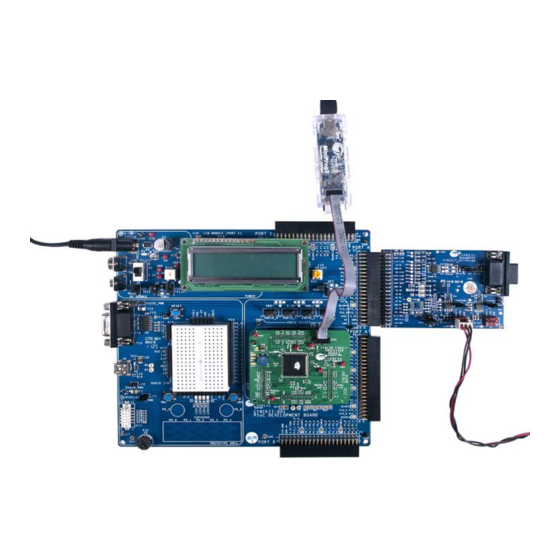
1. Connect the CAN/LIN Expansion Board to port A of CY8CKIT-001 DVK, as shown in Figure 3-6. Figure 3-6. Board Connected to Port A 2. Connect a second CY8CKIT-017 Expansion Board to Port A of a second CY8CKIT-001 DVK, as shown in Figure 3-6. - Page 15 7. Power up one DVK board with the 12V power supply. Then power up the other DVK with a 12V power supply. The second DVK must be powered up within about 5 seconds of powering the first DVK. CY8CKIT-017 CAN/LIN Expansion Board Kit Guide, Doc. # 001-57814 Rev. *B Downloaded from Elcodis.com...
-
Page 16: Verify The Functionality
Figure 3-10. Verifying LCD Output of CAN_Example_1 project Using a CAN Bus Analyzer Tool This kit functions most effectively when two CY8CKIT-001 DVK kits and two CY8CKIT-017 EBK kits are available. However, it is also possible to replace one CY8CKIT-001 DVK kit and one CY8CKIT- 017 EBK kit with a CAN bus analyzer or emulator tool. -
Page 17: Hardware
LEDs are driven by PSoC pins. The 40-pin (2 x 20) connector connects the configured PSoC I/O pins to the various circuits on the Expansion Board. CY8CKIT-017 CAN/LIN Expansion Board Kit Guide, Doc. # 001-57814 Rev. *B Downloaded from Elcodis.com... -
Page 18: Can Physical Layer Transceiver Circuit
By default, pin 9 of the CAN connector is left floating. However, if the "CANEXTPWR" jumper (JP3) is populated, pin 9 of the CAN connector is connected to the VIN power rail of the DVK and EBK. CY8CKIT-017 CAN/LIN Expansion Board Kit Guide, Doc. # 001-57814 Rev. *B Downloaded from Elcodis.com... -
Page 19: Can Bus Termination
CAN circuit does not interfere with any other circuits that share the same pins. The footprints for R3, R5, and R10 are designed so that they can be reconnected easily with a "solder jumper" instead of repopulating the footprints with a 0 resistor. CY8CKIT-017 CAN/LIN Expansion Board Kit Guide, Doc. # 001-57814 Rev. *B Downloaded from Elcodis.com... -
Page 20: Lin Physical Layer Transceiver Circuits
R23, R25, R20, R24, and R26 are designed so that they can be reconnected easily with a "solder jumper" instead of repopulating the footprints with a 0 resistor. CY8CKIT-017 CAN/LIN Expansion Board Kit Guide, Doc. # 001-57814 Rev. *B Downloaded from Elcodis.com... -
Page 21: Using The Lin Transceiver Nwake Pins
EBK are. In this case, isolating the LEDs ensures that they do not interfere with any other circuits that share the same pins. CY8CKIT-017 CAN/LIN Expansion Board Kit Guide, Doc. # 001-57814 Rev. *B Downloaded from Elcodis.com... -
Page 22: Port Options With Cy8Ckit-001 Dvk
P12_3 P12_3 P12_2 P12_2 P12_2 P12_1 P12_1 P12_1 P12_0 P12_0 P12_0 V3_3 V3_3 V3_3 V3_3 VADJ VADJ VADJ VADJ V5_0 V5_0 V5_0 V5_0 CY8CKIT-017 CAN/LIN Expansion Board Kit Guide, Doc. # 001-57814 Rev. *B Downloaded from Elcodis.com electronic components distributor... -
Page 23: Jumper Settings Of Cy8Ckit-001 Dvk For Using Port B
VIN power supply of the DVK. One reason to use this would be if there are two CY8CKIT-001 boards (both with CY8CKIT-017 EBKs) that are connected to each other between their CAN connectors or LIN connectors. In this case, it is useful to allow the VIN power supply of one DVK to power up the other DVK (and its EBK) through the LIN or CAN header. -
Page 24: Default Switch And Jumper Settings
Hardware Default Switch and Jumper Settings Jumpers on the CY8CKIT-017 CAN/LIN Expansion Board have a default setting for 5V operation. For Default configuration, each of the jumpers must be set according to these instructions (any jump- ers on the board not mentioned below should have no jumper installed). -
Page 25: Example Projects
Example Projects The CAN_Example_1 project demonstrates the implementation of a CAN node using a CY8CKIT- 001 DVK, a CY8CKIT-009 PSoC 3 processor module, and a CY8CKIT-017 CAN/LIN EBK. The test setup shown in Figure 3-9 on page 15 consists of two CAN nodes, created using two CY8CKIT-001 DVKs, two CY8CKIT-009 PSoC 3 processor modules, and two CY8CKIT-017 CAN/LIN EBKs con- nected by a DB9 cable. - Page 26 RxError == 0 and Red TxError > 127 or Turn On Red, RxError > 127 Turn Off Amber Turn On Amber, Turn Off Red CY8CKIT-017 CAN/LIN Expansion Board Kit Guide, Doc. # 001-57814 Rev. *B Downloaded from Elcodis.com electronic components distributor...
-
Page 27: Running The Example Project
PSoC Creator offers a flexible hardware and software co-design environment to create and configure the programmable peripherals. Figure 5-3. PSoC Creator Top Level Design For CAN_Example_1 Project CY8CKIT-017 CAN/LIN Expansion Board Kit Guide, Doc. # 001-57814 Rev. *B Downloaded from Elcodis.com... -
Page 28: Can
Any tabs not shown have default settings. This is valid for all components of all example projects. Figure 5-4. CAN Configuration: General Tab Figure 5-5. CAN Configuration: Timing Tab CY8CKIT-017 CAN/LIN Expansion Board Kit Guide, Doc. # 001-57814 Rev. *B Downloaded from Elcodis.com electronic components distributor... - Page 29 Example Projects Figure 5-6. CAN Configuration: Interrupt Tab Figure 5-7. CAN Configuration: Receive Buffers Tab CY8CKIT-017 CAN/LIN Expansion Board Kit Guide, Doc. # 001-57814 Rev. *B Downloaded from Elcodis.com electronic components distributor...
-
Page 30: Adc
Figure 5-8. CAN Configuration: Transmit Buffers Tab 5.1.4.2 The ADC component is used to sample the potentiometer input. Figure 5-9. ADC Configuration: Configure Tab CY8CKIT-017 CAN/LIN Expansion Board Kit Guide, Doc. # 001-57814 Rev. *B Downloaded from Elcodis.com electronic components distributor... - Page 31 Example Projects Figure 5-10. ADC Configuration: Common Tab CY8CKIT-017 CAN/LIN Expansion Board Kit Guide, Doc. # 001-57814 Rev. *B Downloaded from Elcodis.com electronic components distributor...
-
Page 32: Pot_In
High Impedance Analog, which is the default value. Figure 5-11. POT_IN Configuration: Pins > Type Tab Figure 5-12. POT_IN Configuration: Pins > General Tab CY8CKIT-017 CAN/LIN Expansion Board Kit Guide, Doc. # 001-57814 Rev. *B Downloaded from Elcodis.com... -
Page 33: Status_Reg
The BUS_CLK is used as the latching clock for the STATUS_REG component. This is an existing, high-frequency clock in the chip. Figure 5-14. BUS_CLK Configuration: Configure Clock Tab CY8CKIT-017 CAN/LIN Expansion Board Kit Guide, Doc. # 001-57814 Rev. *B Downloaded from Elcodis.com... -
Page 34: Loopclk
LOOPCLK is configured to generate a 100 Hz clock, which is used to generate a 10 ms period in the firmware. Figure 5-15. LOOPCLK Configuration: Configure Clock Tab Figure 5-16. LOOPCLK Configuration: Advanced Tab CY8CKIT-017 CAN/LIN Expansion Board Kit Guide, Doc. # 001-57814 Rev. *B Downloaded from Elcodis.com electronic components distributor... -
Page 35: Lcd
CAN_TX is the CAN bus transmit signal pin. This pin is configured as an output pin with a strong drive mode. It must be connected to the CAN TX input of the external CAN transceiver. Figure 5-18. CAN_TX Configuration: Pins > Type Tab CY8CKIT-017 CAN/LIN Expansion Board Kit Guide, Doc. # 001-57814 Rev. *B Downloaded from Elcodis.com... -
Page 36: Can_Rx
CAN_RX is the CAN bus receive signal pin. This pin is configured as an input pin with a high imped- ance drive mode. It must be connected to the CAN RX pin of the external CAN transceiver. Figure 5-20. CAN_RX Configuration: Pin > Type Tab CY8CKIT-017 CAN/LIN Expansion Board Kit Guide, Doc. # 001-57814 Rev. *B Downloaded from Elcodis.com... - Page 37 Example Projects Figure 5-21. CAN_RX Configuration: Pins > General Tab Figure 5-22. CAN_RX Configuration: Pins > Input Tab CY8CKIT-017 CAN/LIN Expansion Board Kit Guide, Doc. # 001-57814 Rev. *B Downloaded from Elcodis.com electronic components distributor...
-
Page 38: Can_En
CAN_EN is external CAN transceiver enable signal pin. This pin is configured as an output pin with strong drive mode. Figure 5-23. CAN_EN Configuration: Pins > Type Tab Figure 5-24. CAN_EN Configuration: Pins > General Tab CY8CKIT-017 CAN/LIN Expansion Board Kit Guide, Doc. # 001-57814 Rev. *B Downloaded from Elcodis.com electronic components distributor... -
Page 39: Can_Led_Ok
CAN_LED_OK CAN_LED_OK is configured as a software controlled output pin with strong drive mode and initial state as high. This pin is connected to the green LED on the CY8CKIT-017 CAN/LIN EBK. Figure 5-25. CAN_LED_OK Configuration: Pins > Type Tab Figure 5-26. -
Page 40: Can_Led_Warn
CAN_LED_WARN CAN_LED_WARN is configured as a software controlled output pin with strong drive mode and initial state as high. This pin is connected to the amber LED on the CY8CKIT-017 CAN/LIN EBK. Figure 5-27. CAN_LED_WARN Configuration: Pins > Type Tab Figure 5-28. -
Page 41: Can_Led_Err
CAN_LED_ERR CAN_LED_ERR is configured as a software controlled output pin with strong drive mode and initial state as high. This pin is connected to the red LED on the CY8CKIT-017 CAN/LIN EBK. Figure 5-29. CAN_LED_ERR Configuration: Pins > Type Tab Figure 5-30. -
Page 42: Design Wide Resources
PSoC CAN controller. All of the clock settings of this example project are shown in Figure 5-32 Figure 5-33 on page CY8CKIT-017 CAN/LIN Expansion Board Kit Guide, Doc. # 001-57814 Rev. *B Downloaded from Elcodis.com electronic components distributor... - Page 43 Example Projects Figure 5-32. Clock setting Figure 5-33. System Clock Configuration CY8CKIT-017 CAN/LIN Expansion Board Kit Guide, Doc. # 001-57814 Rev. *B Downloaded from Elcodis.com electronic components distributor...
-
Page 44: Example Project 2: Can_Example_2
CAN_Example_1 project also apply to the CAN_Example_2 project except Figure 5-7 on page 29 Figure 5-8 on page 30 where the transmit message ID and receive message ID are interchanged. CY8CKIT-017 CAN/LIN Expansion Board Kit Guide, Doc. # 001-57814 Rev. *B Downloaded from Elcodis.com electronic components distributor... -
Page 45: Appendix
Appendix Schematic CY8CKIT-017 CAN/LIN Expansion Board Kit Guide, Doc. # 001-57814 Rev. *B Downloaded from Elcodis.com electronic components distributor... -
Page 46: Bom
U2,U3 IC LIN TRANSCEIVER 8-SOIC NXP Semiconductors TJA1020T/N1,112 TEST POINT 43 HOLE 65 PLATED WHITE TP19(GND..) Keystone Electronics 5002 (0.040" (1.016mm) Hole Diameter) CY8CKIT-017 CAN/LIN Expansion Board Kit Guide, Doc. # 001-57814 Rev. *B Downloaded from Elcodis.com electronic components distributor...
Need help?
Do you have a question about the CY8CKIT-017 and is the answer not in the manual?
Questions and answers