Table of Contents
Advertisement
Quick Links
Advertisement
Table of Contents

Subscribe to Our Youtube Channel
Related Manuals for Pepperl+Fuchs SC4-2


Summary of Contents for Pepperl+Fuchs SC4-2
- Page 1 FACTORY AUTOMATION INSTRUCTION MANUAL INSTRUCTION MANUAL CONTROL UNIT SC4-2...
- Page 2 With regard to the supply of products, the current issue of the following document is applicable: The General Terms of Delivery for Products and Services of the Electrical Industry, published by the Central Association of the Electrical Industry (Zentralverband Elektrotechnik und Elektroin- dustrie (ZVEI) e.V.) in its most recent version as well as the supplementary clause: "Expanded reservation of proprietorship"...
-
Page 3: Table Of Contents
The SC4-2 control unit........ - Page 4 Sample circuits for SC4-2 ........
- Page 5 Pepperl+Fuchs. The warrantee undertaken by Pepperl+Fuchs for this product becomes null and void if it is not used, cared for, maintained and monitored in accordance with the instructions of Pepperl+Fuchs.
- Page 6 Destruction of basic components caused by an electrostatic discharge voids the warrantee! Symbols used This manual uses symbols to present important information on operating the SC4-2 and working safely with it. The meaning of these symbols is as follows: Recommendation for the user Observing these notes will make it easier to place the system in operation and to work with the SC4-2.
-
Page 7: Sc4 Control System
Control unit SC4-2 SC4 control system 14.1 Intended use In combination with light barriers of type SLA, the SC4 control system represents a photoelectric protective device. Protective beams are formed between transmitters and receivers. This system must only be used in accordance with intended purpose as electrosensitive pro- tection device for securing access to hazardous points and areas. -
Page 8: Declaration Of Conformity
This product was developed and manufactured under observance of the applicable European standards and guidelines. Note! A Declaration of Conformity can be requested from the manufacturer. The product manufacturer, Pepperl+Fuchs GmbH, D-68307 Mannheim, has a certified quality assurance system that conforms to ISO 9001. ISO9001 Note! -
Page 9: The Sc4-2 Control Unit
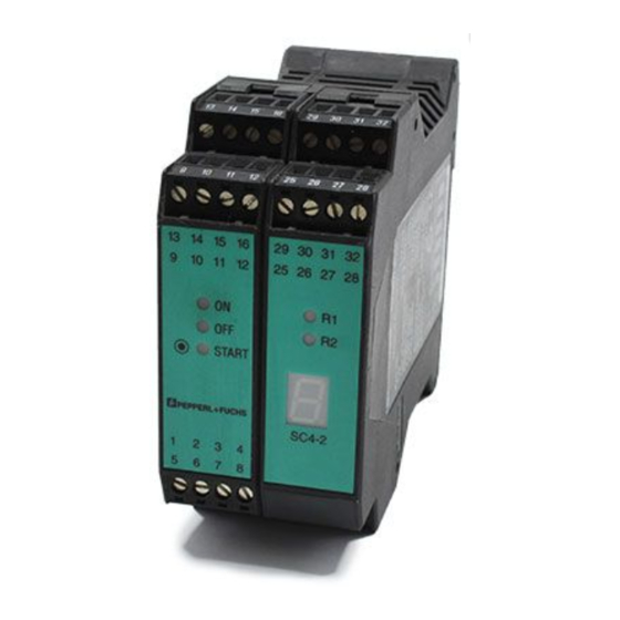
The SC4-2 control unit 16.1 Product description With its light barriers of Type SLA, the SC4-2 control unit represents a one or two-beam photoelectric protec- tive device. It consists of 2 modules, - the OSSD Module with a 2-channel relay output (OSSD) and - the light barrier module. -
Page 10: Layout
- (Optionally) a power pack (for power supply with al- SD-module Light-barrier module ternating current) START The SC4-2 is housed in a case suitable for mounting on a top hat section rail. The installation width is 45 mm. SC4-2 The following operating modes can be set as desired... - Page 11 Emitter 1 Receiver 1 Indicators Light barriers Safety core control Signal outputs Emitter 2 Receiver 2 SC4-2 OSSD- Test generation Test control 24 V DC Restart Relay monitor Restart Power supply (RI) (RM) Figure 16.2: Principle of operation of the SC4-2...
-
Page 12: Sc4-2 Connections
Relay monitor input. It should be wired in if no function is activated (see section 17.2) 24 V internal 24 V DC Supply voltage connection, protected from reverse polarity 24 V internal Normally open contact for testing or error enable Test input Table 16.1: Connections of the SC4-2 OSSD module... - Page 13 Assignment Function OSSD1.1 OSSD relay output 1 NO (normally open) OSSD1.2 OSSD2.1 OSSD relay output 2 NO OSSD2.2 Table 16.1: Connections of the SC4-2 OSSD module Terminal Assignment Function LS2-T Transmitter 2 connection LS2-T 0V LS2-R 0V Receiver 2 connection...
- Page 14 Control unit SC4-2 SC4-2 light barrier module Receiver Transmitter Conductor Conductor LS2-T transmitter BK (black) BU (blue) LS2-R receiver BU (blue) BN (brown) LS1-T transmitter BK (black) BU (blue) LS1-R receiver BU (blue) BN (brown) Table 16.3: Connection assignment of light barriers...
- Page 15 27 LS2-R 0 V Test +U Test/Reset 28 LS2-R Test 29 LS1-T Restart 30 LS1-T 0 V Restart +U Restart 31 LS1-R 0 V 32 LS1-R RM +U Supply 24V Supply 0 V + 24 V DC Figure 16.3: SC4-2 connections...
-
Page 16: Sc4-2 Displays
Control unit SC4-2 16.5 SC4-2 displays Displays for the switching state of the OSSD and status displays for indicating the operating status are loca- ted on the front plate of the two modules of the SC4-2. Display Meaning OSSD output turned off... -
Page 17: Operating Modes
Control unit SC4-2 If an error is present, the yellow LED flashes, indicating readiness for startup. The 7-segment display shows the error that has been detected (Table 16.5). Display Meaning Display Meaning Protective beams free, OSSD ON (running light) Error on one of the transmitters... - Page 18 Control unit SC4-2 When the control unit is delivered, the relay monitor (RM) is turned off and start/restart interlock (RI) is turned DIP switches Start/restart interlock (RI) Relay monitor (RM) Table 17.1: Function of the DIP switches 1 2 3 4 Figure 17.1: Position of the DIP switches...
-
Page 19: Start/Restart Interlock (Restart)
Control unit SC4-2 Operating Mode: Figure 17.2: Adhesive label for marking the operating mode 17.1 Start/restart interlock (Restart) If the protective beams are free and the start/restart interlock operating mode is activated, do not turn the OSSDs and the OSSD-ON message on. The "Restart“ output is activated and the corresponding yellow display LED lights up. - Page 20 Control unit SC4-2 The work circuit of the external switching elements must be protected by a fuse with a nominal value of maximum 60 % of the load capacity of the contacts to prevent the contacts from fusing. The external switching elements are monitored with a delay of 180 ms following the switching process.
-
Page 21: Setup And Assembly Of The Light Barriers
Control unit SC4-2 Setup and assembly of the light barriers Safety light barriers should be arranged so that the transmitters connected to the various SC4 light barrier modules cannot direct beams at the receivers of other control units. Safety light barriers must be mounted in such a manner that it is not possible to reach the hazardous area by bypassing the protective beams. - Page 22 Control unit SC4-2 To calculate the minimum distance of the photoelectric sensor from the hazardous area, please refer to the applicable requirements and standards. In accordance with EN ISO 13855, the minimum distance may be calculated by the formula: S = K · T + C Where S = the minimum safety distance in mm, i.e.
- Page 23 Control unit SC4-2 Care should be taken that reflecting objects that could result in mirroring of an obstruction are not located within the transmitter or receiver lobe (EN IEC 61496-2). For a section a > 3 m, the mini- Reflecting object outside the area covered...
-
Page 24: Installation
- Do you want the button not to be activated from within the hazardous area? 19.1 SLA light barriers Light barrier transmitters and receivers are connected according to the color of the individual conductors or the pin numbers on the light barrier module. SC4-2 light barrier module Receiver Transmitter Conductor Conductor... -
Page 25: Message Outputs
Control unit SC4-2 LS2-R receiver BU (blue) BN (brown) LS1-T transmitter BK (black) BU (blue) LS1-R receiver BU (blue) BN (brown) Table 19.1: Connection assignment of light barriers The length of the connection cable between the control unit and transmitter or receiver must not exceed 50 m. -
Page 26: Safety Outputs
Control unit SC4-2 19.3 Safety outputs The OSSD relay outputs must be protected externally with fuses. All pnp outputs are protected against short- circuit and do not require any external fuses. With an inductive load of the relay output contacts, the latter must be protected against the increased load that is thus generated by RC combination or freewheeling diodes. -
Page 27: Layout With Adjustable Mirror
Control unit SC4-2 20.2 Layout with adjustable mirror Adjustable mirrors are used for deflection away from protective beams and fields for securing them on mul- tiple sides with only one transmitter/receiver pair. Each mirror reduces the maximum detection range by a maximum of 15%. -
Page 28: Test Of Start/Restart Interlock And Startup Enable (Restart/Start)
Control unit SC4-2 20.3.2 Test of start/restart interlock and startup enable (restart/start) - Interrupt one beam and then make all beams free. - Output relays must remain blocked if there is an existing startup interlock, and the indicator light for readi- ness for startup must light up or the "Restart“... -
Page 29: 20.3.5 Principle Of Operation Of The Ossd Outputs
Control unit SC4-2 20.3.5 Principle of operation of the OSSD outputs The OSSD outputs are turned on under the following conditions: - With active startup lock: The protective beams are free and startup is enabled. - Without startup lock: The protective beams are free. -
Page 30: Troubleshooting
Control unit SC4-2 Troubleshooting Errors in the system always result in the system making a transition to the secure interlock state. The OSSDs are then turned off. Errors bring the system to a status that generates an error display. The output for readiness for startup can be used to indicate an error externally. The output switches on and off at a rate of once per second in the event of an error To acknowledge an error, the operator presses the test input for 0.05...1 s, thus executing a reset. - Page 31 Control unit SC4-2 Display Possible fault remedy LEDs for the protective beam do not light up The protective beams are not free. Make the protective beam free. Check the status of the displays on the receivers. Check whether all transmitters are lit up. Eliminate any dirt spots If necessary, readjust the transmitter and receiver.
-
Page 32: Technical Data
Control unit SC4-2 Technical data 23.1 Parameters Approvals TÜV Tests EN IEC 61496; EN ISO 13849; EN 50178; EN 55022 The specified standards refer on the respective current version of the normative documents Safety type 4 (EN IEC 61496) Performance Level... - Page 33 Control unit SC4-2 Response time 30 ms Displays OSSD status: OFF – LED red, ON – LED green "Readiness for startup" status: yellow LED Protective beam status: one yellow LED per beam Error status: 7-segment display (the "Readiness for startup" LED also flashes) Inputs (push button connec- Input resistance approx.
-
Page 34: Dimensions
22.5 mm and is comparable in its other dimen- sions to the housing of the control unit. SC4-2 Designation SC PS 120-230 VAC CPU-Print up to grating: approx. 145 23.4 Ordering information Designation SC4-2 24 VDC START SC4-2 45.2 113.6... -
Page 35: Sample Circuits For Sc4-2
Control unit SC4-2 Sample circuits for SC4-2 ready to restart (yellow) Restart 1 2 3 4 OFF (red) OSSD OFF ON (green) OSSD ON 25 LS2-T 26 LS2-T 0 V 27 LS2-R 0 V Test +U 11 Test/Reset LSS1 LSE1... - Page 36 Control unit SC4-2 ready to restart (yellow) Restart 1 2 3 4 OFF (red) OSSD OFF ON (green) OSSD ON 25 LS2-T 26 LS2-T 0 V 27 LS2-R 0 V Test +U LSS1 LSE1 Test/Reset 28 LS2-R Test 29 LS1-T...
-
Page 37: Glossary
Electrosensitve protection equipment, german: BWS External device monitoring, normally closed contact of safety components downstream in the circuit, that reports switching of the dangerous action to the SC4-2; also: Relay monitor Function reserve The distance from the receiver signal of the photoelectric detector to the lower limit of the swit-... -
Page 38: Standards
Control unit SC4-2 Standards The relevant laws and standards apply to the use of photoelectric protective devices. There are diffe- rences depending on the area of use. The following regulations are relevant within the EU and Ger- many. 26.1 Construction and equipping of protective equipment IEC 61496-1 Safety of machinery. - Page 39 Control unit SC4-2 Directive 98/37/EC, from 29.12.2009 Directive 2006/ Machinery Directive 42/EC EN ISO 12100 Safety of machinery - electrical equipment of industrial machines EN ISO 13849-1 Safety of machinery - safety relevant parts of controls- part 1: General design principles...
-
Page 40: Notes
Control unit SC4-2 Notes... - Page 41 With regard to the supply of products, the current issue of the following document is applicable: The General Terms of Delivery for Products and Services of the Electrical Industry, published by the Central Association of the Electrical Industry (Zentralverband Elektrotechnik und Elektroin- dustrie (ZVEI) e.V.) in its most recent version as well as the supplementary clause: "Expanded reservation of proprietorship"...
- Page 42 USA Headquarters Pepperl+Fuchs Inc. · Twinsburg, OH · USA E-mail: fa-info@us.pepperl-fuchs.com Asia Pacific Headquarters Pepperl+Fuchs Pte Ltd · Singapore Company Registration No. 199003130E E-mail: fa-info@sg.pepperl-fuchs.com www.pepperl-fuchs.com 119701 TDOCT-0260A 03/2012 Subject to modifications without notice • Copyright Pepperl+Fuchs • Printed in Germany...
Need help?
Do you have a question about the SC4-2 and is the answer not in the manual?
Questions and answers