Table of Contents
Advertisement
Quick Links
Advertisement
Table of Contents

Related Manuals for Pepperl+Fuchs WCS DG310


Summary of Contents for Pepperl+Fuchs WCS DG310
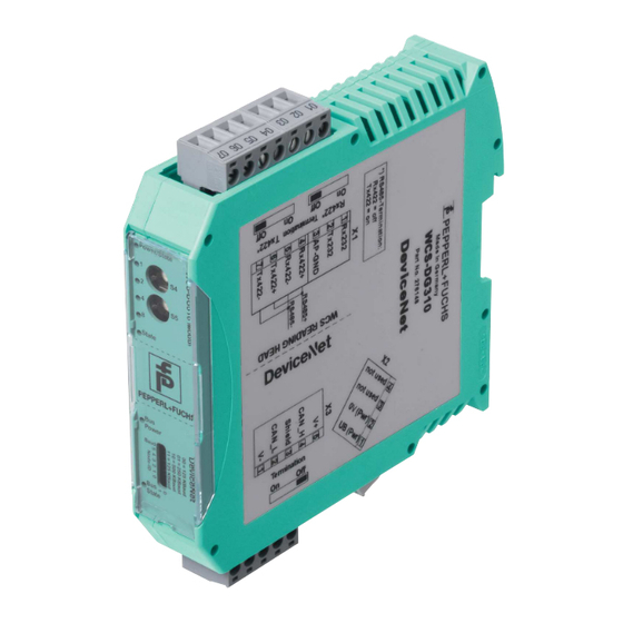
- Page 1 FACTORY AUTOMATION MANUAL WCS DG310 WCS DeviceNet Interface Module...
- Page 2 WCS DG310 With regard to the supply of products, the current issue of the following document is ap- plicable: The General Terms of Delivery for Products and Services of the Electrical Indus- try, published by the Central Association of the Electrical Industry (Zentralverband Elektrotechnik und Elektroindustrie (ZVEI) e.V.) in its most recent version as well as the...
-
Page 3: Table Of Contents
WCS DG310 Introduction................. 4 Content of this Document ..............4 Target Group, Personnel..............4 Symbols Used ..................4 Product Description ..............6 Use and Application................6 Installation................... 7 Mounting ....................7 Electrical Connection ................7 Commissioning................9 Meaning of LEDs .................. 9 Meaning of Switches................ -
Page 4: Introduction
WCS DG310 Introduction Introduction Content of this Document This document contains information required to use the product in the relevant phases of the product life cycle. This may include information on the following: Product identification Delivery, transport, and storage Mounting and installation... -
Page 5: Symbols Used
WCS DG310 Introduction Symbols Used This document contains symbols for the identification of warning messages and of informative messages. Warning Messages You will find warning messages, whenever dangers may arise from your actions. It is mandatory that you observe these warning messages for your personal safety and in order to avoid property damage. -
Page 6: Product Description
WCS DG310 Product Description Product Description Use and Application The WCS-DG310 is used as an interface between the WCS reader and the DeviceNet bus. The data between the WCS reader(s) and the WCS-DG310 is transferred via the RS 485 interface, and from the WCS-DG310 to the control panel via the DeviceNet protocol. -
Page 7: Installation
WCS DG310 Installation Installation Mounting The dimensions of the WCS-DG310 interface module are: 23 x 116 x 115 mm (W x H x D). The WCS-DG310 interface module is attached to a 35 mm wide DIN mounting rail (EN 50022- 35) with a snap-on fixing method. - Page 8 WCS DG310 Installation Terminal Designation UB (Pwr) Operating voltage interface module/ operating voltage WCS reader 0 V (Pwr) Ground interface module/ground WCS reader Table 3.2 Terminal X2 Caution! Damage to the device Connecting an alternating current can damage the device or result in it malfunctioning.
-
Page 9: Commissioning
WCS DG310 Commissioning Commissioning Meaning of LEDs Power: The "Power" LED is green: The WCS-DG310 interface module is correctly connected to the power supply. BusPower: The "Power" LED is green: The LED is connected directly to the electrically isolated supply voltage of the DeviceNet side. -
Page 10: Meaning Of Switches
WCS DG310 Commissioning ErrorNo/Select ID LED Error number A description of the fault LED8 LED4 LED2 LED1 Reserved Hardware error EEPROM error Internal memory error Fieldbus hardware error or incorrect fieldbus ID Script error Reserved Communication WCS reader, RS send buffer overflow... -
Page 11: Operating Modes
WCS DG310 Commissioning If the interface module is operated as the first or last physical device as a 422, a bus termination must also occur. By moving the "Rx 422 Termination" or " Tx 422 Termination” slide switch to "On", the integrated terminators can be activated in the Rx or Tx direction. -
Page 12: Connecting The Wcs Reader
WCS DG310 Commissioning Data exchange mode The interface module must be in data exchange mode, so that data exchange between the RS 485 side (the WCS readers) and the DeviceNet bus can occur. This mode is always active when the interface module is not in configuration or test mode. In data exchange mode, the interface module will run the installed script. -
Page 13: Connection To The Control Panel
WCS DG310 Commissioning Set baud rate (DIP switch) You can set the baud rate in DeviceNet with 2 switches on the 8-way DIP switch of the WCS- DG310. The location of the DIP switches is marked on the device label. -
Page 14: Eds Configuration File
WCS DG310 Commissioning Bit-strobe With bit-strobe access, the "Bit-strobe" command is sent from the master without any further data. The master then always receives 8 data bytes from the interface module as a response. The 8 data bytes contain the data of the WCS readers with the address 0 and 1 (2 x 4 bytes). If the WCS reader with address 1 is not connected (rotary switch S4 is in position 1), the 4 data bytes for this WCS reader are 0x00. -
Page 15: Appendix
WCS DG310 Appendix Appendix Cable Routing in the RS-485 Bus The data cable must always form an in-line connection between the first and the last node. This in-line connection must end with a terminator. The RS-485 terminators are integrated in the WCS readers and can be switched on and off with the interface module. - Page 16 WCS DG310 Appendix If two readers are connected to one interface module, there are two wiring versions: Version A: One WCS reader is located at the beginning and one WCS reader at the end of the data line. For both WCS readers, the RS-485 terminator is activated. The interface module is located between these two heads and does not have an RS-485 terminator.
- Page 17 WCS DG310 Appendix Version B: The interface module is located at the beginning of the data line; one WCS reader is located at the end of the data line. Both need the RS 485 terminator. The second WCS reader is connected to the line connection between the interface module and the first WCS reader through a short spur (length <1 m).
-
Page 18: Meaning Of F0
WCS DG310 Appendix Meaning of F0 Function number for WCS reader Send position value Send diagnosis result Diagnostic function F0=1 The WCS reader can be requested to perform a diagnosis of the photoelectrics by means of the request byte. For this purpose, the WCS reader must be located outside of the code rail. -
Page 19: Data From Wcs Reader
WCS DG310 Appendix Data from WCS Reader Meaning of A1 and A0 Reader address Read head address 0 Read head address 1 Read head address 2 Read head address 3 Function number for WCS reader F0=0 (send position value) Optical state... -
Page 20: Data Cables And Accessories
WCS DG310 Appendix Data Cables and Accessories RS485 data cable For the RS 485 data transfer path, a 4-wire, shielded, twisted pair data cable must be used. One wire pair is used for the supply voltage, and one pair for the RS 485 data connection. The maximum length of the cable depends on the data transfer capacity of the data cable (core- core) and on the cross section of the cables for power supply of the WCS readers. - Page 21 WCS DG310 Appendix WCS-DCS / WCS-DCF data cables There are 2 types of data cable available: . WCS-DCS for stationary cable routing . WCS-DCF for trailing cable and drag chain installations. The data cables are twisted pair, and have a tinned copper braided shield. The braided shield surrounds all wire pairs.
- Page 22 Twinsburg, Ohio 44087 · USA Tel. +1 330 4253555 E-mail: sales@us.pepperl-fuchs.com Asia Pacific Headquarters Pepperl+Fuchs Pte Ltd. Company Registration No. 199003130E Singapore 139942 Tel. +65 67799091 E-mail: sales@sg.pepperl-fuchs.com www.pepperl-fuchs.com Subject to modifications / TDOCT5812_ENG Copyright PEPPERL+FUCHS • Printed in Germany 12/2017...
Need help?
Do you have a question about the WCS DG310 and is the answer not in the manual?
Questions and answers