Advertisement
Quick Links
ORIGINAL BETRIEBSANL EITUNG
Bestimmung
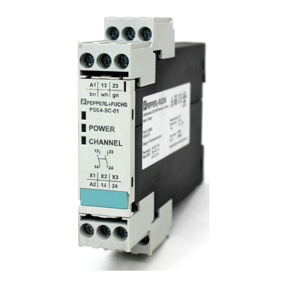
Die Auswerteeinheit PSE4-SC-01 wertet das Signal von
einer P+F PSE4 Sicherheitsschaltleiste aus. Die Auswerte-
einheit ist für den Einbau in einen Schaltschrank (IP54)
vorgesehen. Die Befestigung erfolgt auf einer Normschiene.
Mit der Betätigung einer Schaltleiste öffnet der Sicherheits-
kontakt der Auswerteeinheit. Die Auswerteeinheit erfüllt
die Anforderungen der EN ISO 13849-1:2015 Steuerungs-
kategorie 4. Die Auswerteeinheit darf nur mit einer Sen-
der-/Empfängereinheit PSE4-SL-XX
Sicherheitsbestimmungen
Vor jeder Installation oder Wartung ist diese Betriebsan-
-
leitung und die Montageanleitung vollständig zu lesen.
Alle Tätigkeiten der Installation, Inbetriebnahme und
-
Wartung sind von elektrotechnisch erfahrenem Per-
sonal vorzunehmen
Das Sicherheitsschaltgerät darf nur von Personen instal-
-
liert und in Betrieb genommen werden, die mit dieser Be-
dienungsanleitung, den geltenden VDE-Vorschriften, den
Vorschriften über Arbeitssicherheit und Unfallverhütung
sowie den örtlichen Vorschriften (Schutzmaßnahmen)
vertraut sind. Die Gesamtsicherheit von Maschine und
Schutzeinrichtung ist von der Zuverlässigkeit der da-
zwischenliegenden Schnittstelle abhängig.
Erschütterungen größer als 5 g/33 Hz (VDE 0160) sind
-
zu vermeiden.
Austausch und Verwendung von nicht vom Hersteller
-
zugelassenen Komponenten können die Funktion der
Einrichtung beeinträchtigen. Durch Öffnen des Gehäuses
oder eigenmächtige Umbauten erlischt jegliche Gewähr-
leistung.
Das Gerät muss in einem Schaltschrank (IP54) montiert
-
werden; Staub oder Feuchtigkeit können sonst zu Beein-
trächtigungen der Funktion führen.
Auf ausreichende Schutzbeschaltung der Ausgangs-
-
kontakte bei kapazitiven und induktiven Lasten ist zu
achten.
Die Freigabepfade sind nach DIN VDE 0110 Teil 1 sicher
-
getrennt bis 300 V.
1
XX steht stellvertretend für nachfolgende Zahlen zur Unterscheidung von
Kabellängen
Ausgabestand/Issue date 2019-04-15
Destination and use
The PSE4-SC-01evaluation unit evaluates the signal from
one P+F PSE4 safety edge. The evaluation unit is in-
tended for fitting inside a control panel (IP54). It is fixed by
fitting on a standard rail. When the safety edge is actu-
ated, the safety contact of the evaluation unit opens. The
evaluation unit fulfils the requirements of EN ISO 13849-
1:2015 to Control Category 4. It may only be operated
with the PSE4-SL-XX
1
betrieben werden.
Safety regulations
-
-
-
-
-
-
-
-
2
TECHNI CAL INSTRUCTION
2
sensor set.
Do read this technical instruction and the mounting
instruction carefully before installation or service.
Installation and Service should be conducted through
experienced persons only.
The unit should be installed and operated by persons,
who are familiar with these instructions and the current
regulations for safety at work and accident prevention.
Follow local regulations especially as regards preven-
tative measures. Safety level of machine and safety
equipment depends on reliability of the used interface.
Avoid mechanical vibrations greater than 5 g/33 Hz both
when transporting and in operation.
Replacement and use of components, which are not
certified by the producer may cause safety risk. Any
guarantee is void following opening of the housing or un-
authorised modifications.
The unit should be panel mounted in an enclosure rated
at IP54 or better, otherwise dampness or dust could lead
to function impairment.
Adequate fuse protection must be provided on all output
contacts with capacitive and inductive loads.
The safety contacts are separated safely regarding to
DIN VDE 0110 part 1 up to 300 V.
XX indicates numbers to differentiate various cable lengths
PSE4-SC-01
Seite/Page 1/8
Advertisement

Related Manuals for Pepperl+Fuchs PSE4-SC-01


Summary of Contents for Pepperl+Fuchs PSE4-SC-01
- Page 1 ORIGINAL BETRIEBSANL EITUNG TECHNI CAL INSTRUCTION Bestimmung Destination and use Die Auswerteeinheit PSE4-SC-01 wertet das Signal von The PSE4-SC-01evaluation unit evaluates the signal from einer P+F PSE4 Sicherheitsschaltleiste aus. Die Auswerte- one P+F PSE4 safety edge. The evaluation unit is in- einheit ist für den Einbau in einen Schaltschrank (IP54)
-
Page 2: Installation
PSE4-SC-01 ORIGINAL BETRIEBSANL EITUNG TECHNI CAL INSTRUCTION Anwendungsbeispiele Application examples Geeignete Anwendungen Suitable applications Absicherung der bewegten Schließkante von Maschi- Safety door on a machine, in order to stop the move- nenschutztüren mit dem Ziel die Bewegung zu stoppen. ment. - Page 3 14/24 unterbrochen. Ist der Lichtweg start/reset switch is used for a new start. wieder frei, erfolgt ein erneuter Start durch Betätigung des The safety output (14/24) of the control unit PSE4-SC-01 Reset-Tasters. may remain in an open position if the safety edge re- Der Sicherheitsausgang (14/24) des Auswertegeräts...
- Page 4 Die nachfolgenden Sicherheitskenngrößen gelten für die The safety properties listed below are valid for the Kombination aus PSE4-SL-XX und PSE4-SC-01. Sie combination of PSE4-SL-XX and PSE4-SC-01. They do beinhalten keine Angaben des Gummihohlprofils. not include values of the rubber profile.
- Page 5 PSE4-SC-01 ORIGINAL BETRIEBSANL EITUNG TECHNI CAL INSTRUCTION Elektrische technische Daten Electrical technical data Versorgungsspannung 24 V DC (+20 % / -10 %) Power supply 24 V DC (+20 % / -10 %) Leistungsaufnahme < 4 W Power consumption < 4 W Absicherung 1 A träge...
- Page 6 PSE4-SC-01 ORIGINAL BETRIEBSANL EITUNG TECHNI CAL INSTRUCTION Zeichnung Drawing PSE4-SC-01 Funktionsschaltbild Connection diagram Seite/Page 6/8 Ausgabestand/Issue date 2019-04-15...
- Page 7 Leads interrupted or short circuit; structed; Check leads; profile damaged Test OSE without profile; Terminal assignment wrong; Check terminal assignment; Control unit defective Replace control unit PSE4-SC-01 LED Ohne Funktion (immer aus) PSE4-SC-01 LED No Function (always off) Ausgabestand/Issue date 2019-04-15 Seite/Page 7/8...
- Page 8 PSE4-SC-01 ORIGINAL BETRIEBSANL EITUNG TECHNI CAL INSTRUCTION Maschine / Bauvorhaben Machine / Building project ______________________________________________ ______________________________________________ ______________________________________________ ______________________________________________ ______________________________________________ ______________________________________________ ______________________________________________ ______________________________________________ Eingebaute Komponenten Used Components Bezeichnung / Designation Signalauswertung Control unit Profil Signalgeber Rubber-Profile Sender Transmitter Empfänger Receiver AL-Montageleiste...
Need help?
Do you have a question about the PSE4-SC-01 and is the answer not in the manual?
Questions and answers