
Related Manuals for Pepperl+Fuchs 7500 Series


Summary of Contents for Pepperl+Fuchs 7500 Series
- Page 1 Manual 7500 Series Bebco EPS 7500 Series Type Z and ® Ex pzc Purge and Pressurization System...
- Page 2 With regard to the supply of products, the current issue of the following document is applicable: The General Terms of Delivery for Products and Services of the Electrical Industry, published by the Central Association of the Electrical Industry (Zentralverband Elektrotechnik und Elektroindustrie (ZVEI) e.V.) in its most recent version as well as the supplementary clause: "Expanded reservation of proprietorship."...
-
Page 3: Table Of Contents
2.1.4 Pertinent Laws, Standards, Directives, and Further Documentation ........8 2.1.5 Declaration of Conformity ......................8 General Information on Purge and Pressurization ..............9 Conditions of Safe Use ......................9 7500 Series System Components ..................10 Control Unit ..........................10 4.1.1 Technical Data—Control Unit ....................11 4.1.2 Terminal Connection Data ....................13 4.1.3 Electrical Connections......................13... - Page 4 7500 Series Manual Menu Structure ........................37 Purge Programming Settings ....................38 6.5.1 Program 1 ...........................38 6.5.2 Program 2 ...........................39 6.5.3 Program 3 ...........................40 6.5.4 Program 4 ...........................40 6.5.5 Program 5 ...........................41 6.5.6 Sequence of Events for All Programs ..................42 Purging Timer ........................42 Minimum Enclosure Pressure “P1”...
- Page 5 7500 Series Manual This page left blank intentionally.
-
Page 6: Preface
Information on This Manual Knowledge of the basic safety regulations and additional training and experience in the area of explosion protection are essential for the safe handling and failure-free operation of the 7500 series purge and pressurization system. These operating instructions contain important data and information to ensure the safe use of the 7500 system in hazardous areas and to meet the requirements of Directive 2014/34/EU. -
Page 7: Safety
7500 Series Manual Safety Introduction 2.1.1 Contents This document contains information that you need to use your product throughout the applicable stages of the product life cycle. These can include the following: Product identification „ Delivery, transport, and storage „... -
Page 8: Symbols Used
7500 Series Manual 2.1.3 Symbols Used This document contains symbols for the identification of warning messages and of informative messages. Warning Messages You will find warning messages in instances where danger may arise from your actions. You must observe these warning messages for your personal safety and to avoid property damage. Depending on the risk... -
Page 9: General Information On Purge And Pressurization
Do not use or install in high charge- areas. See IEC60079-32-1 for more information. 4. When the 7500 series purge and pressurization system is mounted to an enclosure, the complete installation shall be evaluated to the appropriate standards and regulations that are applicable for the final installation location. -
Page 10: 7500 Series System Components
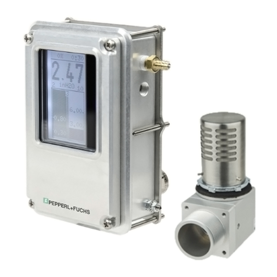
7500 Series System Components The 7500 series system consists of a control unit, an enclosure protection vent, and manual or automatic manifold. The control unit has a touch screen display that is menu driven and will easily guide the user in selecting pre-programmed and user-selected variables. -
Page 11: Technical Data-Control Unit
7500 Series Manual 4.1.1 Technical Data—Control Unit General specifications Equipment architecture max. enclosure size 450 ft (12.7 m Operating mode fully automatic (FA) Series 7500 Hazardous environment gas or dust Supply Rated voltage U 20 ... 30 V DC at 0.1 A 90 ... -
Page 12: Terminal Connection Data
7500 Series Manual Vibration resistance 5 ... 100 Hz , 1 g, 12 m/s , all axes Impact resistance 30 g, 11 ms, all axes Mechanical specifications Connection type electrical: 2 x 1/2 inch NPTF (open from factory) 1 x M12 opening (plugged from factory) -
Page 13: Electrical Connections
7500 Series Manual 4.1.3 Wiring Requirements and Electrical Connections Wiring Requirements 1. All applicable local and national wiring codes must be followed when wiring the system. See IEC 60079-14 for more information. 2. The power supply to this device shall have a separate disconnect. If placed in the hazardous area, it shall be rated for the area in which it is being installed. -
Page 14: Dimensions-Control Unit
7500 Series Manual 4.1.4 Dimensions—Control Unit M4 x .7 R4.5 1/2-14 17.5 22 M12 x 1.5 1. High-pressure port 1/8-27 NPT 2. Low-pressure port 1/8-27 NPT 3. Protective earth stud, torque 12 in lb (1.35 Nm) 4.1.5 Panel Cut-Out Dimensions 137 ±... -
Page 15: Pressure Kit
7500 Series Manual 4.1.6 Pressure Kit The included pressure kit contains the following components: Bulkhead fitting O-ring Tubing Tubing inserts Straight connector Sintered element for bulkhead fitting 4.1.7 Torque Requirements Hardware Torque Main lid 12 in lb (1.36 Nm). M4 screws for mounting bracket 12 in lb (1.36Nm). -
Page 16: Dimensions-7500-Mtd* External/Panel Mount Systems
7500 Series Manual 4.1.8 Dimensions—7500-MTD-* External/Panel Mount Systems 7500-MTD-BXRW-01 Rectangular External Mount with Control Unit and Manifold... - Page 17 7500 Series Manual 7500-MTD-PMRW-01 Rectangular Panel Mount with Control Unit and Manifold...
- Page 18 7500 Series Manual 7500-MTD-BXSW-01 Square External Mount with Control Unit and Manifold...
- Page 19 7500 Series Manual 7500-MTD-PMSW-01 Square Panel Mount with Control Unit and Manifold...
-
Page 20: External/Panel Mount Illustration
7500 Series Manual 4.1.9 External/Panel Mounting Illustration... -
Page 21: Epv-7500 Vents
7500 Series Manual EPV-7500 Vents EPV-7500 vents work with the 7500 control unit and manifold to provide a functional, certifiable purge and pressurization system for enclosures. As required by all pressurized enclosure systems, the EPV-7500 vent functions as a pressure relief device and allows the purge gas to exit the enclosure, yet provides a seal when the enclosure is pressurized and operating. - Page 22 7500 Series Manual Conformity Degree of protection EN 60529 Shock resistance EN 60068-2 Ambient conditions Ambient temperature -40 ... 70 °C (-40 ... 158 °F) (AA and SS versions) -20 ... 60 °C (-4 ... 140 °F) (PY versions) Storage temperature -40 ...
-
Page 23: Flow Rate Curves
7500 Series Manual 4.2.2 Flow Rate Curves The enclosure pressure vs. flow rate curves below represent the EPV-7500..-01, 02, 03, and 04 vents. This corresponds to the enclosure pressure and is independent of the valve used, provided the valve can deliver the flow rate that is required. - Page 24 7500 Series Manual EPV-7500-...-02 Vent Flow vs. Enclosure Pressure Inches of water mbar 2.15 5.36 2.35 5.85 2.65 6.60 2.85 7.10 3.15 7.84 3.35 8.34 3.65 9.09 4.25 10.58 4.75 11.82 5.25 13.07 EPV-7500-...-03 Vent Flow vs. Enclosure Pressure Inches of water mbar 2.00...
-
Page 25: Dimensions-Epv-7500 Vents
7500 Series Manual 4.2.3 Dimensions—EPV-7500 Vents EPV-7500-...-01/02/03 1 1/2 NPS thread (3) Hex key 0.050" (included) 23.4 Exhaust port Inlet port 49.5 57.2 73.2 98.5 EPV-7500-PY-04 55.0 mm (2.15") 28.0 mm (1.10") 25.0 mm (1.00") 41.0 mm (1.60") 9.0 mm (0.35") -
Page 26: 7500-Man-Mv-01 Manual Manifold
The ball valve has a handle for easy actuation. To provide security and prevent tampering, the needle valve requires a slot-head screwdriver to set the enclosure pressure. Note! The 7500-MAN-MV-01 manifold can be used with 7500 series or 5500 series purge and pressurization systems. Note 4.3.1... -
Page 27: Dimensions-7500-Man-Mv-01
7500 Series Manual 4.3.2 Dimensions—7500-MAN-MV-01 Manifold 18.25 1/2-14 NPT 32.5 Needle valve 5.5 ø thru-hole 41.5 55 20 17.5 17.5 17.5 Ball valve 42.5 closed Ball valve open... -
Page 28: Automatic Manifolds
7500 Series Manual Automatic Manifolds Pepperl+Fuchs 5500 series automatic manifolds can be used with the 7500 system because the area classification is the same for both systems. The 7500 system is certified with the control unit and the EPV- 7500 vents and does not include the manifolds. The 5500 manifolds have their own certification from the manufacturers. -
Page 29: Technical Data-5500 Manifolds
7500 Series Manual Tubing kit included mounting hardware included 5500 manifolds include the solenoid and manual needle valve 3/8 inch compression ferrule fittings for inlet and outlet protective gas source 3/8 inch compression ferrule bulkhead fitting that attaches to enclosure—for protective gas to inside... - Page 30 7500 Series Manual Pneumatic parameters 5500-MAN-CDUL (only 60 Hz for AC version) Protective gas supply 5 μm filtered air or inert gas Pressure requirement 20 psi (1.4 bar) to 120 psi (8.2 bar) Purge flow rate (solenoid valves) Cv (flow coefficient) = 1.4 Pressurization flow (needle valve) Cv (flow coefficient) = 0.24...
-
Page 31: Dimensions-5500 Manifolds
7500 Series Manual 4.4.2 Dimensions—5500 Manifolds 5500-MAN-CDUL 70.7 41.4 12.7 82.3 ø6.5 (4x) 1/2"-14 NPT 73.2 50.3 5500-MAN-EX01 24.1 14.6 3/8" NPT (2x) 12.7 22.2 38.1 14.8 53.3 22.2 1/4-20UNC 8 (4x) 1/4-20UNC 9.5 (4x) - Page 32 7500 Series Manual 5500-MAN-CD01 24.1 14.6 3/8" NPT (2x) 56.6 12.7 22.2 38.1 14.8 53.3 22.2 1/4-20UNC 9.5 (4x) 1/4-20UNC 0.375 (4x)
-
Page 33: Installation And Operation
7500 Series Manual Installation and Operation The 7500 series control unit, vent, and manifold can be universally mounted to the customer enclosure. The 7500-01-AA-STD-UNV-PNO is panel-mounted to the enclosure. An included bracket provides a Type 4X / IPX6 mounting. The7500-MTD-PM... includes the 7500-01... control unit and 7500-MAN-MV-01 mounted onto a flat panel that is then panel-mounted to the enclosure with the included bracket and gasket for a Type 4X / IPX6 mounting. -
Page 34: Setting Up The System
1. Ensure that the system meets all electrical, mechanical, and pneumatic connections before operation. Refer to this manual and standards for explanation of requirements. 2. Apply power to the 7500 series system. 3. Program the 7500 system using the user-interface display on the front of the 7500 control unit. See chapter 6 for instructions. -
Page 35: Programming
7500 Series Manual Programming Use the touch screen on the front of the 7500 control unit to program the system: Portrait View Landscape View Purging time: % complete / Time left Purging time: % complete / Time left Enclosure Pressure... -
Page 36: Led Indication
7500 Series Manual LED Indication LED Color Description Green Contact K1 is energized Amber Contact K2 is energized P/SV Blue/amber Blue: safe pressure Amber: valve on Default Settings The following table shows all the possible parameters and their default values:... -
Page 37: Menu Structure
7500 Series Manual Menu Structure MENU STRUCTURE LEAKAGE Power On HYST PROGRAM 5 sec. PASSWORD SHUT-OFF DELAY BYPASS PURGE PROGRAM left UNITS Purge Time CHANGE ENCLOSUR PASSWORD PRESS P1 RESTORE ENCLOSUR At any time during DEFAULT PRESS P2 purge settings... -
Page 38: Purge Programming Settings
7500 Series Manual Purge Programming Settings There are 5 program selections for system operation. Programs 1 through 4 are for hazardous gas environments and require purging. The fifth program is for hazardous dust environments that require cleaning the enclosure, then pressurizing. -
Page 39: Program 2
7500 Series Manual Warning! If K1 is used to energize power to the enclosure, K1 will remain energized if pressure is below P1 during system operation. An alarm is required and must be located such that an operator will be notified of the alarm. -
Page 40: Program 3
7500 Series Manual 6.5.3 Program 3 Program 3 is used in hazardous gas atmospheres. Pre-Purge The purge valve (SV) is energized when enclosure pressure is greater than P1. If enclosure pressure goes above P4 during purging, the SV will shut off but will energize when below P4. -
Page 41: Program 5
7500 Series Manual Operation Mode After the purge timer counts down, SV shuts off and K1 is energized. If enclosure pressure drops below P3, the SV is energized and will stay energized for the value of HYST (%, leakage compensation). If HYST is set to 0, leakage compensation is turned off. However, Program 4 is usually used when a continuous purging through the enclosure is required during operation mode. -
Page 42: Sequence Of Events For All Programs
7500 Series Manual 6.5.6 Sequence of Events for All Programs Program Purging P<P1 P1<P<P2 P2<P<P3 P3<P<P4 P>P4 Clean activates above P1 After purging P<P1 P1<P<P2 P2<P<P3 P3<P<P4 P<P4 Note! Shutdown timer and bypass affect the status of K1 and SV. See the explanation for each to determine effects on K1 and SV. -
Page 43: Minimum Enclosure Pressure "P1
7500 Series Manual Minimum Enclosure Pressure “P1” In accordance with the applicable standards and tolerances on the 7500 pressure sensor, the minimum operating pressures are as follows: Gas environments: 0.25 in wc (0.63 mbar) Dust environments: 0.65 in wc (1.63 mbar) When enclosure pressure drops below P1 during operation mode, the power has to be interrupted. - Page 44 7500 Series Manual Leakage Compensation Hysteresis “HYST” In operation mode, there may be excess leakage of pressure from the enclosure because a seal or gasket has caused a drop in regulated line pressure (protective gas source). The leakage compensation option allows the SV to turn on to compensate for these unintentional leakages.
-
Page 45: Programming K2
7500 Series Manual 6.11 Programming K2 The K2 contact output can be programmed for various settings that are chosen by the user. For Type Z and Ex pz systems, power to the pressurized enclosure can remain on if pressure goes below the minimum allowed pressure, but an audible and/or visual alarm must be generated to notify the operator of a problem. - Page 46 7500 Series Manual...
-
Page 47: Shutdown Timer For K1
7500 Series Manual 6.12 Shutdown Timer for K1 The shutdown timer is used in the operation mode and allows K1 to remain on for the duration of this setting when enclosure pressure drops below the minimum setting of P1. If the pressure goes above P1 during the countdown, the timer is reset. -
Page 48: Bypass
7500 Series Manual 6.13 Bypass The Bypass mode allows power to the enclosure to be energized when the enclosure pressure is below the minimum pressure P1. This can be useful in commissioning the enclosure or working on the enclosure when it is open. -
Page 49: Change Password
7500 Series Manual 6.15 Change Password To change the existing password, use the UP and DOWN buttons for each digit. Enter 4 digits. To cancel without saving a new password, press RESET. The existing password will still be valid. Note! There is no confirmation of key strokes when changing the password. -
Page 50: Determining Purging Time
7500 Series Manual Determining Purging Time To make sure the enclosure is safe from the hazardous atmosphere, the inside of the enclosure has to be free of the hazardous atmosphere and pressurized before the equipment inside can be powered. The first step in this process is to get rid of the hazardous atmosphere within the enclosure. -
Page 51: User Parameter Setting Sheet
7500 Series Manual User Parameter Setting Sheet Display Description User Settings PASSWORD / SET Password PURGE / PROGRAM Program 1-5 PURGE / TIME Time required for purging ENCLOSUR / PRESS P1 Shutdown pressure P1 ENCLOSUR / PRESS P2 Alarm/signal pressure P2... -
Page 52: Type Codes
7500 Series Manual Type Codes 7500 Control Unit Standard control unit 7500-MTD-* Panel/External Mount System EPV-7500 Vents... - Page 53 7500 Series Manual 7500-MAN-MV-01 Manifold 5500 series manifolds...
-
Page 54: Certifications
Ex-relevant 7500 Series Manual Certifications 10.1 Applied Standards Note! See the certificates and/or the Declaration of Conformity for details on specific editions of the below-listed Note standards. IECEx and ATEX: IEC/EN 60079-0 Layout for IEC/EN 60079-2 IEC/EN 60079-7 7500 Cert/Model... - Page 55 7500 BXRW Model 7500 PMSW Model 7500 Series Manual 1.50” 1.50” Control Unit and Manual Manifold, 7500-MTD-... 68307 Mannheim, Germany / www.pepperl-fuchs.com 68307 Mannheim, Germany / www.pepperl-fuchs.com Model: 7500-MTD-BXRW-01 Model: 7500-MTD-PMSW-01 Type Z / Ex pzc Type Z / Ex pzc...
-
Page 56: Maintenance And Repair
When operating the 7500 system in conjunction with a hazardous area, do not modify the system. If there is a defect, the product may need to be replaced. Repairs can only be performed by a Pepperl+Fuchs specialist who is trained and authorized to repair the defect. - Page 57 7500 Series Manual This page left blank intentionally.
- Page 58 7500 Series Manual This page left blank intentionally.
- Page 59 7500 Series Manual This page left blank intentionally.
- Page 60 Pepperl+Fuchs Quality Download our latest policy here: www.pepperl-fuchs.com/quality www.pepperl-fuchs.com Subject to modifications © Pepperl+Fuchs · Printed in USA · TDOCT-B1V3_ENG 06/18...
Need help?
Do you have a question about the 7500 Series and is the answer not in the manual?
Questions and answers