Table of Contents
Advertisement
Quick Links
Advertisement
Table of Contents

Subscribe to Our Youtube Channel
Related Manuals for Grundig GD-TI-AT30105K


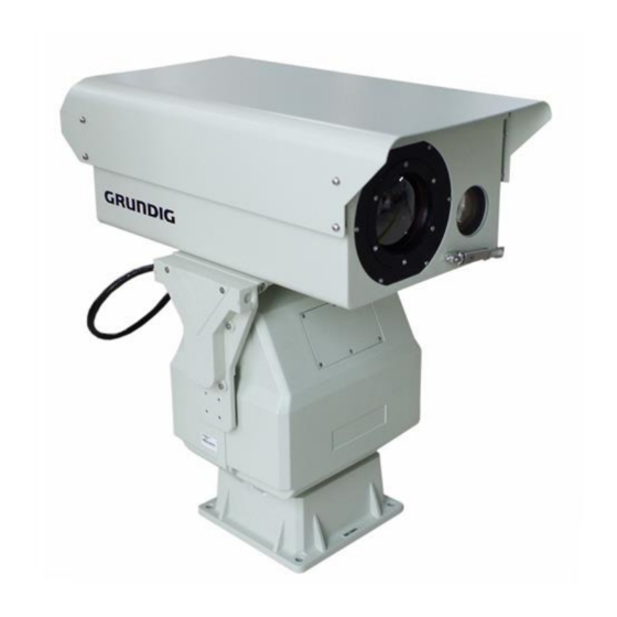
Summary of Contents for Grundig GD-TI-AT30105K
-
Page 2: Table Of Contents
Contents Product Overview ............................. 4 Log in and Log out ..........................5 2.1 Logging in to the Web Interface ....................5 2.2 Logout ..............................6 2.3 Introduction of the Main Web Interface .................. 6 Preview ................................. 7 3.1 Interface Description ........................7 3.3 PTZ Control ............................ - Page 3 6.3 Audio and Video Configuration ....................37 6.3.1 Encoding Settings ......................37 6.3.2 Imagine Settings ......................... 40 6.3.3 Video Output ........................57 6.3.4 AR ............................. 58 6.4 Alarm Management ..........................59 6.4.1 Intelligent Analysis ......................59 6.4.2 Video Blocking Alarm ....................... 77 6.5 Record Management ..........................
-
Page 4: Product Overview
1. Product Overview The user’s PC can access the IP camera through a router or switch. Before accessing the IP camera through the network, first you need to obtain its IP address. The user can search for the IP address of the network camera through the quick configuration tool. The following table shows the default parameters of different devices. -
Page 5: Log In And Log Out
2. Log in and Log out After logging in to the WEB interface of the device through a browser, you can perform operations such as preview, playback etc. 2.1 Logging in to the Web Interface The following takes IE as an example to describe the login procedures. Connecting camera to the computer, enter the camera IP address browser address bar to log in. -
Page 6: Logout
2.2 Logout When entering the main interface of the network camera, you can click " " in the upper right corner to safely exit the system. 2.3 Introduction of the Main Web Interface The live view window is displayed when you are logged in to the Web interface. The following shows an example. -
Page 7: Preview
3. Preview 3.1 Interface Description This area include: Live View windows, Live View Toolbar, PTZ Control and PTZ Functions. Figure 3-1 Preview 3.2 Shortcut Function Area Use of common functions, including screen split screen switching, primary and secondary stream switching, picture capture, video recording, focus once, manual correction, background correction, laser ranging, 3D positioning. - Page 8 Sub stream To display low-definition images Multi-screen switch Support switch for single screen and four screens Laser Range finder Click this button to trigger the laser range finder. The distance is displayed on the video. Start/stop 3D positioning Click and hold the mouse button, and then drag from top down (draw a rectangle) to specify an area.
-
Page 9: Ptz Control
3.3 PTZ Control PTZ control functions, including lens doubling, focusing, PTZ direction control, etc Button Description Control the direction of the PTZ camera and release the control. Adjust the rotating speed of the PT Adjust the focus speed of the Camera Adjust camera zoom. -
Page 10: Ptz Functions
Notes: Focusing speed currently only applies to thermal imaging, not visible light. 3.4 PTZ Functions Common functions of PTZ, including Preset, Horizontal scanning, Cruise scan, etc. 3.4.1 Setting Presets & Patrols Preset On the Preset tab, you can manage presets to the PTZ camera. The preset includes the position parameters such as the horizontal Angle, pitch Angle and focal length of the equipment lens. -
Page 11: Horizontal Scan
Step 3. Click The Settings button to add an existing preset bit and set the residence time. Step 4. Click “Start” The equipment start. Click the "paused" button to pause the cruise. Click the "Stop" button or directly control the direction to stop the cruise; Click the "Delete" button to delete the Patrol. - Page 12 on the thermal imaging video. Select "Off" and the wiper stops. After selecting "Automatic", the equipment with intelligent wiper module will trigger the wiper to work when water flows through the sensitive component quickly, and the sensitive component will not detect water flow for a period of time after the wiper stops.
-
Page 13: Video Playback
4. Video playback Currently, only SD card remote playback is supported. Local video playback is not supported. Click the Playback TAB. The Playback page is displayed. The playback screen includes the progress bar, playback control bar, and video search bar. (1) Progress bar: Displays the video type and time period. - Page 14 Note: When using SD card to store video, please make sure there is a memory card in the device. The SD card recording of single IP dual optical device can only play back one channel at the same time.
-
Page 15: Picture
5. Picture Set the alarm linkage mode to capture. When an alarm is triggered, the camera captures a picture and saves the picture in the SD card. On the Picture page, select the search time and type, and tap “Search” to search for captured images stored in the SD card. -
Page 16: Configuration Parameters
6. Configuration Parameters 6.1. System management 6.1.1 Basic Settings 6.1.1.1 Basic Information Set the device name, system language, video file saving path, and video file saving duration, as shown in Figure 6-1. For details about the parameters, see Table 6-1. Parameter Description System language... - Page 17 6.1.1.2 Time Settings Set the date and time format, time zone, system time, enable daylight saving time (DST) or configure the NTP server. For details about the parameters, see table 6-2 Table 6-2 Time parameters parameter Description Parameter Description Timezone Set the timezone where the device located Equipment time Current time of the device...
- Page 18 Note: Anyway, different devices buy different types of built-in sensors, depending on the device. Temperature Humidity Sensor Displays internal temperature and humidity data of the device in real time. Electronic compass A device with an electronic compass built in to obtain the azimuth of the device's position. Before use, the electronic compass should be corrected and the magnetic deflection Angle should be set.
- Page 19 (When the calibration fails, the pitch and level will always display 0, at this time, you need to clear the calibration and then re-calibrate) Set magnetic declination: Enter the local magnetic discrimination Angle in "Electronic compass Set Magnetic Discrimination Angle", click "Electronic compass set magnetic Discrimination Angle" to complete the setting, click "Electronic compass read magnetic Discrimination Angle", the displayed value is consistent with the set value, the setting is successful.
- Page 20 respectively. Click on to power on and click on to power off. Power control setting interface After the cooling thermal image is enabled, there will be startup progress prompt, as shown below: Cooling start interface During the cooling startup process, the startup should be completed when the temperature gradually decreases to 84K...
-
Page 21: Serial Port Configurations
6.1.2 Serial port Configurations RS485/RS422 This section describes how to set RS485/RS422 parameters, including console protocol, address, baud rate, data bit, stop bit, and parity. After the Settings are complete, you can operate the device through the panniers For details about the parameters, see Table 6-3: Table 6-3 Parameter description of the RS485/RS422 interface Parameters Description... - Page 22 Stop bit By default, 1 Check bit By default, None Note: This parameter has been configured before the device is delivered. Do not change it at will. If the parameter is incorrectly set, data cannot be sent back or controlled. (2) RS232 Set the parameters of RS232, used for auto-focus debugging, and set the transparent channel.
-
Page 23: User Settings
External output; Core transmission/n Visible-light integrated machine control 6.1.3 User settings Manage system users. You can add users, delete users, and modify user information. System users include admin, WEB user, and ONVIF user. User management functions, including adding, deleting, and modifying user information, are implemented only when users have user management rights. - Page 24 Example Add a web login user Table 6-5 describes the user parameters. Parameters Descriptions User type There are two types: operator and administrator. User name The name is used to uniquely identify the user. It cannot be the same as an existing user name.
- Page 25 After adding a user, click the "Delete" button to delete the user. Click the "Modify" button to modify the user parameters. (2) ONVIF user login You can add ONVIF users, delete ONVIF users, or modify ONVIF user passwords. After clicking the "Add" button, the "Add User" dialog box pops up. Follow the prompts, select the user type, enter the user name and password, and click the "Save"...
-
Page 26: Security Management
(3) Online user login The information about the current login user is displayed, including the login type, user name, user type, login time, and login IP address. (4) User disabled The disabled user cannot log in to the network camera. After selecting a user, select "Whether to disable"... -
Page 27: System Maintenance
Chart 6-15 User has been Disabled 6.1.5 System maintenance 6.1.5.1 System maintenance It is used to upgrade and maintain the Thermal imaging network program. Click the "Browse" button, select the upgrade file, and click the "Start System Upgrade" button. During the upgrade, the device cannot be powered off. After the upgrade is completed, the device automatically restarts. - Page 28 Thermal imaging movement maintenance Click the "Browse" button, select the upgrade file, and click "Start to upgrade the movement". During the upgrade, the device cannot be powered off. After the upgrade is completed, the movement will automatically restart. Click "Restart Movement" to manually restart the movement individually.
-
Page 29: System Log
6.1.6 System log View system logs, as shown in Figure 6-19 (1) Dynamic Log Viewer Select the log type. The log type can be all, normal, alarm, and exception. Click "Refresh" button to display the latest system logs. (2) Log download Click Download Log to download the log file in TXT format to the local PC. - Page 30 Chart 6-20 IP Setting Diagram 6-7 IP Setting Parameter description Parameter Description Host Name The Host Name of the devices Network card Select the network card to be configured, the default is wired. Mode Static Address Enter the IP address, subnet mask, and default gateway address.
-
Page 31: Onvif
camera is delivered. If a DHCP server is deployed in the network, the camera can automatically obtain an IP address from the DHCP server. MAC Address The MAC Address of the devices IP type IPv4 or IPv6 IP address Device’s Static IP Submask Usually 255.255.255.0 Gateway... -
Page 32: Gb28181
6.2.3 GB28181 The device supports access to a server that complies with the national standard 28181 protocol. After the connection is successful, the device can be used for real-time monitoring, alarm control, and other operations through the server. The parameter setting items on this page should be in accordance with the information provided by the platform during actual use. -
Page 33: Advanced Settings
SIP domain name 28181 Server platform domain name number, the default is 3402000000. SIP Server IP 28181 Server IP address, for example, 192.168.1.20. SIP Server Port 28181 Server port number. The default value is 5060. Device ID The number assigned by the platform to the device, the number of each device is unique Sign up password The default is 12345678. - Page 34 Configure relevant parameters of the sender and the recipient. Some camera models support Email test. You may test email after setting the recipient address and enable the attach image. The email received by the recipient includes the event type, alarm capture picture, and alarm text: This is an Alarm E-mail.
- Page 35 Authorization code. None Email addresses must be enabled with the “SMTP” service. The password must be the Authorization code. 465/994 Sina None Email addresses must be enabled with the “SMTP” service. The password must be the Authorization code. 6.2.4.2 FTP All snapshots (except face detection) are saved through the general FTP service.
- Page 36 Select "Upload Picture", the alarm linkage upload FTP will send the picture; Click the "Test" button, and a test file named test will be uploaded to the FTP server. 6.2.4.3 HTTPS HTTPS is an HTTP channel with security as the goal. To use HTTPS, a security certificate is required.
-
Page 37: Audio And Video Configuration
6.4.2.4 802.1X By configuring the 802.1X protocol, the authentication of the user authority of the connected device can be realized. Check "Enable IEEE 802.1X" to enable the device's 802.1X authentication function. The default protocol type is "EAP-MD5". EAPOL version "1" and "2" are optional, please choose according to the protocol version on the network switching equipment. - Page 38 Figure 6-27 Video Encoding For details about the parameters, see Table 6-10. Table 6-10 Video coding parameters Parameter Descriptions Channel 1 Visible Light、2 Thermal imagine Stream 1 Main stream 2 Sub stream 3 third-stream Encoding Format Three options: H.265, H.264 and MJPEG. Note: MJPEG In this coding mode, a high bitstream value is required to ensure the...
- Page 39 Resolution Resolution of video 3840*2160/2592*1520/1920*1080/1280*960/1280*720/704*576 /640*512 / 384*288 / 352*288 / 352*240 Frame Rate Frame rate for encoding images. Unit: FPS (frame per second). Note: To ensure image quality, note that the frame rate should not be greater than the reciprocal of shutter speed. Key Frame Interval Interval at which an I frame is encoded.
-
Page 40: Imagine Settings
Figure 6-28 Audio coding For a detailed parameter description, see Table 6-11. Table 6-11 Audio encoding parameter description Parameters Description Coded format The audio encoding mode can be G.711A, G.711U, or G.726. The audio sampling frequency can be 8000, 16000, or 32000 Bit wide 6.3.2 Imagine Settings Including Image Parameter, OSD setting, Thermal Parameter, Bad Point correction, Thermal... - Page 41 Functions Descriptions Basic Parameters 1 Brightness Set the degree of brightness of images. The overall brightness of the image is adjusted by linear adjustment. The larger the value, the brighter the image, and vice versa. 2 Contrast Set the degree of difference between the blackest pixel and the whitest pixel. 3 Sharpness Contrast of boundaries of objects in an image.
- Page 42 The aperture is fixed to the set value, and the device automatically adjusts the shutter value. If the image brightness does not reach the effect and the shutter value has reached the upper or lower limit, the device will automatically adjust the gain value to make the image reach the best brightness.
- Page 43 Back light 1.Highlight Inhibition After turning on the strong light suppression, the strong light can be partially weakened. It is suitable for toll station, entrance and exit of parking lot and other areas. For extreme light, capturing faces in dark environments, license plate details are great.
- Page 44 Optical fog opening 2.3D noise reduction: This option is used to adjust the level of noise reduction in the video. Noise reduction also reduces image detail. 3.Anti-shaking: After turning on this function, the stability of the camera can be improved to a certain extent 4.The stability of objects in the picture when shaking.
- Page 45 In this mode, the thermal image video screen can be scaled down and displayed on the visible light video screen. The transparency, size, and position of the picture-in-picture display can be adjusted through the scroll bar. 2.Dual Video Merge: In this mode, visible light and thermal imaging images can be combined and displayed, and the transparency of the fusion and the offset position during fusion can be adjusted by the scroll bar.
- Page 46 Table 6-13 Thermal imaging parameter setting instructions Thermal imaging parameter setting Function Description Digital Zoom After the electronic zoom is turned on and the photoelectric continuous zoom is turned on, when the zoom is zoomed to the longest focal length of the optical zoom, the zoom control will continue to perform electronic zoom, and the maximum zoom is 8 times.
- Page 47 Dual Video 2.OSD Settings Set the Time Format, Time location, Channel Name, and Channel Name Position, as shown in Figure 6-29. (a) Channel name OSD...
- Page 48 (b)Time OSD (c) PTZ OSD...
- Page 49 (d)Cross OSD Figure 6-29 OSD Settings For some detailed function descriptions, see Table 6-14. Table 6-14 OSD parameter setting description Functions Description Channel 1 is Visible light, 2 is Thermal imaging Channel Name Channel name Channel Name Position The position of the channel name display: upper left, lower left, upper right, lower right, custom, off Time Format Time display format:...
- Page 50 E-compass Position Display After opening, display electronic compass information: upper left, lower left, upper right, lower right, custom, PTZ Azimuth Display After turning on, display the PTZ's azimuth and pitch angle Fov Display After opening, display the angle of view Focal Length Display After opening, display the focal length value Lens Display...
- Page 51 Figure 6-30 Graphic Adjustment For details, Refer table 6-15. Table 6-15 Image adjustment parameters description Description Function Brightness Adjust the overall brightness of the image linearly. The larger the value, the brighter the image, and vice versa. Contrast Adjust the contrast of the image. The greater the value, the greater the brightness and contrast of the image, and vice versa.
- Page 52 Histogram mode Focus mode, including manual, automatic 1.automatic 2.automatic 3. In manual mode, brightness and contrast are adjustable. It is not adjustable in automatic mode. Whether to enable auto focus After it is turned on, the automatic focus will be triggered after the manual control of the zoom stops Multiplication logic inversion After opening, the zoom direction is opposite...
- Page 53 covered by a lens cover. Time Auto Calibrating Calibration After it is turned on, it will automatically calibrate according to the set time interval. Time Auto Calibrating Interval Gamma Calibration Parameter Lens Self check Click the button and the lens will check itself ...
- Page 54 (c) Image enhancement setting interface Table 6-32 Image enhancement Anti-Sunburn After opening, when there is strong light illuminating the lens, the shutter will automatically block the lens to protect the lens. After opening, the upper left corner of the video will prompt "Strong light protection on"...
- Page 55 Figure 6-17 Anti Sunburn Parameter Setting Description Function Description Enable After this parameter is selected, the function is enabled Image Pixel Threshold The smaller the value, the more sensitive it is. Baffled Time The holding time of the baffle after occlusion. When this time is exceeded, the baffle plate is removed.
- Page 56 Enable Network Feedback After it is turned on, the client software transparently transmits to the thermal imaging movement to return movement data and does not return after it is turned off. Lens parameter download It is used to download the thermal imaging lens data to the thermal imaging movement.
-
Page 57: Video Output
Note: The temperature display unit of the refrigerated detector is K, and the temperature display unit of the uncooled detector is ℃ The refrigerated detector needs to be started before it can display various parameters. 6.3.3 Video Output Analog video output setting. After turning on, the CVBS interface of the camera can output analog video, and even the monitor can display analog video, as shown in Figure 6-37. - Page 58 For detailed function description, see Table 6-19. Table 6-19 Video output parameter setting description Function Description Video Output Enable After this function is enabled, the CVBS interface outputs simulated videos Video Formats 1080P50\1080P60\1080P30\1080P25\1080I50\1080I60\720 P50\720P60\576P60\480P60\3840*2160P60\3840*2160P5 Brightness Analog video image parameters Contrast Chroma Saturation 6.3.4 AR...
-
Page 59: Alarm Management
"Enable AR" to enable the AR function. After it is enabled, the name of the location will be displayed at the target where a virtual location has been added to the real-time video screen. Figure 6-39 Enabling the AR 6.4 Alarm Management 6.4.1 Intelligent Analysis 6.4.1.1 Intrusion Detection Settings Intrusion detection detects objects that enter a specified area in live video and triggers alarm... - Page 60 Figure 6-40 Intrusion Detection Settings-Regional Settings For detailed function description, Refer Table 6-20. Table 6-20 Region Parameter Settings Description Function Description Channel Channel 1 sets visible light intelligent analysis rules, channel 2 sets thermal imaging intelligent analysis rules. Instruction Detection Enable After opening, the detected target will be marked on the video screen Object Marking...
- Page 61 than the "minimum track duration", the target recognition frame will be drawn Maximum Size Maximum size of detected target Minimum Size Minimum size of the detected object Draw Region After clicking, start to draw the detection area, and click the left mouse button to draw the rectangle area.
- Page 62 Linkage Method Figure 6-42 Intrusion Detection Settings-Linkage Method For a detailed function description, please refer to Table 6-21 Table 6-21 Parameter Settings of linkage mode Function Description Alarm Output Enable Linkage IO alarm Sending Alarm Email To send emails in alarm linkage, the device needs to be able to connect to the Internet and configure email parameters Upload Alarm Image to FTP...
- Page 63 Shot the ball joint Reserved function 6.4.1.2 Cross-Line Detection Settings Cross line detection detects objects that cross a virtual line in live video and triggers alarm when such an event is detected. Table 6-43 Cross-Line Detection Settings For detailed function description, see Table 6-22. Table 6-22 Cross-line Detection Settings Description Functions Descriptions...
- Page 64 Can be associated with presets Preset Scenario Support all, A to B direction, B to A direction Detection Mode Maximum size of a detected target Maximum Size Minimum size of a detected target Minimum Size After clicking, the detection area starts to be Draw Region drawn, and the left mouse button clicks to draw the rectangular area to the end.
- Page 65 For details, see Table 6-23. Table 6-23 Entered Detection Settings Description Functions Descriptions Channel 1: Visible Light 2: Thermal imagine After being turned on, when the target Intrusion Detection Enable crosses the mixing line, an alarm will be triggered Object Marking After opening, the detected target will be marked with a red frame on the video screen Preset Scenario...
- Page 66 Figure 6-45 Exited Detection Settings For details, see Table 6-24. Table 6-24 The Parameter Settings description of Exited Detection Function Description Channel 1: Visible Light 2: Thermal imagine Exited Area After opening, after the target leaves the area, an alarm will be triggered Enable Object Marking After opening, the detected target will be marked on the video screen Sensitivity...
- Page 67 6.4.1.5 Wandering detection When it is detected that the target's wandering time in the detection area exceeds the set time threshold, a wandering detection alarm will be triggered. Figure 6-46 Loitering detection Settings For detailed function description, see Table 6-25. Table 6-25 The Description of Wandering detection Settings Function Description...
- Page 68 Minimum Size Minimum size of a detected target Draw Region After clicking, the detection area starts to be drawn, and the left mouse button clicks to draw the rectangular area to the end. A single scene can draw up to 8 areas. Clear ALL After clicking, you can clear all the drawn areas 6.4.1.6 Rapid Movement Detection...
- Page 69 Speed Threshold Filter the target according to the set speed threshold. When the target moving speed exceeds the set speed threshold, an alarm will be triggered; when the target moving speed is lower than the set speed threshold, no alarm will be triggered. Remarks: When the speed threshold range is 1-100.100, it means that the moving distance of the target within 1s exceeds 1/4 of the screen, that is, when it is 1, the corresponding target speed is 1/400 screen...
- Page 70 Table 6-27 The parameter settings of Crowd Detection Function Description Channel 1: Visible Light 2: Thermal imagine Crowded Detection When enabled, an alarm will be triggered when the target enters the Enable area. Object Marking After opening, the detected target will be marked with a red frame on the video screen Preset Senario Can be associated with presets...
- Page 71 Table 6-49 Object Tracking Settings For detailed function description, please refer the table 6-28. Table 6-28 Object Tracking Settings Description Function Description Channel 1: Visible Light 2: Thermal imagine Object Tracking Enable After opening, Object tracking performed Tracking Mode Ground Auto, Ground Semi-Auto, Ground Manual, Sky Auto,Sky Semi-Auto When tracking a vehicle, you need to select the ground mode;...
- Page 72 button. After clicking, the target will be automatically locked for tracking; In manual mode, you need to manually select the target you want to track on the video, and then lock the target and track it after the frame selection. Output Type Support angle, radian, pixel, the default is the angle...
- Page 73 the same time, it will prompt a parameter setting error; Some models do not support tracking, please refer to the actual device function. Before using thermal imaging tracking, please close the center cross. Before using thermal imaging tracking, please turn off automatic time correction. Object Tracking Table 6-50 (2)Target tracking lock...
- Page 74 Table 6-51 Target tracking lock 6.4.1.9 Object Detection Settings The target detection function can detect and recognize targets and can detect and recognize people, cars, boats, and drones. Figure 6-52 Target detection settings...
- Page 75 For a detailed function description, see Table 6-29. Table 6-29 Description of target detection parameter settings Functions Descriptions Channel 1. Visible Light 2. Thermal imagine Object Detection Enable After opening, Object Detection can be performed. Object Detection Type After opening, Object Detection can be performed Detection Threshold Switch to select different detection types,...
- Page 76 Select the corresponding channel number when importing visible light algorithm model and thermal imaging algorithm model. 6.4.1.10 Face Detection After the face detection is turned on, the face can be detected and captured. Figure 6-53 Face detection Settings For a detailed function description, please refer table 6-30. Table 6-30 Description of face detection parameter settings Functions Descriptions...
-
Page 77: Video Blocking Alarm
Object Marking After opening, the detected target will be marked with a red frame on the video screen Maximum Size Maximum size of a detected target Minimum Size Minimum size of a detected target Draw Region After clicking, the detection area starts to be drawn, and the left mouse button clicks to draw the rectangular area to the end. - Page 78 Figure 6-54 Video blocking alarm For detailed function description, please refer the table 6-31. Table 6-31 Description of target tracking parameter settings Function Description Channel 1. Visible Light 2. Thermal imagine Enable Video Blocking Alarm After being turned on, an alarm will be triggered when the video is blocked for longer than the set value Sensitivity...
- Page 79 Figure 6-55 Hot alarm For detailed function description, see Table 6-32. Table 6-32 Description of thermal alarm parameter settings Function Descriptions Hot Alarm Enable After it is turned on, it will alarm when a hot target is detected Maximum Size Maximum size of a detected target Minimum Size Minimum size of a detected target...
- Page 80 Figure 6-56 Hot target 6.4.4 IO Alarm Set the light quantity alarm input and output. Before configuration, the camera needs to be connected to the alarm output device. By configuring the alarm output, the alarm signal of the camera can be transmitted to the alarm output device. IO alarm settings are shown in Figure 6-57.
-
Page 81: Record Management
Alarm Output Enable After opening, the IO alarm input will link the alarm output Alarm Input Mode It needs to be consistent with the external alarm device. The default normally open mode can be switched to normally closed mode. Alarm Delay Alarm output duration 6.5 Record Management 6.5.1 Record Settings... - Page 82 Step 1 Select the storage period. Up to 4 time periods can be configured. Click the button on the right to pop up the copy dialog box. You can copy the current recording plan to other periods. Table 6-60 Copy storage plan Step 2 Click the "Advanced Parameters"...
-
Page 83: Ptz
6.6 PTZ 6.6.1 PTZ Settings PTZ control, a field of view positioning, preset position, power switch, and other advanced function settings. Figure 6-63 PTZ settings See Table 6-34 for details. Table 6-34 PTZ setting parameter description Function Description Channel Channel 1: Visible light, Channel 2: Thermal imaging Preset Set, call, delete, support up to 5000 presets... - Page 84 automatically positioned to the set location Focus Locate Enter the lens focus value, click on the focus positioning, the lens focus is automatically positioned to the set location Focus Get Click on the focus value, the system queries the current lens focus value and display Angle Calibration After entering the horizontal angle, after the pitch angle, click the horizontal calibration and...
-
Page 85: Timed Task
Limit Set Set horizontal limit and pitch limit position, enable horizontal limit, pitch limit, can limit the rotation range of pan Speed Auto Adjust After opening, the visible light is on the telephoto position, and the control of the cloud will automatically adjust the speed according to the size of the field of view. -
Page 86: Scanning
Figure 6-65 Watch Functions 6.6.4 Scanning Including Horizontal San, Panoramic scan, Apple scan, Frame scan, Pattern scan, Vertical scan. Figure 6-66 Scanning For details, see Table 6-35. Table 6-35 Scan parameter description Function Description Horizontal Scan After starting, scan according to the set left and right borders, and set the scanning speed and the dwell time of the left and right borders... -
Page 87: Setting Clear
Panoramic Scan Perform a panoramic scan after startup Apple Scan After startup, scan according to the set lower left boundary and upper right boundary, and the scanning speed and boundary stay time can be set Frame Scan After starting, scan horizontally, stay every 120 degrees, dwell time and scan speed can be set Pattern Scan You need to record the track first. -
Page 88: Visible Lens Setting
Function Description Clear All Preset After selecting, click OK to take effect Clear All Cruise After selecting, click OK to take effect Clear All Limit After selecting, click OK to take effect Clear All Time Task After selecting, click OK to take effect Clear All Watch After selecting, click OK to take effect 6.7 Visible Lens Setting... -
Page 89: Fov Read
6.7.1 FOV Read The field of view reading is used to read the corresponding relationship between the field of view and the AD value. After the read data is processed in a standard format, the download operation of 6.7.2 is carried out. Zoom the lens to the widest angle, control the direction of the turntable to rotate so that the edge of a marker in the scene coincides with the left border of the field of view, click "Set Left Border"... -
Page 90: Laser Set
Finally, export the file, each line is: serial number, 3D horizontal correction data, 3D pitch correction data, 3D AD data, fill in the corresponding positions of the last three items in the lens data in turn, and finally re-import the lens data. Note: Our equipment has completed the lens setting operation before leaving the factory. -
Page 91: Lens Alignment
6.8.2 Lens alignment When the laser aperture is not in the center of the field of view, you can adjust the position of the aperture through the electric alignment device, input the lens to adjust the click speed: horizontal speed (1-100) tilt speed (1-100), click up, down, left, and right to control the laser The aperture moves. - Page 92 Figure 6-70 Auxiliary functions Here is a description of the infrared lamp's automatic switching function according to the angle of view: when the infrared lamps are in automatic mode and the ambient light meets the requirement to trigger the infrared lamp to turn on, when the camera's field of view is within the longest focal length of point A, lamp 1 is on.
-
Page 93: Alarm Event
7. Alarm Event Used to subscribe to alarm events. When an alarm event that the user has subscribed to is triggered, the system will record the alarm information in the right window bar, as shown in Figure 7-1. Note: Different equipment has different alarm types, please refer to the specific equipment. Figure 7-1 Alarm event Refer to Table 7-1 for detailed alarm types. - Page 94 Exited Detection alarm Generate an alarm when it detects that the target has left the area Loitering Detection alarm Generate an alarm when the target is detected to be hovering Cross-line Detection alarm Generate an alarm when it detects that the target is out of bounds Rapid Movement Alarm Generate an alarm when the target is detected to move...
Need help?
Do you have a question about the GD-TI-AT30105K and is the answer not in the manual?
Questions and answers