Table of Contents
Advertisement
Quick Links
Advertisement
Table of Contents

Related Manuals for Grundig GD-CI-AC2616E


Summary of Contents for Grundig GD-CI-AC2616E
- Page 2 Use of this document and the subsequent results shall be entirely on the user’s own responsibility. Abetechs GmbH (Grundig Security) reserves the right to change the contents of this document without prior notice. Design and specifications are subject to change without prior notice.
- Page 3 OPEN SOURCE SOFTWARE LICENSE INFORMATION The software components provided with Grundig products may contain copyrighted software that is licensed under various open- source software licenses. For detailed information about the...
- Page 4 You may obtain the complete corresponding open-source part of a specific product from us for a period of three years after our last shipment of this product by sending an email to: info@grundig- security.com Safety and Installation Instruction...
- Page 5 Improper use or replacement of the battery may result in the hazard of explosion. Do not use any accessories that are not recommended by GRUNDIG. Do not modify the product in any way. If the product starts to smell or smoke comes out of the device, immediately stop using the product and disconnect it from the power supply to prevent fire or electric shocks.
- Page 6 Installation Instructions It is necessary to fix the device firmly if the product is installed on a wall or ceiling. Do not install the product on surfaces or in places that are vibrating. Do not install the product near radiation sources. Do not install the product near heat sources, like radiators or other equipment that produces some heat.
- Page 7 Special Installation Instructions for IP Cameras Make sure that the latest firmware is installed on the IP Device. You may get the latest firmware from www.grundig-security.com website or from techsupport@grundig-security.com...
-
Page 8: Table Of Contents
3.1 Wiring ................20 3.2 Activating the Camera ........... 21 3.2.1 Activation via Web Browser ........ 21 Activation via Grundig IP-Finder Tool ....22 3.3 Modifying the IP Address ..........24 4 Accessing via Web Browser ............26 4.1 Initializing the Memory Card ......... 28... -
Page 9: Appearance Description
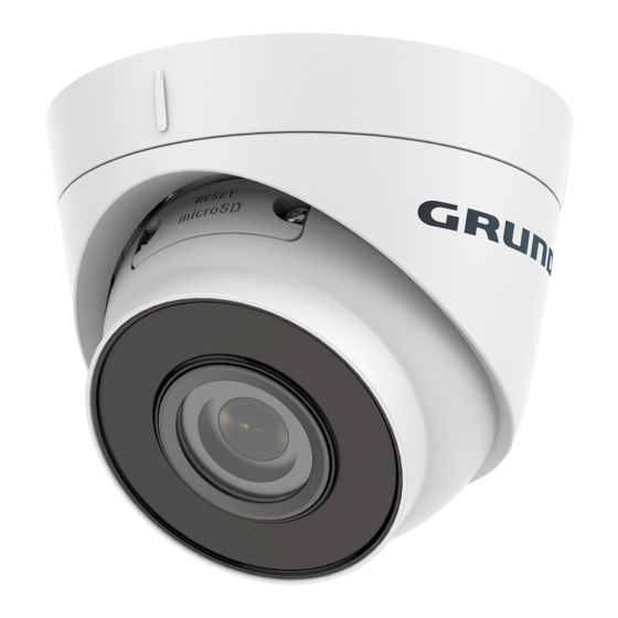
1 Appearance Description 1.1 Overview The overview of the network turret camera is shown below. Figure 1-1 Overview Turret Camera Table 1-1 Description of Turret Camera Description Enclosure Camera Body Mounting Base Power Cord Network Cable... -
Page 10: Installation
2 Installation 2.1 Memory Card Installation Note: Only the model GD-CI-AC5617E supports SD-card option. Steps: 1. Rotate the camera to expose the memory card slot. 2. Loosen the screws to remove the memory card slot cover. Remove cover 3. Insert the memory card. 4. -
Page 11: Ceiling Mounting
Ceiling Mounting Before you start: Both wall mounting and ceiling mounting are suitable for the turret camera. Ceiling mounting will be taken as an example in this section. And you can take steps of ceiling mounting as a reference for wall mounting. - Page 12 Disassemble the camera. 1). Rotate the camera to align the notch to one of the marks. 2). Insert a coin or another similar tool to the notch. 3). Press down the coin or another similar tool to pry the mounting base so as to separate the mounting base from the camera.
- Page 13 Figure 2-4 Fix the mounting base 5. Route the cables through the cable hole or the side opening. 6. Install the camera body back to the mounting base. Figure 2-5 Install the camera body 7. Connect the power cord and network cable. 8.
-
Page 14: Mounting With Junction Box
Figure 2-6 Adjust surveillance angle 1) Hold the camera body and rotate the enclosure to adjust the pan angle [0° to 360°]. 2) Move the camera body up and down to adjust the tilt angle [0° to 75°]. 3) Rotate the camera body to adjust the rotation angle [0° to 360°]. - Page 15 1. Paste the drill template (supplied) to the desired mounting position on the wall. 2. Drill the screw holes and the cable hole in the wall according to the drill template. Screw Hole Cable Hole Figure 2-7 Drill Template 3. Take apart the junction box, and fix the camera's mounting base with three MP4 screws on the junction box's cover.
- Page 16 Secure the Junction Box's Body on the Ceiling/Wall 5. Combine the junction box's cover with its body with supplied screws. 6. Repeat steps 5 to 8 of 2.2 Ceiling Mounting to complete the installation.
-
Page 17: Wall Mounting
2.4 Wall Mounting Note: You need to purchase a wall mounting bracket separately. Steps: 1. Drill four screw holes in the wall according to the holes of the bracket. 2. Install the bracket to the wall by aligning the four screw holes of the bracket with expansion screws on the wall. -
Page 18: Waterproof Measures
Figure 2-11 Install the Mounting Base on the Wall Mounting Bracket 5. Repeat steps 5 to 8 of 2.2 Ceiling Mounting to complete the installation. Waterproof Measures If the camera is installed outdoor, you should use the waterproof accessory or tapes to waterproof the cables. Otherwise, the cables might get wet or a short circuit occurs. -
Page 19: Install Network Cable Waterproof Jacket
2.5.1 Install Network Cable Waterproof Jacket ⑥ ② ④ ⑤ ③ ① Align ⑥ ① ④ ③ Figure 2-12 Install Waterproof Jacket Steps: 1. Feed the network cable through ① and ③ in order. 2. Fix ② on the network cable between ① and ③. 3. - Page 20 Figure 2-13 Waterproof Cables...
-
Page 21: Setting The Ip-Camera Over The Lan
3 Setting the IP-Camera over the LAN Note: You shall acknowledge that the use of the product with Internet access might be under network security risks. For avoidance of any network attacks and information leakage, please strengthen your own protection. If the product does not work properly, contact your dealer or the nearest service center for help. -
Page 22: Activating The Camera
Activation via Web Browser and Activation via Grundig IP-Finder Tool are supported. We will take activation via Grundig IP-Finder Tool and Activation via Web Browser as examples to introduce the camera activation. -
Page 23: Activation Via Grundig Ip-Finder Tool
Click OK to save the password and enter the live view interface. Activation via Grundig IP-Finder Tool The Grundig IP-Finder Tool is used for detecting the online device and activating the camera. Get the Grundig IP-Finder Tool from the supplied disk or the official... - Page 24 User manual for other two activation methods. Steps: 1. Run the Grundig IP-Finder Tool to search the online devices. 2. Check the device status from the device list and select the inactive device.
-
Page 25: Modifying The Ip Address
To view and configure the camera via LAN (Local Area Network), you need to connect the network camera in the same subnet with your Use the Grundig IP-Finder Tool to search and change the IP address of the device. We take modifying the IP Address via Grundig IP-Finder as an example to introduce the IP address modification. - Page 26 Figure 3-5 Modify the IP Address 4. Input the admin password and click Modify to activate your IP address modification. The batch IP address modification is supported by the Grundig IP- Finder. Please refer to the User Manual of Grundig IP-Finder for details.
-
Page 27: Accessing Via Web Browser
4 Accessing via Web Browser System Requirement: Operating System: Microsoft Windows XP SP1 and above version CPU: 2.0 GHz or higher RAM: 1G or higher Display: 1024×768 resolution or higher Web Browser: Internet Explorer 8.0 and above version, Apple Safari 5.0.2 and above version, Mozilla Firefox 5.0 and above version and Google Chrome 18 and above version Steps:... - Page 28 4. Click Login. Figure 4-1 Login Interface 5. Install the plug-in before viewing the live video and managing the camera. Please follow the installation prompts to install the plug- Note: You may have to close the web browser to finish the installation of the plug-in.
-
Page 29: Initializing The Memory Card
4.1 Initializing the Memory Card Note: Only the GD-CI-AC5617E supports SD-card. Steps: Check the memory card status by tapping on the Storage Status in the Device Settings interface. If the memory card status displays as Uninitialized, tap to initialize it. The status will then change to Normal. You can then start recording any event triggered video in the camera such as motion detection.
Need help?
Do you have a question about the GD-CI-AC2616E and is the answer not in the manual?
Questions and answers