Table of Contents
Advertisement
Quick Links
Advertisement
Table of Contents

Subscribe to Our Youtube Channel
Related Manuals for Grundig GD-CI-BC2626T


Summary of Contents for Grundig GD-CI-BC2626T
- Page 1 Quick Start Guide GD-CI-BC2626T GD-CI-BC4627T GD-CI-BC4637T grundig-security.com...
- Page 2 Use of this document and the subsequent results shall be entirely on the user’s own responsibility. Abetechs GmbH (Grundig Security) reserves the right to change the contents of this document without prior notice. Design and specifications are subject to change without prior notice.
- Page 3 OPEN SOURCE SOFTWARE LICENSE INFORMATION The software components provided with Grundig products may contain copyrighted software that is licensed under various open source software licenses. For detailed information about the...
- Page 4 The appearance of the products, functions and firmware or software upgrade may differ from this manual. GRUNDIG reserves the right to perform needed changes without prior notice. Safety Instructions Make sure that you only use the power adapter that is specified in the specifications sheet of the product.
- Page 5 Improper use or replacement of the battery may result in the hazard of explosion. Do not use any accessories that are not recommended by GRUNDIG. Do not modify the product in any way. If the product starts to smell or smoke comes out of the device, immediately stop using the product and disconnect it from the power supply to prevent fire or electric shocks.
- Page 6 Installation Instructions It is necessary to fix the device firmly if the product is installed on a wall or ceiling. Do not install the product on surfaces or in places that are vibrating. Do not install the product near radiation sources. Do not install the product near heat sources, like radiators or other equipment that produces some heat.
- Page 7 Special Installation Instructions for IP Cameras Make sure that the latest firmware is installed on the IP Device. You may get the latest firmware from www.grundig-security.com website or from techsupport@grundig-security.com.
-
Page 8: Table Of Contents
Table of Contents 1 Appearance Description ..............8 1.1 Camera ................8 2 Installation ..................10 2.1 Memory Card Installation ..........10 2.2 Camera Mounting ............12 2.2.1 Direct Mounting ............13 2.2.2 Mounting with a Junction Box ......... 15 2.3 Zoom and Focus Adjustment ......... -
Page 9: Appearance Description
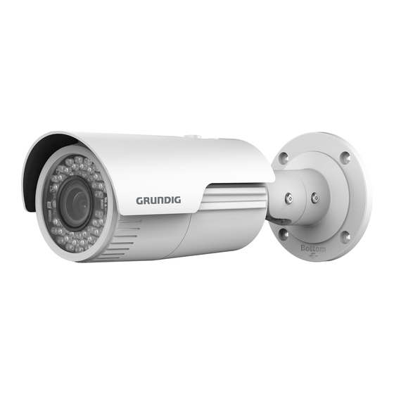
1 Appearance Description 1.1 Camera The overview of the camera is shown below. Overview of Camera Description Description Sun Shield Front Cover IR LED... - Page 10 Description Lens Zoom and Focus Lever Memory Card Slot Reset Button Camera Body Bracket Video Cable Network Cable Power Cord Note: Press RESET about 10s when the camera is powering on or rebooting to restore the default settings, including the user name, password, IP address, port No., etc.
-
Page 11: Installation
2 Installation 2.1 Memory Card Installation This series of cameras support memory card installation. Steps: 1. Rotate the lock screw counterclockwise to loosen it. Lock Screw Loosen the Lock Screw 2. Remove the sun shield. - Page 12 Figure 2-2 Remove the Sun Shield 3. Remove the front cover by rotating it counterclockwise. 4. Insert the memory card into the memory card slot. Figure 2-3 Insert the Memory Card...
-
Page 13: Camera Mounting
5. Rotate the front cover clockwise back to the camera and install the sun shield back. 6. Tighten the lock screw clockwise to tighten the sun shield. Rotating Label Tighten the Front Cover Note: For water-proof performance, align the rotating label on the front cover with that on the camera when you rotate the front cover clockwise. -
Page 14: Direct Mounting
2.2.1 Direct Mounting Steps: 1. Attach the drill template (supplied) to the wall or the ceiling where the camera is to be mounted. 2. Drill screw holes in the wall or ceiling according to the hole 1 on the drill template. Ceiling Mounting 1:Screw Hole for 2:Screw Hole for... - Page 15 Drill Template Drill Template Secure the Camera 6. Adjust the view angle. 3-axis (pan/tilt/rotation) adjusting allows adjustment for optimum camera rotation and placement. Follow the steps below to adjust the view angle. Pan Adjustment Steps: Loosen the lock screw 1. Adjust the panning position of the camera.
-
Page 16: Mounting With A Junction Box
Rotation Adjustment Steps: Loosen the lock screw 3. Rotate the rotation position to adjust the azimuth angle of the image. The adjusting range is from 0° to 360°. Tighten the lock screw 3. Panning 0° to 360° Rotation Lock Screw 1 Lock Screw 2 0°... - Page 17 Figure 2-8 Mounting with a Junction Box Steps: 1. Attach the drill template (supplied) to the wall where the camera is to be mounted and drill holes in the wall according to hole 2 on the drill template. See Figure 2.5. 2.
-
Page 18: Zoom And Focus Adjustment
7. Route the cables of the camera. Connect the cables and power on the camera to see if you can get an image on your monitoring screen. Note: If you can’t get the image, check the power and network connection before performing the next step. 8. - Page 19 5. Loosen the focus lever and move the lever between F (Far) and N (Near) to obtain the optimum focus. 6. Tighten the focus lever. 7. Install the sun shield and the front cover back to the camera. Zoom/Focus Lever Zoom and Focus Adjustment For cameras which are equipped with a motor-driven lens you can adjust the zoom and focus level on PTZ control panel by visiting the...
-
Page 20: Installation Of Network Cable Water-Proof Jacket (Optional)
2.4 Installation of Network Cable Water-proof Jacket (Optional) Purpose: If the camera is installed outdoor, you can adopt the water-proof accessory for the network cable after the camera is secured on the installation surface. Figure 2-11 Water-proof Accessory Components Table 2-1 Components Components Network Interface Socket O-Type Gasket... - Page 21 Steps: Feed the plugless network cable ⑦ through the lock nut ⑥, waterproof rubber gasket ⑤ (the rubber gasket inset ridge must face the waterproof endcap), and the waterproof endcap ④ in order. Crimp an RJ-45 network plug ③onto the end of the cable, taking care to insert the twisted pairs of wires in correct order.
- Page 22 Figure 2-12 Water-proof Accessory Installation...
-
Page 23: Setting The Network Camera Over The Lan
3 Setting the Network Camera over the Note: You shall acknowledge that the use of the product with Internet access might be under network security risks. For avoidance of any network attacks and information leakage, please strengthen your own protection. If the product does not work properly, contact your dealer or the nearest service center for help. -
Page 24: Activating The Camera
You are required to activate the camera first by setting a strong password for it before you can use the camera. Activation via Web Browser, Activation via Grundig IP-Finder, and Activation via Client Software are all supported. We will take activation via Grundig IP-Finder software and Activation via Web Browser as examples to introduce the camera activation. -
Page 25: Activation Via Ip-Finder Software
4. Confirm the password. 5. Click OK to save the password and enter the live view interface. 3.2.2 Activation via IP-Finder Software Grundig Finder software is used for detecting the online device and activating the camera. - Page 26 Get the Grundig Finder software from the supplied disk or the official website and install the software according to the prompts. Follow the steps to activate the camera, please refer to the User manual for other two activation methods. Steps: 1.
-
Page 27: Modifying The Ip Address
To view and configure the camera via LAN (Local Area Network), you need to connect the network camera in the same subnet with your Use the Grundig IP-Finder software or client software to search and change the IP address of the device. We take modifying the IP Address via Grundig IP-Finder software as an example to introduce the IP address modification. - Page 28 Modify the IP Address 4. Input the admin password and click Update to activate your IP address modification. The batch IP address modification is supported by the Grundig IP- Finder. Please refer to the User Manual of Grundig IP-Finder for details.
-
Page 29: Accessing Via Web Browser
4 Accessing via Web Browser System Requirement: Operating System: Microsoft Windows XP SP1 and above version CPU: 2.0 GHz or higher RAM: 1G or higher Display: 1024×768 resolution or higher Web Browser: Internet Explorer 8.0 and above version, Apple Safari 5.0.2 and above version, Mozilla Firefox 5.0 and above version and Google Chrome 18 and above version Steps:... - Page 30 4. Click Login. Login Interface 5. Install the plug-in before viewing the live video and managing the camera. Please follow the installation prompts to install the plug- Note: You may have to close the web browser to finish the installation of the plug-in.
-
Page 31: Initializing The Memory Card
4.1 Initializing the Memory Card Steps: Check the memory card status by tapping on the Storage Status in the Device Settings interface. If the memory card status displays as uninitialized, tap to initialize it. The status will then change to Normal. You can then start recording any event triggered video in the camera such as motion detection. - Page 32 QG-GD-CI-BC2626T-2019-09-18-V4-EN ©ABETECHS GMBH, DÜSSELDORF, GERMANY grundig-security.com...
Need help?
Do you have a question about the GD-CI-BC2626T and is the answer not in the manual?
Questions and answers