Table of Contents
Advertisement
Advertisement
Table of Contents

Related Manuals for Grundig GD-CI-AC1616V


Summary of Contents for Grundig GD-CI-AC1616V
- Page 2 Please find the latest version at WWW.GRUNDIG-SECURITY.COM Limitation of Liability / Legal Disclaimer Abetechs GmbH (Grundig Security) undertakes all reasonable efforts to verify the integrity and correctness of the contents in this document, but no formal guarantee shall be provided. Use of this document and the subsequent results shall be entirely on the user’s...
- Page 3 OPEN SOURCE SOFTWARE LICENSE INFORMATION The software components provided with Grundig products may contain copyrighted software that is licensed under various open source software licenses. For detailed information about the...
- Page 4 You may obtain the complete corresponding open source part of a specific product from us for a period of three years after our last shipment of this product by sending an email to: info@grundig- security.com Safety Instruction Make sure that you only use the power adapter that is specified in the specifications sheet of the product.
- Page 5 Improper use or replacement of the battery may result in the hazard of explosion. Do not use any accessories that are not recommended by GRUNDIG. Do not modify the product in any way. If the product starts to smell or smoke comes out of the device, immediately stop using the product and disconnect it from the power supply to prevent fire or electric shocks.
- Page 6 If the product supports IR, you need to take some precautions to prevent IR reflection. Do not install the product close to reflective surfaces of objects as this may cause reflection. If the product has a dome cover, please remove the protection film only after installation to prevent dust or grease on the camera which can cause reflection.
-
Page 7: Table Of Contents
Table of Contents 1 Appearance Description ............... 7 2 Installation ................... 9 3 Setting the Network Camera over the LAN ......... 13 3.1 Wiring ................13 3.2 Activating the Camera ........... 14 Activation via Web Browser ........ 14 Activation via IP-Finder Software ......15 3.3 Modifying the IP Address .......... -
Page 8: Appearance Description
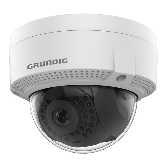
1 Appearance Description This series of cameras has two types, and shares the same appearance, shown as the figure 1-1. Camera Overview... - Page 9 Description of Type I/II Camera Description Mounting Base Tilt Adjusting Screw Bubble Network Interface Power Interface IR LED Lens Black Liner Safety Rope Note: Power on the camera when pressing the RESET button, and press button for another 10 seconds to restore the default settings, including the user name, password, IP address, port No., etc.
-
Page 10: Installation
2 Installation Steps: 1. Attach the dill template to the ceiling. 2. Drill the screw holes and cable hole (optional) in the ceiling according to the drill template. Note: Cable hole is required when you adopt ceiling outlet to route the cables. - Page 11 Remove the Bubble 4. Fix the mounting base on the ceiling with supplied screws. Fix the Mounting Base 5. Route the cables through the cable hole. Note: If required, you can route cables through the side opening on the side of the mounting base. Side Opening...
- Page 12 Side Opening 6. Connect the corresponding cables, such as power cable and network cable. 7. Power on the camera to check whether the image on the monitor is gotten from the optimum angle. If not, adjust the camera to get an optimum angle.
- Page 13 ● Type II camera supports 3-axis adjustment. Loosen the tilt adjusting screw to adjust the tilt angle [0° to 75°], hold the black liner to adjust the pan angle [0° to 355°], and hold the lens to rotate the camera [0° to 355°]. See the figure below. 0°...
-
Page 14: Setting The Network Camera Over The Lan
3 Setting the Network Camera over the Note: You shall acknowledge that the use of the product with Internet access might be under network security risks. For avoidance of any network attacks and information leakage, please strengthen your own protection. If the product does not work properly, contact your dealer or the nearest service center for help. -
Page 15: Activating The Camera
You are required to activate the camera first by setting a strong password for it before you can use the camera. Activation via Web Browser, Activation via Grundig IP-Finder, and Activation via Client Software are all supported. We will take activation via Grundig IP-Finder software and Activation via Web Browser as examples to introduce the camera activation. -
Page 16: Activation Via Ip-Finder Software
Activation via IP-Finder Software Grundig Finder software is used for detecting the online device and activating the camera. Get the Grundig Finder software from the supplied disk or the official website and install the software according to the prompts. Follow the... - Page 17 2. Check the device status from the device list and select the inactive device. Grundig IP-Finder Interface Note: The software supports activating the camera in batch. Refer to the user manual of Grundig Finder software for details. 3. Create and input the new password in the password field, and confirm the password.
-
Page 18: Modifying The Ip Address
To view and configure the camera via LAN (Local Area Network), you need to connect the network camera in the same subnet with your Use the Grundig IP-Finder software or client software to search and change the IP address of the device. We take modifying the IP Address via Grundig IP-Finder software as an example to introduce the IP address modification. - Page 19 Modify the IP Address 4. Input the admin password and click Modify to activate your IP address modification. The batch IP address modification is supported by the Grundig IP- Finder. Please refer to the User Manual of Grundig IP-Finder for details.
-
Page 20: Accessing Via Web Browser
4 Accessing via Web Browser System Requirement: Operating System: Microsoft Windows XP SP1 and above version CPU: 2.0 GHz or higher RAM: 1G or higher Display: 1024×768 resolution or higher Web Browser: Internet Explorer 8.0 and above version, Apple Safari 5.0.2 and above version, Mozilla Firefox 5.0 and above version and Google Chrome 18 and above version Steps:... - Page 21 Download Plug-in 6. Reopen the web browser after the installation of the plug-in and repeat steps 2 to 4 to login. Note: For detailed instructions of further configuration, please refer to the user manual. WWW.GRUNDIG-SECURITY.COM QG-GD-CI-AC1616V-2018-10-08-V3-EN ©ABETECHS GMBH, DÜSSELDORF, GERMANY...
Need help?
Do you have a question about the GD-CI-AC1616V and is the answer not in the manual?
Questions and answers