Table of Contents
Advertisement
Quick Links
Advertisement
Table of Contents

Related Manuals for Grundig GD-TI-AT30105K


Summary of Contents for Grundig GD-TI-AT30105K
- Page 2 WWW.GRUNDIG-SECURITY.COM Limitation of Liability / Legal Disclaimer Abetechs GmbH (Grundig Security) undertakes all reasonable efforts to verify the integrity and correctness of the contents in this document, but no formal guarantee shall be provided. Use of this document and the subsequent results shall be entirely on the user’s own responsibility.
- Page 3 OPEN SOURCE SOFTWARE LICENSE INFORMATION The software components provided with Grundig products may contain copyrighted software that is licensed under various open source software licenses. For detailed information about the contained open source software packages, the used package versions, license information and complete license terms, please refer to the product detail pages on our website.
- Page 4 Improper use or replacement of the battery may result in the hazard of explosion. Do not use any accessories that are not recommended by GRUNDIG. Do not modify the product in any way. If the product starts to smell or smoke comes out of the device, immediately stop using the product and disconnect it from the power supply to prevent fire or electric shocks.
- Page 5 liability or responsibility for problems caused by attempted and unauthorized repair and maintenance. Installation Instructions It is necessary to fix the device firmly if the product is installed on a wall or ceiling. Do not install the product on surfaces or in places that are vibrating. Do not install the product near radiation sources.
- Page 6 Special Installation Instructions for IP Cameras Make sure that the latest firmware is installed on the IP Device. You may get the latest firmware from www.grundig-security.com website from techsupport@grundig-security.com.
-
Page 7: Table Of Contents
Table of Contents 1 Camera Introduction ................... 8 1.1 Overview ....................8 1.2 Appearance ..................... 8 1.3 Dimensions (mm) ..................9 1.4 Connect ....................11 2 Operation ....................12 2.1 Installation and cable connection ............12 3. Common Faults ..................15 4 Network Set and Access ................ -
Page 8: Camera Introduction
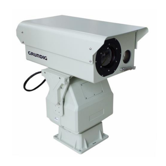
1 Camera Introduction 1.1 Overview The GD-TI-AT30105K Thermal Positioning System Camera is a series of camera specially designed for long range day and night surveillance. In the daytime, it uses a telephoto lens and high-definition camera imaging, which can take into account both short-range and large-range search and long-distance feature image collection;... -
Page 9: Dimensions (Mm)
Camera and PT cable interface Outgoing line interface Figure 1-2 Back Lateral View 1.3 Dimensions (mm) Figure 1-3 Front View... - Page 10 Figure 1-4 Lateral View Figure 1-5 Front and side view of PTZ...
-
Page 11: Connect
Figure 1-6 Mounting Hole at the base of PT 1.4 Connect The interface between the host and PTZ uses a 26-core waterproof aviation connector. For details, please refer to the following: Pin No. Red RS485A Black White TX+ Purple TX- definition RS485B (machine) -
Page 12: Operation
2 Operation 2.1 Installation and cable connection 2.1.1 Installation Mount the pinboard on the camera with M6 × 12 hexagonal screw (already done). Then mount the camera on PTZ with M6 × 20 hexagonal screw. Do not use screws too long in case of damaging the base plate of the camera; Do not use screws too short in case of unsecure installation. - Page 13 Make a support according to the chart shown above. Then use suitable bolts and nuts to secure the camera on the support. The support should be able to bear more than 100kg. 2.1.2 Aviation Plug Installation Figure 2-3 Aviation Plug Hole Figure 2-4 Aviation plug Pin When installing, please insert the head hole into the socket, make sure that the pin is inserted into the socket, then twist the upper fixed ring upward and to the right, and...
- Page 14 2.1.3 Cable Connection Power supply Outgoing RS485 reserved Cable Network cable Computer Thermal Positioning System Figure 2-6 Connection Diagram...
-
Page 15: Common Faults
3. Common Faults The table below includes the common faults during operation. Whenever these problems occur, you may refer to this table or contact us directly for proper solution. Fault Possible Cause Solution Power damage or under Replace the original power. power No movement and video after... - Page 16 Select auto correction or restore Auto correction is not ON. default. Super high or low Inappropriate brightness Adjust brightness, contrast to brightness and contrast parameters adapt to corresponding setting environment or restore default.
-
Page 17: Network Set And Access
4 Network Set and Access A number of parameters necessitates configuration before using. Parameters need to configured include: IP address, subnet mask and port number. Default IP address for camera: 192.168.1.64 User: admin Password: Abc.12345 Note: The specific login interface is subject to the actual login. 4.1 Accessing by Web Browsers 4.1.1 Product Overview Network thermal imaging is mainly connected with PC through a switch or router. - Page 18 Figure 4-1 Login Step 2, Enter the password of the admin user. The initial password is Abc.12345. Step 3, Click Login. After the login is successful, the Preview screen is displayed, as shown in Figure 4-2. Figure 4-2 Preview (2) Logout Click "Logout"...
- Page 19 pan-tilt function option bar. After logging in to the web page, click the Preview tab. The system displays the Preview interface, as shown in Figure 4-3. Figure 4-3 Preview interface The preview interface of the WEB client contains four function bars: (1) System menu bar, click the tab on the system menu bar to enter the corresponding function interface.
- Page 20 Main code Play the main code stream with high definition stream Secondary Play the secondary code stream with low resolution code stream Full screen Display video screen in full screen Capture Click this icon to grab a current video screen and save it in the set storage path.
- Page 21 The focus speed is mainly used for the lens focus control speed, and the larger the value. Figure 4-5 PTZ control 4.1.3.4 PTZ function option bar Introduce PTZ functions, including cruise, preset points, horizontal scan, and more. Figure 4-6 PTZ function Preset Position After the preset position is set, the device can be quickly positioned to the corresponding position by viewing the preset position.
- Page 22 Step 2, Select the preset number and enter the name; Step 3, Control the lens and the PTZ to the specified position; Step 4, Click the “Settings” to complete the configuration. Click the “Call” icon to turn the camera to the position corresponding to the preset position, and click the “Delete”...
- Page 23 Step 4, Click the Start button and the device starts a horizontal scan. Click the Stop button or control the direction to stop the horizontal scan. Figure 4-8 Horizontal scan Auxiliary Function Figure 4-9 Auxiliary Function The auxiliary function can be turned on through the auxiliary switch, the specific function description is as follows: Auxiliary Function Description...
- Page 24 4.1.4.1 Image Parameter Switch to Setting-Channels Settings-Image settings-Image parameter. In channel 1, the visible light image parameter settings include Basic parameter, Exposure, Focus Parameter, Day Night, Backlight, WB, Enhance, Video Adjust, Other, Dual Video, ROI Zoom. Adjust the image parameters according to the actual environment.
- Page 25 Figure 4-11 Defog In channel 2, the thermal imaging image parameter settings include Basic parameter, Digital zoom, 3D noise reduction, Dual Video, ROI Zoom and the image parameters can be adjusted according to the actual environment. Figure 4-12 Image parameter setting (channel 2) 4.1.4.2 Thermal Parameter Switch to Setting-Channels Settings-Image settings-Thermal parameter.
- Page 26 Figure 4-13 Thermal parameters Graphic adjustment Adjust the image according to the actual environment. As shown in Figure 3-14. Figure 4-14 Graphic adjustment...
- Page 27 Detailed function descriptions: Function Description Brightness Linearly adjusts the overall brightness of the image. The larger the value, the brighter the image, and vice versa. Contrast Adjust the contrast of the image. The larger the value, the larger the contrast of the image, and the smaller the contrast.
- Page 28 Before using this function, you must aim the camera at the scene with a single background. For example, it can be aimed at a cloudless sky, or it can be corrected after being covered by a lens cover. Whether to turn on After it is turned on, it will automatically calibrate automatic time calibration according to the set time interval.
- Page 29 Detailed function descriptions: Function Description Whether to enable After ticking, enable and enable the function Image pixel threshold The smaller the value, the more sensitive. Baffle block time The retention time after the block film is blocked. After this time has elapsed, the baffle is removed. ...
- Page 30 4.1.5 Intelligent analysis 4.1.5.1 Intrusion detection settings The area intrusion detection function can detect whether there is an object in the video entering the set area, and link the alarm according to the judgment result. Figure 4-19 Intrusion detection settings Switch to Setting-Alarm Settings-Intelligent Analysis-Intrusion detection settings.
- Page 31 Please refer to the following table for detailed function description Function Description Channel Channel 1 sets visible light intelligent analysis rules; Channel 2 sets thermal imaging intelligent analysis rules Intrusion detection enable After opening, after the target enters the area, an alarm will be triggered Object marking After opening, the detected target will be marked...
- Page 32 Other intelligent analysis functions can be selected and set according to their own needs under the "Settings-Alarm Settings-Intelligent analysis" interface. Note: Some functions require equipment support, please refer to the actual product. 4.1.6 Hot alarm When the thermal camera detects the hot target, it will make an alarm identification and frame the alarm target.
- Page 33 Figure 4-22 Hot Alarm-Linkage method Please refer to the table below for some detailed function descriptions. Function Description Hot Alarm Enable After it is turned on, it will alarm when a hot target is detected Maximum Size Maximum size of detected target Minimum Size Minimum size of detected target Maximum Targets Number...
Need help?
Do you have a question about the GD-TI-AT30105K and is the answer not in the manual?
Questions and answers