Table of Contents
Advertisement
Quick Links
Advertisement
Table of Contents

Related Manuals for Arcteq AQ-V211


Summary of Contents for Arcteq AQ-V211
- Page 1 AQ-V211 Voltage protection device Instruction manual...
-
Page 2: Table Of Contents
3.10 Configuring user levels and their passwords............... 52 4 Functions unctions ...................................................... 55 4.1 Functions included in AQ-V211.................... 55 4.2 Measurements........................56 4.2.1 Voltage measurement and scaling ................56 4.2.2 Voltage memory ......................69 4.2.3 Frequency tracking and scaling ................. 72 4.3 General menu........................ - Page 3 6 Connections and applic 6 Connections and applica a tion examples tion examples..................................264 6.1 Connections of AQ-V211....................264 6.2 Application example and its connections................266 6.3 Trip circuit supervision (95) ....................267 7 Construction and installa 7 Construction and installation tion ....................
- Page 4 8.3 Tests and environmental ....................313 9 Or 9 Ordering inf dering informa ormation tion ..............................................316 10 Contact and r 10 Contact and re e f f er erence inf ence informa ormation tion....................................318 © Arcteq Relays Ltd IM00030...
- Page 5 Nothing contained in this document shall increase the liability or extend the warranty obligations of the manufacturer Arcteq Relays Ltd. The manufacturer expressly disclaims any and all liability for any damages and/or losses caused due to a failure to comply with the instructions contained herein or caused by persons who do not fulfil the aforementioned requirements.
-
Page 6: Document Inf
- Order codes revised. - Added double ST 100 Mbps Ethernet communication module and Double RJ45 10/100 Mbps Ethernet communication module descriptions Revision 2.02 Date 7.7.2020 Changes - A number of image descriptions improved. Revision 2.03 Date 27.8.2020 © Arcteq Relays Ltd IM00030... - Page 7 - Improvements to many drawings and formula images. - Improved and updated device user interface display images. - AQ-V211 Functions included list Added: Voltage memory, indicator objects, switch-on-to- fault, vector jump protection, programmable control switch, mA output control and measurement recorder.
-
Page 8: Version 1 Revision Notes
Revision 2.09 Date 14.3.2023 - Updated the Arcteq logo on the cover page and refined the manual's visual look. - Added the "Safety information" chapter and changed the notes throughout the document accordingly. - Changed the "IED user interface" chapter's title to "Device user interface" and replaced all 'IED' terms with 'device' or 'unit'. -
Page 9: Safety Information
A A Q Q -V211 -V211 1 Document information Instruction manual Version: 2.10 Changes • The first revision for AQ-V211. Revision 1.01 Date 22.11.2013 Changes • Application example for the trip circuit supervision added. Revision 1.02 Date 30.1.2014 Changes • Added the df/dt and the synchrocheck functions. -
Page 10: Abbreviations
CBFP – Circuit breaker failure protection CLPU – Cold load pick-up CPU – Central processing unit CT – Current transformer CTM – Current transformer module CTS – Current transformer supervision DG – Distributed generation DHCP – Dynamic Host Configuration Protocol © Arcteq Relays Ltd IM00030... - Page 11 RMS – Root mean square RSTP – Rapid Spanning Tree Protocol RTD – Resistance temperature detector RTU – Remote terminal unit SCADA – Supervisory control and data acquisition SG – Setting group SOTF – Switch-on-to-fault SW – Software © Arcteq Relays Ltd IM00030...
- Page 12 A A Q Q -V211 -V211 1 Document information Instruction manual Version: 2.10 THD – Total harmonic distortion TRMS – True root mean square VT – Voltage transformer VTM – Voltage transformer module VTS – Voltage transformer supervision © Arcteq Relays Ltd IM00030...
-
Page 13: General
Version: 2.10 2 General The AQ-V211 voltage protection device is a member of the AQ 200 product line. The hardware and software are modular: the hardware modules are assembled and configured according to the application's I/O requirements and the software determines the available functions. This manual describes the specific application of the AQ-V211 voltage protection device. -
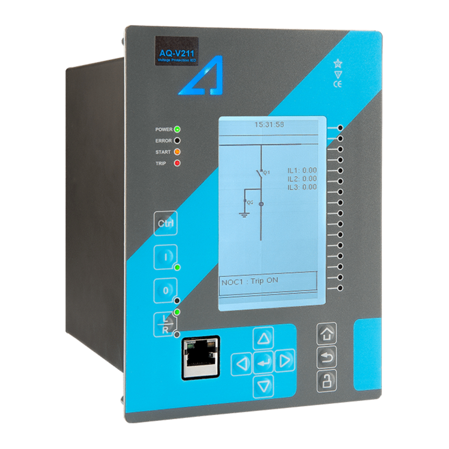
Page 14: Device User Int Vice User Interface Erface
5. Eight (8) buttons for device local programming: the four navigation arrows and the E E nt nter er button in the middle, as well as the Home Home, the Back Back and the password activation buttons. 6. One (1) RJ-45 Ethernet port for device configuration. © Arcteq Relays Ltd IM00030... -
Page 15: Mimic And Main Menu
LEDs you have set. The password activation button (with the padlock icon ) takes you to the password menu where you can enter the passwords for the various user levels (User, Operator, Configurator, and Super-user). © Arcteq Relays Ltd IM00030... -
Page 16: Navigation In The Main Configuration Menus
The General main menu is divided into two submenus: the Device info tab presents the information of the device, while the Function comments tab allows you to view all comments you have added to the functions. © Arcteq Relays Ltd IM00030... - Page 17 A A Q Q -V211 -V211 3 Device user interface Instruction manual Version: 2.10 Figure. 3.3 - 4. General menu structure. Device info Figure. 3.3 - 5. Device info. © Arcteq Relays Ltd IM00030...
- Page 18 If set to 0 s, this feature is not in use. 0: - When activated, all LEDs are lit up. LEDs with LED test 0: - 1: Activated multiple possible colors blink each color. © Arcteq Relays Ltd IM00030...
- Page 19 Monitor profile Function comments Function comments displays notes of each function that has been activated in the Protection, Control and Monitoring menu. Function notes can be edited by the user. Figure. 3.3 - 6. Function comments. © Arcteq Relays Ltd IM00030...
-
Page 20: Protection Menu
The Protection main menu includes the Stage activation submenu as well as the submenus for all the various protection functions, categorized under the following modules: "Arc protection", "Current", "Voltage", "Frequency", "Sequence" and "Supporting" (see the image below). The available functions depend on the device type in use. © Arcteq Relays Ltd IM00030... - Page 21 For example, the I> (overcurrent) protection stage can be found in the "Current" module, whereas the U< (undervoltage) protection stage can be found in the "Voltage" module. Figure. 3.4 - 9. Submenus for Stage activation. © Arcteq Relays Ltd IM00030...
- Page 22 Figure. 3.4 - 10. Accessing the submenu of an individual activated stage. Each protection stage and supporting function has five sections in their stage submenus: "Info", "Settings", " Registers", "I/O" and "Events". Figure. 3.4 - 11. Info. © Arcteq Relays Ltd IM00030...
- Page 23 Voltage and current transformers nominal values can be set at Measurement → Transformers . • Delay type and operating time delay settings are described in detail in General properties of a protection function chapter. © Arcteq Relays Ltd IM00030...
- Page 24 Data included in the register depend on the protection function. You can clear the the operation register by choosing "Clear registers" → "Clear". "General event register" stores the event generated by the stage. These general event registers cannot be cleared. © Arcteq Relays Ltd IM00030...
- Page 25 "Blocking input control" allows you to block stages. The blocking can be done by using any of the following: • digital inputs • logical inputs or outputs • the START, TRIP or BLOCKED information of another protection stage • object status information. © Arcteq Relays Ltd IM00030...
-
Page 26: Control Menu
, for configuring the objects ( Objects) , for setting the various control functions ( Control functions) , and for configuring the inputs and outputs ( Device I/O) . The available control functions depend on the model of the device in use. © Arcteq Relays Ltd IM00030... - Page 27 • F F or orce se ce set t ting gr ting group change oup change: this setting allows the activation of a setting group at will (please note that Force SG change enable must be "Enabled"). © Arcteq Relays Ltd IM00030...
- Page 28 Each activated object is visible in the Objects submenu. By default all objects are disabled unless specifically activated in the Controls → Controls enabled submenu. Each active object has four sections in their submenus: "Settings", "Application control" ("App contr"), "Registers" and "Events". These are described in further detail below. © Arcteq Relays Ltd IM00030...
- Page 29 A request is considered to have failed when the object does not change its status as a result of that request. • C C lear sta lear statistics tistics: statistics can be cleared by choosing "Clear statistics" and then "Clear". © Arcteq Relays Ltd IM00030...
- Page 30 By default, the access level is set to "Configurator". • You can use digital inputs to control the object locally or remotely. Remote controlling via the bus is configured on the protocol level. © Arcteq Relays Ltd IM00030...
- Page 31 Object blocking is done in the "Blocking input control" subsection. It can be done by any of the following: digital inputs, logical inputs or outputs, object status information as well as stage starts, trips or blocks. Figure. 3.5 - 23. Registers section. © Arcteq Relays Ltd IM00030...
- Page 32 In the image series below, the user has activated three control functions. The user accesses the list of activated control stages through the "Control functions" module, and selects the control function for further inspection. Figure. 3.5 - 25. Control functions submenu. © Arcteq Relays Ltd IM00030...
- Page 33 While the function is activated and disabled in the Control → Controls enabled submenu, you can disable the function through the "Info" section (the [function name] mode at the top of the section). Figure. 3.5 - 27. Settings section. © Arcteq Relays Ltd IM00030...
- Page 34 Data included in the register depend on the control function. You can clear the the operation register by choosing "Clear registers" → "Clear". "General event register" stores the event generated by the stage. These general event registers cannot be cleared. © Arcteq Relays Ltd IM00030...
- Page 35 "Blocking input control" allows you to block stages. The blocking can be done by using any of the following: • digital inputs. • logical inputs or outputs. • the START, TRIP or BLOCKED information of another protection stage. • object status information. © Arcteq Relays Ltd IM00030...
- Page 36 Mimic Indicator", "Logic signals" and "GOOSE matrix". Please note that digital inputs, logic outputs, protection stage status signals (START, TRIP, BLOCKED, etc.) as well as object status signals can be connected to an output relay or to LEDs in the "Device I/O matrix" section. © Arcteq Relays Ltd IM00030...
- Page 37 "Event masks" subsection you can determine which events are masked –and therefore recorded into the event history– and which are not. Figure. 3.5 - 33. Digital outputs section. All settings related to digital outputs can be found in the "Digital outputs" section. © Arcteq Relays Ltd IM00030...
- Page 38 LED quick displays and the matrices. You can also modify the color of the LED ("LED color settings") between green and yellow; by default all LEDs are green. © Arcteq Relays Ltd IM00030...
- Page 39 These signals can be used in a variety of situations, such as for controlling the logic program, for function blocking, etc. You can name each switch and set the access level to determine who can control the switch. © Arcteq Relays Ltd IM00030...
- Page 40 Logical output signals can be used as the end result of a logic that has been built in the AQtivate 200 setting tool. The end result can then be connected to a digital output or a LED in the matrix, block functions and much more. © Arcteq Relays Ltd IM00030...
-
Page 41: Communication Menu
Communication → Connections submenu. As a standard, the devices support the following communication protocols: • NTP • IEC 61850 • Modbus/TCP • Modbus/RTU • IEC-103 • IEC -101/104 • SPA • DNP3 • ModbusIO. © Arcteq Relays Ltd IM00030... - Page 42 When communicating with a device via the front Ethernet port connection, the IP address is always 192.168.66.9. SERIAL COM1 & COM2 SERIAL COM1 & COM2 SERIAL COM1 and SERIAL COM2 are reserved for serial communication option cards. They have the same settings as the RS-485 port. © Arcteq Relays Ltd IM00030...
- Page 43 • DNP3: supports both serial and Ethernet communication. • ModbusIO: used for connecting external devices like ADAM RTD measurement units. NOTICE! TICE! Please refer to the "Communication" chapter for a more detailed text on the various communication options. © Arcteq Relays Ltd IM00030...
-
Page 44: Measurement Menu
Transformers menu is used for setting up the measurement settings of available current transformer modules or voltage transformer modules. Some unit types have more than one CT or VT module. Some unit types like AQ-S214 do not have current or voltage transformers at all. © Arcteq Relays Ltd IM00030... - Page 45 These settings are then used for scaling the voltage channel input voltages to primary and per unit values as well as power and energy measurement values if current measurements are also available. Frequency Figure. 3.7 - 45. Frequency submenu. © Arcteq Relays Ltd IM00030...
- Page 46 • "Harmonics" displays harmonics up to the 31 harmonic for all four voltages (U1, U2, U3, U4); each component can be displayed as absolute or percentage values, and as primary or secondary voltages or in per-unit values. © Arcteq Relays Ltd IM00030...
-
Page 47: Measurement Menu
Transformers Figure. 3.8 - 48. Transformers submenu. The AQ-V211 device only has the one voltage transformer module, and its scaling settings can be accessed here. Sometimes a mistake in the wiring can cause the polarity to be changed; in such cases, you can invert the polarity of each phase current individually. - Page 48 When "Sampling mode" is set to "Tracking", the device uses the measured frequency value as the system nominal frequency. There are three reference measuring points; the order of the reference points can be changed. Voltage measurement Figure. 3.8 - 50. Voltage measurement submenu. © Arcteq Relays Ltd IM00030...
-
Page 49: Monitoring Menu
( Monitors enabled ), setting the various monitoring functions ( Monitor functions ), controlling the disturbance recorder ( Disturbance REC ) and accessing the device diagnostics ( Device diagnostics ). The available monitoring functions depend on the type of the device in use. © Arcteq Relays Ltd IM00030... - Page 50 You can activate the selected monitor functions in the Monitors enabled submenu. By default all the control functions are disabled. All activated functions can be viewed in the Monitor functions submenu (see the section "Monitor functions" below for more information). © Arcteq Relays Ltd IM00030...
- Page 51 The Disturbance recorder submenu has the following settings: • "Recorder enabled" enables or disables the recorder. • "Recorder status" indicates the status of the recorder. • "Clear record" records the chosen record in the memory. © Arcteq Relays Ltd IM00030...
- Page 52 • "Rec. digital channels" is a long list of the possible digital channels that can be recorded (including primary and secondary amplitudes and currents, calculated signals, TRMS values, sequence components, inputs and outputs, etc.). © Arcteq Relays Ltd IM00030...
-
Page 53: Configuring User Levels And Their Passwords
The different user levels and their star indicators are as follows (also, see the image below for the HMI view): • Super user (***) • Configurator (**) • Operator (*) • User ( - ) © Arcteq Relays Ltd IM00030... - Page 54 • Configurator: Can change most settings such as basic protection pick-up levels or time delays, breaker control functions, signal descriptions etc. and can operate breakers and other equipment. • Super user: Can change any setting and can operate breakers and other equipment. © Arcteq Relays Ltd IM00030...
- Page 55 A A Q Q -V211 -V211 3 Device user interface Instruction manual Version: 2.10 NOTICE! TICE! Any user level with a password automatically locks itself after half an hour (30 minutes) of inactivity. © Arcteq Relays Ltd IM00030...
-
Page 56: Functions Unctions
Instruction manual Version: 2.10 4 Functions 4.1 Functions included in AQ-V211 The AQ-V211 voltage protection relay includes the following functions as well as the number of stages in those functions. Table. 4.1 - 4. Protection fucntions of AQ-V211. Name ANSI Description U>... -
Page 57: Measurements
Milliampere output control ΔV/Δa/Δf Synchrocheck function Synchronizer GSYN ΔV/Δa/Δf (onl only y in Function package B!) Table. 4.1 - 6. Monitoring functions of AQ-V211. Name ANSI Description Voltage transformer supervision Disturbance recorder MREC Measurement recorder VREC Measurement value recorder 4.2 Measurements... - Page 58 VT ratings. In the figure below, three line-to-neutral voltages are connected along with the zero sequence voltage; therefore, the 3LN+U4 mode must be selected and the U4 channel must be set as U0. Other possible connections are presented later in this chapter. © Arcteq Relays Ltd IM00030...
- Page 59 ( Protection → Voltage → [protection stage menu] → INFO ; see the image below). The number of available protection functions depends on the device type. Figure. 4.2.1 - 59. Selecting the measured magnitude. © Arcteq Relays Ltd IM00030...
- Page 60 • 2LL+U3+U4 (two line-to-line voltages and the U3 and the U4 channels can be used for synchrochecking, zero sequence voltage, or for both) The 3LN+U0 is the most common voltage measurement mode. See below for example connections of voltage line-to-line measurement (3LL on the left, 2LL on the right). © Arcteq Relays Ltd IM00030...
- Page 61 In the image below is an example of 2LL+U0+SS, that is, two line-to-line measurements with the zero sequence voltage and voltage from side 2 for Synchrocheck. Since U0 is available, line-to-neutral voltages can be calculated. Figure. 4.2.1 - 62. 2LL+U0+SS settings and connections. © Arcteq Relays Ltd IM00030...
- Page 62 The measured voltage amplitude does not match one of the measured phases./ Check the wiring connections between the injection device or the VTs and the device. The calculated U0 is measured even though it should not. © Arcteq Relays Ltd IM00030...
- Page 63 "U4 mode U0 or SS" has been set to 2: Open the "U0" mode. delta Voltage 0: Disabled Activates the voltage memory. The "Voltage memory" memory 1: Activated Disabled chapter describes the function in more detail. © Arcteq Relays Ltd IM00030...
- Page 64 VT scaling A feedback value; the scaling factor for the primary factor p.u. Pri voltage's per-unit value. VT scaling A feedback value; the scaling factor for the factor p.u. Sec secondary voltage's per-unit value. © Arcteq Relays Ltd IM00030...
- Page 65 The secondary RMS voltage measurement from each of the voltage Ux 0.00…500.00 0.01 voltage channels. ("Ux Volt sec") Secondary voltage Ux 0.00…500.00 0.01 The secondary TRMS voltage (inc. harmonics up to 31 TRMS measurement from each of the voltage channels. ("UxVolt TRMS sec") © Arcteq Relays Ltd IM00030...
- Page 66 ("Pos.seq.Volt.sec") Secondary negative 0.00…4 The secondary measurement from the calculated sequence voltage 0.01 800.00 negative sequence voltage. ("Neg.seq.Volt.sec") Secondary zero sequence 0.00…4 The secondary measurement from the calculated zero voltage 0.01 800.00 sequence voltage. ("Zero.seq.Volt.sec") © Arcteq Relays Ltd IM00030...
- Page 67 UL1 mag") System voltage magnitude 0.00…1 The primary RMS line-to-neutral UL2 voltage (measured or calculated). You 0.01 can also select the row where the unit for this is kV. ("System 000.00 volt UL2 mag") © Arcteq Relays Ltd IM00030...
- Page 68 UL23 0.00…360.00 0.01 The primary line-to-line angle UL23 (measured or calculated). ("System volt UL23 ang") System voltage angle UL31 0.00…360.00 0.01 The primary line-to-line angle UL23 (measured or calculated). ("System volt UL31 ang") © Arcteq Relays Ltd IM00030...
- Page 69 Defines how the harmonics are displayed: in p.u. values, as 1: Primary V display primary voltage values, or as secondary voltage values. 2: Secondary V Maximum 0.00…100 Displays the maximum harmonics value of the selected harmonics value 0.01 000.00 voltage input Ux. ("UxMaxH") © Arcteq Relays Ltd IM00030...
-
Page 70: Voltage Memory
2. At least one phase current must be above the set value for the "Measured current condition 3I>" parameter. This setting limit is optional. Figure. 4.2.2 - 65. Distance protection characteristics and directional overcurrent. © Arcteq Relays Ltd IM00030... - Page 71 Table. 4.2.2 - 19. Measurement inputs of the voltage memory function. Signal Description Time base IL1RMS RMS measurement of phase L1 (A) current IL2RMS RMS measurement of phase L2 (B) current IL3RMS RMS measurement of phase L3 (C) current RMS measurement of voltage U © Arcteq Relays Ltd IM00030...
- Page 72 When the "Forced CT f tracking" parameter is activated and voltages are gone, the frequency from the selected current-based reference channel 3 (the current from IL3) is used for current sampling. This eliminates any possible measurement errors in the fixed frequency mode. Figure. 4.2.2 - 67. Frequency reference channels. © Arcteq Relays Ltd IM00030...
-
Page 73: Frequency Tracking And Scaling
The benefit of frequency tracking is that the measurements are within a pre-defined accuracy range even when the fundamental frequency of the power system changes. Frequency independent current and voltage measurement accuracy is achieved with algorithms specified in patent US 10,809,287. © Arcteq Relays Ltd IM00030... - Page 74 FFT calculation always has a whole power cycle in the buffer. The measurement accuracy is further improved by Arcteq's patented calibration algorithms that calibrate the analog channels against eight (8) system frequency points for both magnitude and angle.
- Page 75 The second reference source for frequency 2: CT2IL2 1: CT1IL2 reference 2 tracking. 3: VT1U2 4: VT2U2 0: None 1: CT1IL3 Frequency 2: CT2IL3 1: CT1IL3 The third reference source for frequency tracking. reference 3 3: VT1U3 4: VT2U3 © Arcteq Relays Ltd IM00030...
- Page 76 Alg f avg 0.000…75.000Hz 0.001Hz - tracked frequencies and U4 voltage channel samples. 0: One f measured System 1: Two f Displays the amount of frequencies that are measured measured measured. frequency 2: Three f measured © Arcteq Relays Ltd IM00030...
-
Page 77: General Menu
The order code identification of the unit. System phase rotating order at The selected system phase rotating order. Can be changed with parameter the moment "System phase rotating order". UTC time The UTC time value which the device's clock uses. © Arcteq Relays Ltd IM00030... - Page 78 When a reset command is given, the parameter 1: Reset automatically returns back to "-". 0: Disabled Enables the measurement recorder tool, further Measurement recorder 0: Disabled 1: Enabled configured in Tools → Misc → Measurement recorder. © Arcteq Relays Ltd IM00030...
-
Page 79: Protection Functions
4.4.1 General properties of a protection function The following flowchart describes the basic structure of any protection function. The basic structure is composed of analog measurement values being compared to the pick-up values and operating time characteristics. © Arcteq Relays Ltd IM00030... - Page 80 A A Q Q -V211 -V211 4 Functions Instruction manual Version: 2.10 The protection function is run in a completely digital environment with a protection CPU microprocessor which also processes the analog signals transformed into the digital form. © Arcteq Relays Ltd IM00030...
- Page 81 Figure. 4.4.1 - 69. Pick up and reset. The pick-up activation of the function is not directly equal to the START signal generation of the function. The START signal is allowed if a blocking condition is not active. © Arcteq Relays Ltd IM00030...
- Page 82 (independent time characteristics). • Inverse definite minimum time (IDMT): activates the trip signal after a time which is in relation to the set pick-up value X and the measured value X (dependent time characteristics). © Arcteq Relays Ltd IM00030...
- Page 83 Selects whether the delay curve series for an IDMT operation follows either IEC or IEEE/ANSI standard Delay curve 0: IEC defined characteristics. 0: IEC series 1: IEEE This setting is active and visible when the "Delay type" parameter is set to "IDMT". © Arcteq Relays Ltd IM00030...
- Page 84 "Param". Defines the Constant C for IEEE characteristics. This setting is active and visible when the "Delay type" 0.0000…250.0000 0.0001 0.0200 parameter is set to "IDMT" and the "Delay characteristic" parameter is set to "Param". © Arcteq Relays Ltd IM00030...
- Page 85 NOTE TE: : when "k" has been set lower than 0.3 calculated operation time can be lower with mechanical relays. than 0 seconds with some measurement values. In these cases operation time will be instant. © Arcteq Relays Ltd IM00030...
- Page 86 1: Yes even if the pick-up element is reset. release time The behavior of the stages with different release time configurations are presented in the figures below. © Arcteq Relays Ltd IM00030...
- Page 87 A A Q Q -V211 -V211 4 Functions Instruction manual Version: 2.10 Figure. 4.4.1 - 73. No delayed pick-up release. Figure. 4.4.1 - 74. Delayed pick-up release, delay counter is reset at signal drop-off. © Arcteq Relays Ltd IM00030...
- Page 88 Figure. 4.4.1 - 76. Delayed pick-up release, delay counter value is decreasing during the release time. The resetting characteristics can be set according to the application. The default setting is delayed 60 ms and the time calculation is held during the release time. © Arcteq Relays Ltd IM00030...
-
Page 89: Circuit Breaker Failure Protection (Cbfp; 50Bf/52Bf)
• block signal check • time delay characteristics • output processing. The inputs of the function are the following: • operating mode selections • setting parameters • digital input signals • measured and pre-processed current magnitudes. © Arcteq Relays Ltd IM00030... - Page 90 CBFP function to monitor the output relays selected here, the "Operation mode selection" parameter monitor must be set to a mode that includes digital outputs (e.g. "DO only", "Current and DO", "Current or signals or DO"). © Arcteq Relays Ltd IM00030...
- Page 91 Current measurement, binary signal status, output relay status ("DO"), or 7: Signals only a combination of the three. and DO 8: Signals or DO 9: Current or DO or signals Current and DO Signals © Arcteq Relays Ltd IM00030...
- Page 92 (i.e. the retrip time, the expected operating time, and the pick-up conditions' release time) is shorter the set CBFP time. This way, when retripping another breaker coil clears the fault, any unnecessary function triggers are avoided. © Arcteq Relays Ltd IM00030...
- Page 93 CBFP starts the timer. This setting defines how long the CBFP 0.000…1800.000s 0.005s 0.200s starting condition has to last before the CBFP signal is activated. The following figures present some typical cases of the CBFP function. © Arcteq Relays Ltd IM00030...
- Page 94 The retrip is wired from its own device output contact in parallel with the circuit breaker's redundant trip coil. The CBFP signal is normally wired from its device output contact to the incoming feeder circuit breaker. Below are a few operational cases regarding the various applications. © Arcteq Relays Ltd IM00030...
- Page 95 CBFP signal to the incoming feeder breaker. If the primary protection function clears the fault, both counters (RETRIP and CBFP) are reset as soon as the measured current is below the threshold settings. © Arcteq Relays Ltd IM00030...
- Page 96 (RETRIP and CBFP) are reset as soon as the measured current is below the threshold settings or the tripping signal is reset. This configuration allows the CBFP to be controlled with current- based functions alone, and other function trips can be excluded from the CBFP functionality. © Arcteq Relays Ltd IM00030...
- Page 97 This configuration allows the CBFP to be controlled with current-based functions alone, with added security from current monitoring. Other function trips can also be included in the CBFP functionality. © Arcteq Relays Ltd IM00030...
- Page 98 Probably the most common application is when the device's trip output controls the circuit breaker trip coil, while one dedicated CBFP contact controls the CBFP function. Below are a few operational cases regarding the various applications and settings of the CBFP function. © Arcteq Relays Ltd IM00030...
- Page 99 CBFP signal is sent to the incoming feeder circuit breaker. If the primary protection function clears the fault, the counter for CBFP resets as soon as the measured current is below the threshold settings. © Arcteq Relays Ltd IM00030...
- Page 100 This configuration allows the CBFP to be controlled by current-based functions alone, and other function trips can be excluded from the CBFP functionality. © Arcteq Relays Ltd IM00030...
- Page 101 This configuration allows the CBFP to be controlled by current-based functions alone, with added security from current monitoring. Other function trips can also be included to the CBFP functionality. © Arcteq Relays Ltd IM00030...
- Page 102 A A Q Q -V211 -V211 4 Functions Instruction manual Version: 2.10 Device configuration as a dedicated CBFP unit Figure. 4.4.2 - 86. Wiring diagram when the device is configured as a dedicated CBFP unit. © Arcteq Relays Ltd IM00030...
- Page 103 ON, OFF, or both. The events triggered by the function are recorded with a time stamp and with process data values. Table. 4.4.2 - 35. Event messages. Event block name Event names CBF1 Start ON CBF1 Start OFF © Arcteq Relays Ltd IM00030...
-
Page 104: Overvoltage Protection (U>; 59)
The overvoltage function uses a total of eight (8) separate setting groups which can be selected from one common source. © Arcteq Relays Ltd IM00030... - Page 105 Figure. 4.4.3 - 88. Simplified function block diagram of the U> function. Measured input The function block uses analog voltage measurement values. The monitored magnitudes are equal to RMS values. A -20 ms averaged value of the selected magnitude is used for pre-fault data registering. © Arcteq Relays Ltd IM00030...
- Page 106 The selection of the AI channel in use is made with a setting parameter. In all possible input channel variations the pre-fault condition is presented with a 20 ms averaged history value from -20 ms from START or TRIP event. Figure. 4.4.3 - 89. Selectable measurement magnitudes with 3LN+U4 VT connection. © Arcteq Relays Ltd IM00030...
- Page 107 2LL+U3+U4 mode is in use. General settings The following general settings define the general behavior of the function. These settings are static i.e. it is not possible to change them by editing the setting group. © Arcteq Relays Ltd IM00030...
- Page 108 Time When the function has detected a fault and counts down remaining -1800.000...1800.000s 0.005s time towards a trip, this displays how much time is left to trip before tripping occurs. © Arcteq Relays Ltd IM00030...
- Page 109 • Inverse definite minimum time (IDMT): gives the TRIP signal after a time which is in relation to the set pick-up voltage U and the measured voltage U (dependent time characteristics). The IDMT function follows this formula: © Arcteq Relays Ltd IM00030...
- Page 110 1: No 2: Yes time if the pick-up element is not activated during this time. release 2: Yes When disabled, the operating time counter is reset directly time after the pick-up element is reset. © Arcteq Relays Ltd IM00030...
- Page 111 Event block name Event names Start ON Start OFF Trip ON Trip OFF Block ON Block OFF Start ON Start OFF Trip ON Trip OFF Block ON Block OFF Start ON Start OFF Trip ON Trip OFF © Arcteq Relays Ltd IM00030...
-
Page 112: Undervoltage Protection (U<; 27)
(DT) mode and inverse definite minimum time (IDMT). The operational logic consists of the following: • input magnitude selection • input magnitude processing • threshold comparator • two block signal checks (undervoltage block or stage external signal) • time delay characteristics © Arcteq Relays Ltd IM00030... - Page 113 Table. 4.4.4 - 46. Measurement inputs of the U< function. Signal Description Time base RMS measurement of voltage U RMS measurement of voltage U RMS measurement of voltage U RMS measurement of voltage U RMS measurement of voltage U © Arcteq Relays Ltd IM00030...
- Page 114 The selection of the AI channel in use is made with a setting parameter. In all possible input channel variations the pre-fault condition is presented with a 20 ms averaged history value from -20 ms from START or TRIP event. Figure. 4.4.4 - 93. Selectable measurement magnitudes with 3LN+U4 VT connection. © Arcteq Relays Ltd IM00030...
- Page 115 2LL+U3+U4 mode is in use. General settings The following general settings define the general behavior of the function. These settings are static i.e. it is not possible to change them by editing the setting group. © Arcteq Relays Ltd IM00030...
- Page 116 Please see the image below for a visualization of this function. If the block level is set to zero (0), blocking is not in use. Figure. 4.4.4 - 96. Example of the block setting operation. © Arcteq Relays Ltd IM00030...
- Page 117 If the START function has been activated before the blocking signal, it resets and the release time characteristics are processed similarly to when the pick- up signal is reset. © Arcteq Relays Ltd IM00030...
- Page 118 0.005...1800 s, the stage operates as independent delayed. This setting is active and visible when IDMT is the selected Time dial delay type. 0.01…60.00s 0.01s 0.05s setting k Time dial/multiplier setting for IDMT characteristics. © Arcteq Relays Ltd IM00030...
- Page 119 The events triggered by the function are recorded with a time stamp and with process data values. Table. 4.4.4 - 53. Event messages. Event block name Event names Start ON Start OFF Trip ON Trip OFF © Arcteq Relays Ltd IM00030...
- Page 120 The function registers its operation into the last twelve (12) time-stamped registers; this information is available for all provided instances separately. The register of the function records the ON event process data for START, TRIP or BLOCKED. The table below presents the structure of the function's register content. © Arcteq Relays Ltd IM00030...
-
Page 121: Neutral Overvoltage Protection (U0>; 59N)
Below is the formula for symmetric component calculation (and therefore to zero sequence voltage calculation). Below are some examples of zero sequence calculation. Figure. 4.4.5 - 97. Normal situation. Figure. 4.4.5 - 98. Earth fault in isolated network. © Arcteq Relays Ltd IM00030... - Page 122 START and TRIP events simultaneously with an equivalent time stamp. The time stamp resolution is 1 ms. The function also provides a cumulative counter for the START, TRIP and BLOCKED events. The following figure presents a simplified function block diagram of the neutral overvoltage function. © Arcteq Relays Ltd IM00030...
- Page 123 Table. 4.4.5 - 56. General settings of the function. Name Range Default Description Normal Force the status of the function. Visible only when Enable stage U0> force 1: Start status to 2: Trip Normal forcing parameter is enabled in General menu. Blocked © Arcteq Relays Ltd IM00030...
- Page 124 Time When the function has detected a fault and counts down time remaining -1800.000...1800.000s 0.005s towards a trip, this displays how much time is left before tripping to trip occurs. © Arcteq Relays Ltd IM00030...
- Page 125 • t = operating time • k = time dial setting • U = measured voltage • U = pick-up setting • a = IDMT multiplier setting The following table presents the setting parameters for the function's time characteristics. © Arcteq Relays Ltd IM00030...
- Page 126 In the release delay option the operating time counter calculates the operating time during the release. When using this option the function does not trip if the input signal is not re-activated while the release time count is on-going. © Arcteq Relays Ltd IM00030...
- Page 127 Start ON NOV3 Start OFF NOV3 Trip ON NOV3 Trip OFF NOV3 Block ON NOV3 Block OFF NOV4 Start ON NOV4 Start OFF NOV4 Trip ON NOV4 Trip OFF NOV4 Block ON NOV4 Block OFF © Arcteq Relays Ltd IM00030...
-
Page 128: Sequence Voltage Protection (U1/U2>/<; 47/27P/59Pn)
Below is the formula for symmetric component calculation (and therefore to positive sequence voltage calculation). In what follows are three examples of positive sequence calculation (positive sequence component vector). Figure. 4.4.6 - 101. Normal situation. © Arcteq Relays Ltd IM00030... - Page 129 Below is the formula for symmetric component calculation (and therefore to negative sequence voltage calculation). In what follows are three examples of negative sequence calculation (negative sequence component vector). Figure. 4.4.6 - 104. Normal situation. © Arcteq Relays Ltd IM00030...
- Page 130 START and TRIP events simultaneously with an equivalent time stamp. The time stamp resolution is 1 ms. The function also a resettable cumulative counter for the START, TRIP and BLOCKED events. The following figure presents a simplified function block diagram of the sequence voltage function. © Arcteq Relays Ltd IM00030...
- Page 131 In RMS values the pre-fault condition is presented with 20 ms averaged history value from -20 ms of START or TRIP event. General settings The following general settings define the general behavior of the function. These settings are static i.e. it is not possible to change them by editing the setting group. © Arcteq Relays Ltd IM00030...
- Page 132 U< pick-up setting. Please see the image below for a visualization of this function. If the block level is set to zero (0), blocking is not in use. © Arcteq Relays Ltd IM00030...
- Page 133 The blocking of the function causes an HMI display event and a time-stamped blocking event with information of the startup voltage values and its fault type to be issued. © Arcteq Relays Ltd IM00030...
- Page 134 0.01s 0.05s setting k Time dial/multiplier setting for IDMT characteristics. The setting is active and visible when IDMT is the selected IDMT delay type. 0.01…25.00s 0.01s 1.00s Multiplier IDMT time multiplier in the U power. © Arcteq Relays Ltd IM00030...
- Page 135 The events triggered by the function are recorded with a time stamp and with process data values. Table. 4.4.6 - 68. Event messages. Event block name Event names VUB1 Start ON VUB1 Start OFF VUB1 Trip ON VUB1 Trip OFF VUB1 Block ON VUB1 Block OFF VUB2 Start ON © Arcteq Relays Ltd IM00030...
-
Page 136: Overfrequency And Underfrequency Protection (F>/<; 81O/81U)
When the consumption is larger than the generated power, the frequency may drop. When more power is generated than is consumed, overfrequency can occur. © Arcteq Relays Ltd IM00030... - Page 137 START and TRIP events simultaneously with an equivalent time stamp. The time stamp resolution is 1 ms. The function also provides a resettable cumulative counter for the START, TRIP and BLOCKED events. The following figures present simplified function block diagrams of the frequency function. © Arcteq Relays Ltd IM00030...
- Page 138 L-N voltages of the second voltage transformer General settings The following general settings define the general behavior of the function. These settings are static i.e. it is not possible to change them by editing the setting group. © Arcteq Relays Ltd IM00030...
- Page 139 0: No f< used in setting setting group. 1: Yes group f<< used in setting group f<<< used in setting group f<<<< used in setting group fset> fset>> Pick-up setting 10.00…80.00Hz 0.01Hz 51Hz fset>>> fset>>>> © Arcteq Relays Ltd IM00030...
- Page 140 If the blocking signal is not activated when the pick-up element activates, a START signal is generated and the function proceeds to the time characteristics calculation. © Arcteq Relays Ltd IM00030...
- Page 141 Trip ON FRQV1 f>>> Trip OFF FRQV1 f>>>> Start ON FRQV1 f>>>> Start OFF FRQV1 f>>>> Trip ON FRQV1 f>>>> Trip OFF FRQV1 f< Start ON FRQV1 f< Start OFF FRQV1 f< Trip ON © Arcteq Relays Ltd IM00030...
- Page 142 FRQV1 f<<< Block OFF FRQV1 f<<<< Block ON FRQV1 f<<<< Block OFF The function registers its operation into the last twelve (12) time-stamped registers. The table below presents the structure of the function's register content. © Arcteq Relays Ltd IM00030...
-
Page 143: Rate-Of-Change Of Frequency (Df/Dt>/<; 81R)
Later the frequency makes a fast dip and as a result the change of frequency is faster than the set pick-up value which then causes the relay to operate. © Arcteq Relays Ltd IM00030... - Page 144 (given in Hz/s). The source of the measured frequency depends on the user-defined tracking reference which can be changed from the Frequency tab of the Measurement menu. There are three (3) frequency references available: © Arcteq Relays Ltd IM00030...
- Page 145 2: Both "Both" allows df/dt to trip from both. df/dt>/< (1…8) 0: Not used 0: Not Displays if frequency limits are used or not. frequency limit 1: Use f limit used © Arcteq Relays Ltd IM00030...
- Page 146 0.000...1800.000s 0.005s operating time occurs. When the function has detected a fault and counts down Time remaining -1800.000...1800.000s 0.005s time towards a trip, this displays how much time is left to trip before tripping occurs. © Arcteq Relays Ltd IM00030...
- Page 147 DFT1 df/dt>/< (3) Start ON DFT1 df/dt>/< (3) Start OFF DFT1 df/dt>/< (3) Trip ON DFT1 df/dt>/< (3) Trip OFF DFT1 df/dt>/< (4) Start ON DFT1 df/dt>/< (4) Start OFF DFT1 df/dt>/< (4) Trip ON © Arcteq Relays Ltd IM00030...
- Page 148 DFT1 df/dt>/< (4) Block OFF DFT1 df/dt>/< (5) Block ON DFT1 df/dt>/< (5) Block OFF DFT1 df/dt>/< (6) Block ON DFT1 df/dt>/< (6) Block OFF DFT1 df/dt>/< (7) Block ON DFT1 df/dt>/< (7) Block OFF © Arcteq Relays Ltd IM00030...
-
Page 149: Resistance Temperature Detectors (Rtd)
(2) separate alarms from one selected input. The user can set alarms and measurements to be either in degrees Celsius or Fahrenheit. The following figure shows the principal structure of the resistance temperature detection function. © Arcteq Relays Ltd IM00030... - Page 150 Sets the pick-up value for Alarm 1. The alarm is activated if the measurement S1...S16 Alarm1 -101.0…2000.0deg 0.1deg 0.0deg goes above or below this setting mode (depends on the selected mode in "Sx Alarm1 >/<"). © Arcteq Relays Ltd IM00030...
- Page 151 Event block name Event names RTD1 S1 Alarm1 ON RTD1 S1 Alarm1 OFF RTD1 S1 Alarm2 ON RTD1 S1 Alarm2 OFF RTD1 S2 Alarm1 ON RTD1 S2 Alarm1 OFF RTD1 S2 Alarm2 ON RTD1 S2 Alarm2 OFF © Arcteq Relays Ltd IM00030...
- Page 152 S8 Alarm2 ON RTD1 S8 Alarm2 OFF RTD1 S9 Alarm1 ON RTD1 S9 Alarm1 OFF RTD1 S9 Alarm2 ON RTD1 S9 Alarm2 OFF RTD1 S10 Alarm1 ON RTD1 S10 Alarm1 OFF RTD1 S10 Alarm2 ON © Arcteq Relays Ltd IM00030...
- Page 153 S16 Alarm1 OFF RTD1 S16 Alarm2 ON RTD1 S16 Alarm2 OFF RTD2 S1 Meas Ok RTD2 S1 Meas Invalid RTD2 S2 Meas Ok RTD2 S2 Meas Invalid RTD2 S3 Meas Ok RTD2 S3 Meas Invalid © Arcteq Relays Ltd IM00030...
-
Page 154: Programmable Stage (Pgx>/<; 99)
The programmable stages have three available pick up terms options: overX, underX and rate-of-change of the selected signal. Each stage includes a definite time delay to trip after a pick-up has been triggered. © Arcteq Relays Ltd IM00030... - Page 155 (in p.u.) ILx 4 ILx 4 harmonic value (in p.u.) ILx 5 ILx 5 harmonic value (in p.u.) ILx 7 ILx 7 harmonic value (in p.u.) ILx 9 ILx 9 harmonic value (in p.u.) © Arcteq Relays Ltd IM00030...
- Page 156 I02 primary current of a current-capacitive component I02ResS I02 secondary current of a current-resistive component I02CapS I02 secondary current of a current-capacitive component Table. 4.4.10 - 86. Voltage measurements Name Description UL12Mag UL12 Primary voltage V UL23Mag UL23 Primary voltage V © Arcteq Relays Ltd IM00030...
- Page 157 Phase active power L1 / L2 / L3 P (kW) Phase reactive power L1 / L2 / L3 Q (kVar) tanfiLx Phase active power direction L1 / L2 / L3 cosfiLx Phase reactive power direction L1 / L2 / L3 © Arcteq Relays Ltd IM00030...
- Page 158 Admittance Y L1, L2, L3 primary (mS) GLxSec Conductance G L1, L2, L3 secondary (mS) BLxSec Susceptance B L1, L2, L3 secondary (mS) YLxSecMag Admittance Y L1, L2, L3 secondary (mS) YLxAngle Admittance Y L1, L2, L3 angle (degrees) © Arcteq Relays Ltd IM00030...
- Page 159 The scaling factor was calculated by taking the inverse value of a 20 kV system: © Arcteq Relays Ltd IM00030...
- Page 160 The user can set the reset hysteresis in the function (by default 3 %). It is always relative to the Pick-up setting Mag value. © Arcteq Relays Ltd IM00030...
- Page 161 If the measured signal changes more than the set 4: Delta set (%) +/- > relative pick-up value in 20 ms, the comparison condition is fulfilled. The condition is dependent on direction. © Arcteq Relays Ltd IM00030...
- Page 162 The events triggered by the function are recorded with a time stamp and with process data values. Table. 4.4.10 - 96. Event messages. Event block name Event names PGS1 PS1 >/< Start ON PGS1 PS1 >/< Start OFF PGS1 PS1 >/< Trip ON PGS1 PS1 >/< Trip OFF © Arcteq Relays Ltd IM00030...
- Page 163 PS5 >/< Trip ON PGS1 PS5 >/< Trip OFF PGS1 PS5 >/< Block ON PGS1 PS5 >/< Block OFF PGS1 reserved PGS1 reserved PGS1 PS6 >/< Start ON PGS1 PS6 >/< Start OFF PGS1 PS6 >/< Trip ON © Arcteq Relays Ltd IM00030...
- Page 164 The function registers its operation into the last twelve (12) time-stamped registers. The register of the function records the ON event process data for START, TRIP or BLOCKED. The table below presents the structure of the function's register content. © Arcteq Relays Ltd IM00030...
-
Page 165: Control Functions
Setting groups can be controlled either by pulses or by signal levels. The setting group controller block gives setting groups priority values for situations when more than one setting group is controlled at the same time: the request from a higher-priority setting group is taken into use. © Arcteq Relays Ltd IM00030... - Page 166 This setting has to be active before the setting group can be changed group change Disabled remotely or from a local HMI. This parameter overrides the local control of Enabled the setting groups and it remains on until the user disables it. © Arcteq Relays Ltd IM00030...
- Page 167 The selection of Setting group 7 ("SG7"). Has the second lowest priority input in setting group control. group Can be controlled with pulses or static signals. If static signal control is applied, only SG8 requests will not be processed. © Arcteq Relays Ltd IM00030...
- Page 168 The status of the Petersen coil controls whether Setting group 1 is active. If the coil is disconnected, Setting group 2 is active. This way, if the wire is broken for some reason, the setting group is always controlled to SG2. © Arcteq Relays Ltd IM00030...
- Page 169 A A Q Q -V211 -V211 4 Functions Instruction manual Version: 2.10 Figure. 4.5.1 - 116. Setting group control – two-wire connection from Petersen coil status. © Arcteq Relays Ltd IM00030...
- Page 170 The application-controlled setting group change can also be applied entirely from the relay's internal logics. For example, the setting group change can be based on the cold load pick-up function (see the image below). © Arcteq Relays Ltd IM00030...
- Page 171 The function does not have a register. Table. 4.5.1 - 100. Event messages. Event block name Event names SG2 Enabled SG2 Disabled SG3 Enabled SG3 Disabled SG4 Enabled SG4 Disabled © Arcteq Relays Ltd IM00030...
- Page 172 Remote Change SG Request ON Remote Change SG Request OFF Local Change SG Request ON Local Change SG Request OFF Force Change SG ON Force Change SG OFF SG Request Fail Not configured SG ON © Arcteq Relays Ltd IM00030...
-
Page 173: Object Control And Monitoring
Manual remote control can be done through one of the various communication protocols available (Modbus, IEC101/103/104 etc.). The function supports the modes "Direct control" and "Select before execute" while controlled remotely. Automatic controlling can be done with functions like auto-reclosing function (ANSI 79). © Arcteq Relays Ltd IM00030... - Page 174 The following parameters help the user to define the object. The operation of the function varies based on these settings and the selected object type. The selected object type determines how much control is needed and which setting parameters are required to meet those needs. © Arcteq Relays Ltd IM00030...
- Page 175 WDBad status is displayed when both status signals (in and out) 2: WDCart In status are active. If the selected object type is not set to "Withdrawable 3: WDBad circuit breaker", this setting displays the "No in use" option . 4: Not in use © Arcteq Relays Ltd IM00030...
- Page 176 Functionalities Description Breaker cart position Circuit breaker position Circuit breaker control Withdrawable circuit Object ready check before The monitor and control configuration of the breaker closing breaker withdrawable circuit breaker. Synchrochecking before closing breaker Interlocks © Arcteq Relays Ltd IM00030...
- Page 177 Objectx Open command The physical "Open" command pulse to the device's output ("Objectx Open relay. Command") OUT1…OUTx Objectx Close command The physical "Close" command pulse to the device's output ("Objectx Close relay. Command") © Arcteq Relays Ltd IM00030...
- Page 178 The remote Open command from a physical digital Open control input input (e.g. RTU). Objectx Application The Close command from the application. Can be any Close logical signal. Objectx Application The Close command from the application. Can be any Open logical signal. © Arcteq Relays Ltd IM00030...
- Page 179 Figure. 4.5.2 - 120. Example of an interlock application. In order for the blocking signal to be received on time, it has to reach the function 5 ms before the control command. © Arcteq Relays Ltd IM00030...
- Page 180 Close Command On OBJ1...OBJ5 Close Command Off OBJ1...OBJ5 Open Blocked On OBJ1...OBJ5 Open Blocked Off OBJ1...OBJ5 Close Blocked On OBJ1...OBJ5 Close Blocked Off OBJ1...OBJ5 Object Ready OBJ1...OBJ5 Object Not Ready OBJ1...OBJ5 Sync Ok OBJ1...OBJ5 Sync Not Ok © Arcteq Relays Ltd IM00030...
- Page 181 The cause of an "Open" command's failure. Close fail The cause of a "Close" command's failure. Open command The source of an "Open" command. Close command The source of an "Open" command. General status The general status of the function. © Arcteq Relays Ltd IM00030...
-
Page 182: Indicator Object Monitoring
Close input A link to a physical digital input. The monitored indicator's signal selected by the user ("Ind.X CLOSE status. "1" refers to the active "Close" state of the monitored Close indicator. (SWx) Status In") © Arcteq Relays Ltd IM00030... -
Page 183: Switch-On-To-Fault (Sotf)
The outputs of the function are BLOCKED, ACTIVE and TRIP signals. Additionally, the function outputs the corresponding events and registers when any of these mentioned signals activate. The following figure presents a simplified function block diagram of the switch-on-to-fault function. © Arcteq Relays Ltd IM00030... - Page 184 Force the status of the function. Visible only when Enable stage status to 2: Active Normal forcing parameter is enabled in General menu. 3: Trip Release time 0.000…1800.000s 1.000s The time the function is active after triggering. for SOTF © Arcteq Relays Ltd IM00030...
- Page 185 The function registers its operation into the last twelve (12) time-stamped registers. The register of the function records the ON process data of ACTIVATED events. The table below presents the structure of the function's register content. © Arcteq Relays Ltd IM00030...
-
Page 186: Synchrocheck (Δv/Δa/Δf; 25)
(UL12, UL23 or UL31). • SYN3 – Supervises the synchronization condition between the channels U3 and U4. The seven images below present three different example connections and four example applications of the synchrocheck function. © Arcteq Relays Ltd IM00030... - Page 187 Figure. 4.5.5 - 122. Example connection of the synchrocheck function (3LN+U4 mode, SYN1 in use, UL1 as reference voltage). Figure. 4.5.5 - 123. Example connection of the synchrocheck function (2LL+U0+U4 mode, SYN1 in use, UL12 as reference voltage). © Arcteq Relays Ltd IM00030...
- Page 188 Figure. 4.5.5 - 124. Example connection of the synchrocheck function (2LL+U3+U4 mode, SYN3 in use, UL12 as reference voltage). Figure. 4.5.5 - 125. Example application (synchrocheck over one breaker, with 3LL and 3LN VT connections). © Arcteq Relays Ltd IM00030...
- Page 189 A A Q Q -V211 -V211 4 Functions Instruction manual Version: 2.10 Figure. 4.5.5 - 126. Example application (synchrocheck over one breaker, with 2LL VT connection). © Arcteq Relays Ltd IM00030...
- Page 190 A A Q Q -V211 -V211 4 Functions Instruction manual Version: 2.10 Figure. 4.5.5 - 127. Example application (synchrocheck over two breakers, with 2LL VT connection). © Arcteq Relays Ltd IM00030...
- Page 191 "live" or a "dead" state. The parameter SYNx U conditions is used to determine the conditions (in addition to the three aspects) which are required for the systems to be considered synchronized. The image below shows the different states the systems can be in. © Arcteq Relays Ltd IM00030...
- Page 192 Instruction manual Version: 2.10 Figure. 4.5.5 - 129. System states. The following figures present simplified function block diagrams of the synchrocheck function. Figure. 4.5.5 - 130. Simplified function block diagram of the SYN1 and SYN2 function. © Arcteq Relays Ltd IM00030...
- Page 193 The relay's Info page displays useful, real-time information on the state of the protection function. It is accessed either through the relay's HMI display, or through the setting tool software when it is connected to the relay and its Live Edit mode is active. © Arcteq Relays Ltd IM00030...
- Page 194 If the SYN OK function has been activated before the blocking signal, it resets. The blocking of the function causes an HMI display event and a-time stamped blocking event with information of the startup voltage values and its fault type to be issued. © Arcteq Relays Ltd IM00030...
- Page 195 0: Not in use 0: Not function automatically closes the breaker when Switching 1: Use SynSW in use both sides of the breaker are synchronized. This setting is only visible when "Use SYN1" is activated. © Arcteq Relays Ltd IM00030...
- Page 196 The voltage limit of the live state. SYNx U dead 0.00…100.00%Un 0.01%Un 20%Un The voltage limit of the dead state. < The maximum allowed voltage difference between SYNx U diff < 2.00…50.00%Un 0.01%Un 2.00%Un the systems. © Arcteq Relays Ltd IM00030...
- Page 197 SYN1 Frequency diff Ok SYN1 SYN1 Frequency diff out of setting SYN1 SYN2 Blocked ON SYN1 SYN2 Blocked OFF SYN1 SYN2 Ok ON SYN1 SYN2 Ok OFF SYN1 SYN2 Bypass ON SYN1 SYN2 Bypass OFF © Arcteq Relays Ltd IM00030...
- Page 198 SYN1 SYN2 Switch OFF SYN1 SYN3 Switch ON SYN1 SYN3 Switch OFF The function registers its operation into the last twelve (12) time-stamped registers. The table below presents the structure of the function's register content. © Arcteq Relays Ltd IM00030...
-
Page 199: Milliampere Output Control
(1) mA input channel. If the device has an mA option card, enable mA outputs at Control → Device IO → mA outputs . The outputs are activated in groups of two: channels 1 and 2 are activated together, as are channels 3 and 4. © Arcteq Relays Ltd IM00030... - Page 200 The second input point in the mA output 0.001 …10 value 2 control curve. Scaled The mA output value when the measured value mA output 0.0000…24.0000mA 0.0001mA 0mA is equal to or greater than Input value 2. value 2 © Arcteq Relays Ltd IM00030...
-
Page 201: Synchronizer (Δv/Δa/Δf; 25)
The user can synchronize up to eight (8) circuit breakers with the same synchronizing function by using different setting groups and the logic editor. The synchrocheck function is used to parallel or energize power lines. © Arcteq Relays Ltd IM00030... - Page 202 Pre-closing time can be used to allow for delay time in a circuit breaker and any auxiliary relays. The pre-closing angle is adjusted automatically depending on the slip frequency. The outputs of the function are the following signals: • Voltage Magnitude Difference Ok • Voltage Frequency Difference Ok © Arcteq Relays Ltd IM00030...
- Page 203 0: UL12 1: UL23 Synchronizer Determines reference voltage. Visible if 2: UL31 voltage 0: UL12 calculation mode has been set to “System 3: UL1 reference is reference”. 4: UL2 5: UL3 © Arcteq Relays Ltd IM00030...
- Page 204 Estimated time how long it takes for the 0.000...360.000s 0.005s rotating time network to rotate fully. Networks placement -360.000...360.000deg 0.001deg 0deg Networks placement in degrees. Synchronizing Time left for synchronizing from the start of 0.000...1800.000s 0.005s time left synchronizing command given. © Arcteq Relays Ltd IM00030...
- Page 205 Maximum If angle difference between the two allowed angular measured voltages exceeds the value disposition to -25.00...25.00deg 0.01deg 10.00deg determined here, synchronizing is not allow allowed. synchronizing © Arcteq Relays Ltd IM00030...
- Page 206 Determines how many Hz per second adjustment 0.00...10.00Hz/s 0.01Hz/s 0.10Hz/s frequency increases with frequency slope when increasing command. increasing Frequency Determines how many Hz per second adjustment -10.00...0.00Hz/s 0.01Hz/s -0.10Hz/s frequency decreases with frequency slope when decreasing command. decreasing © Arcteq Relays Ltd IM00030...
- Page 207 Base value for frequency pulse length. pulse length constant Angle estimation fine tuning, higher Filter time for angle value gives more accurate result but 0.000...1800.000s 0.005s 1.000s derivative may lead to longer synchronizing total time. © Arcteq Relays Ltd IM00030...
- Page 208 GSYN Synchr. Increase Voltage OFF GSYN Synchr. Decrease Voltage ON GSYN Synchr. Decrease Voltage OFF GSYN Synchr. Increase Frequency ON GSYN Synchr. Increase Frequency OFF GSYN Synchr. Decrease Frequency ON GSYN Synchr. Decrease Frequency OFF © Arcteq Relays Ltd IM00030...
-
Page 209: Vector Jump (Δφ; 78)
• input magnitude selection • input magnitude processing • threshold comparator • two block signal checks (undervoltage block or stage external signal) • time delay characteristics • output processing. The inputs for the function are the following: © Arcteq Relays Ltd IM00030... - Page 210 Table. 4.5.8 - 131. Measurement inputs of the vector jump function. Signal Description Time base Measured line-to-line voltage U Measured line-to-line voltage U Measured line-to-line voltage U Measured line-to-neutral voltage U Measured line-to-neutral voltage U © Arcteq Relays Ltd IM00030...
- Page 211 (Δα ) for each of the selected voltages. The function's stage trip signal lasts for 20 ms and automatically resets after that time has passed. The setting value is common for all measured amplitudes. © Arcteq Relays Ltd IM00030...
- Page 212 Pick-up setting Δα 0.05…30.00° 0.01° 5° Pick-up setting for alarm signal (lead or lag) Alarm Undervoltage block Block setting. When measured voltage is below 0.01…100.00%U 0.01%U 95%U limit % < Un this setting the function is blocked. © Arcteq Relays Ltd IM00030...
- Page 213 The vector jump function (abbreviated "VJP" in event block names) generates events and registers from the status changes in START, TRIP, and BLOCKED. The user can select which event messages are stored in the main event buffer: ON, OFF, or both. © Arcteq Relays Ltd IM00030...
-
Page 214: Programmable Control Switch
These settings can be accessed at Control → Device I/O → Programmable control switch . Table. 4.5.9 - 137. Settings. Name Range Default Description The user-settable name of the selected switch. The name can Switch name Switchx be up to 32 characters long. © Arcteq Relays Ltd IM00030... -
Page 215: Analog Input Scaling Curves
Currently following measurements can be scaled with analog input scaling curves: • RTD inputs and mA inputs in "RTD & mA input" option cards • mA inputs in "mA output & mA input" option cards • Digital input voltages © Arcteq Relays Ltd IM00030... - Page 216 For example, the value for the filter time constant is 2 seconds for a 1 second period time of a disturbance oscillation. © Arcteq Relays Ltd IM00030...
-
Page 217: Logical Outputs
32 logical outputs are available. The figure below presents a logic output example where a signal from the circuit breaker failure protection function controls the digital output relay number 5 ("OUT5") when the circuit breaker's cart status is "In". © Arcteq Relays Ltd IM00030... -
Page 218: Logical Inputs
"0" or until the device is rebooted. When a logical input which has been set to "Pulse" mode is controlled to "1", the input will switch to status "1" and return back to "0" after 5 ms. © Arcteq Relays Ltd IM00030... - Page 219 Figure. 4.5.12 - 139. Extending a logical input pulse. Logical input descriptions Logical inputs can be given a description. The user defined description are displayed in most of the menus: • logic editor • matrix • block settings • • • etc. © Arcteq Relays Ltd IM00030...
-
Page 220: Monitoring Functions
1 ms. The function also provides a resettable cumulative counter for the START, ALARM BUS, ALARM LINE and BLOCKED events. Figure. 4.6.1 - 140. Secondary circuit fault in phase L1 wiring. The following figure presents a simplified function block diagram of the voltage transformer supervision function. © Arcteq Relays Ltd IM00030... - Page 221 RMS measurement of voltage U RMS measurement of voltage U RMS measurement of voltage U RMS measurement of voltage U Positive sequence voltage Negative sequence voltage Zero sequence voltage Angle of U voltage Angle of U voltage © Arcteq Relays Ltd IM00030...
- Page 222 The voltage transformer supervision can also report several different states of the measured voltage. These can be seen in the function's INFO menu. Name Description Bus dead No voltages. © Arcteq Relays Ltd IM00030...
- Page 223 The blocking of the function causes an HMI display event and a time-stamped blocking event with information of the startup voltage values and its fault type to be issued. © Arcteq Relays Ltd IM00030...
- Page 224 The function registers its operation into the last twelve (12) time-stamped registers. The register of the function records the ON event process data for ACTIVATED, BLOCKED, etc. The table below presents the structure of the function's register content. © Arcteq Relays Ltd IM00030...
-
Page 225: Version
I02c I02f Residual current I fine* Phase current I (CT card 2) IL1” Phase current I (CT card 2) IL2” IL3” Phase current I (CT card 2) Residual current I coarse* (CT card 2) I01”c © Arcteq Relays Ltd IM00030... - Page 226 A fine signal is capable of sampling at very low currents and with high accuracy but cuts off at higher currents. Table below lists performance of both channels with fine and coarse gain. © Arcteq Relays Ltd IM00030...
- Page 227 Phase current TRMS Phase-to-phase current ILx (IL1, Pha.curr.ILx TRMS P-P curr.ILx ILx (IL1, IL2, IL3) IL2, IL3) Secondary phase Pha.curr.ILx TRMS Phase-to-phase current I0x (I01, current TRMS (IL1, P-P curr.I0x I02) IL2, IL3) Voltages © Arcteq Relays Ltd IM00030...
- Page 228 Current p.u. Current Pri. I0x (I01, I02) unit values Positive sequence Pos.Seq. Reactive I0x Residual Reactive Primary residual reactive current reactive current in per- Current p.u. Current Pri. I0x (I01, I02) unit values © Arcteq Relays Ltd IM00030...
- Page 229 Display (when not conductance G frequency is not measurable, this conductance measurable is 0 Hz) (Pri) will show "0 Hz". Neutral Primary neutral susceptance B f meas qlty Quality of tracked frequency susceptance (Pri) © Arcteq Relays Ltd IM00030...
- Page 230 Phase rotating order at the moment. MBIO ModB Channel 1...8 of MBIO Mod control 0=A-B-C, 1=A- If true ("1") the phase order is Ch x Invalid C is invalid reversed. NOTICE! TICE! Digital channels are measured every 5 ms. © Arcteq Relays Ltd IM00030...
- Page 231 Displays the highest pre-triggering time that can be set 0.000...1800.000s 0.001s - the pre- with the settings currently in use. trigger Recordings 0…100 Displays how many recordings are stored in the memory. in memory © Arcteq Relays Ltd IM00030...
- Page 232 The disturbance recorder is not ready unless the "Max. length of a recording" parameter is showing some value other than zero. At least one trigger input has to be selected in the "Recorder Trigger" setting to fulfill this term. © Arcteq Relays Ltd IM00030...
- Page 233 The recorder is configured by using the setting tool software or relay HMI, and the results are analyzed with the AQviewer software (is automatically downloaded and installed with AQtivate). Registered users can download the latest tools from the Arcteq website (arcteq.fi./downloads/).
- Page 234 ) . Alternatively, the user can load the recordings individually ( Disturbance recorder → DR List ) from a folder in the PC's hard disk drive; the exact location of the folder is described in Tools → Settings → DR path . © Arcteq Relays Ltd IM00030...
-
Page 235: Event Logger
Version: 2.10 The user can also launch the AQviewer software from the Disturbance recorder menu. AQviewer software instructions can be found in AQtivate 200 Instruction manual (arcteq.fi./downloads/). Events The disturbance recorder function (abbreviated "DR" in event block names) generates events and registers from the status changes of the function: the recorder generates an event each time it is triggered (manually or by dedicated signals). -
Page 236: Measurement Recorder
The setting tool estimates the maximum recording time, which depends on the recording interval. When the measurement recorder is running, the measurements can be viewed in graph form with the AQtivate PRO software (see the image below). © Arcteq Relays Ltd IM00030... - Page 237 V V olta oltage mea ge measur surements ements L2 Imp.React.Cap.E.Mvarh Res.Curr.I01 TRMS Pri U1Volt Pri L2 Imp.React.Cap.E.kvarh Res.Curr.I02 TRMS Pri U2Volt Pri L2 Exp/Imp React.Cap.E.bal.Mvarh Sec.Pha.Curr.IL1 U3Volt Pri L2 Exp/Imp React.Cap.E.bal.kvarh Sec.Pha.Curr.IL2 U4Volt Pri L2 Exp.React.Ind.E.Mvarh © Arcteq Relays Ltd IM00030...
- Page 238 Neg.Seq.Volt. p.u. Exp/Imp Act. E balance MWh Pha.L3 ampl. THD Zero.Seq.Volt. p.u. Exp/Imp Act. E balance kWh Pha.L1 pow. THD U1Volt Angle Exp.React.Cap.E.Mvarh Pha.L2 pow. THD U2Volt Angle Exp.React.Cap.E.kvarh Pha.L3 pow. THD U3Volt Angle Imp.React.Cap.E.Mvarh © Arcteq Relays Ltd IM00030...
- Page 239 S2 Measurement I” Pri.Neg.Seq.Curr. System Volt UL31 ang S3 Measurement I” Pri.Zero.Seq.Curr. System Volt UL1 ang S4 Measurement Res.Curr.I”01 TRMS Pri System Volt UL2 ang S5 Measurement Res.Curr.I”02 TRMS Pri System Volt UL3 ang S6 Measurement © Arcteq Relays Ltd IM00030...
- Page 240 L1 Exp.Active Energy kWh Curve1 Input Pha.IL”2 ampl. THD L1 Imp.Active Energy MWh Curve1 Output Pha.IL”3 ampl. THD L1 Imp.Active Energy kWh Curve2 Input Pha.IL”1 pow. THD L1 Exp/Imp Act. E balance MWh Curve2 Output © Arcteq Relays Ltd IM00030...
-
Page 241: Measurement Value Recorder
). The resetting of the fault values is done by the input selected in the General menu. Function keeps 12 latest recordings in memory. Recordings can be viewed in the HMI if "Fault registers" view has been added with "Carousel designer" tool. © Arcteq Relays Ltd IM00030... - Page 242 , harmonic 15 , harmonic 17 , harmonic 19 harmonic current. The positive sequence current, the negative sequence current and the zero I1, I2, I0Z sequence current. I0CalcMag The residual current calculated from phase currents. © Arcteq Relays Ltd IM00030...
- Page 243 The conductances, susceptances and admittances. YL1, YL2, YL3, Y0 YL1angle, YL2angle, YL3angle The admittance angles. Y0angle Others Others Descrip Description tion System f. The tracking frequency in use at that moment. Ref f1 The reference frequency 1. © Arcteq Relays Ltd IM00030...
- Page 244 Reported values When triggered, the function holds the recorded values of up to eight channels, as set. In addition to this tripped stage, the overcurrent fault type and the voltage fault types are reported to SCADA. © Arcteq Relays Ltd IM00030...
- Page 245 45: U0> Trip 46: U0>> Trip 47: U0>>> Trip 48: U0>>>> Trip 0: - 1: A-G 2: B-G Overcurrent fault 3: A-B The overcurrent fault type. type 4: C-G 5: A-C 6: B-C 7: A-B-C © Arcteq Relays Ltd IM00030...
- Page 246 The user can select which event messages are stored in the main event buffer: ON, OFF, or both. Table. 4.6.5 - 158. Event messages. Event block name Event name VREC1 Recorder triggered ON VREC1 Recorder triggered OFF © Arcteq Relays Ltd IM00030...
-
Page 247: Communica A Tion
Ethernet and the Virtual Ethernet. Table. 5.1 - 160. Virtual Ethernet settings. Name Description Enable virtual adapter (No / Yes) Enable virtual adapter. Off by default. IP address Set IP address of the virtual adapter. © Arcteq Relays Ltd IM00030... - Page 248 Paritybits used by serial fiber channels. 2: Odd Stopbits 1...2 Stopbits used by serial fiber channels. 0: None 1: ModbutRTU 2: ModbusIO Protocol 3: IEC103 Communication protocol used by serial fiber channels. 4: SPA 5: DNP3 6: IEC101 © Arcteq Relays Ltd IM00030...
-
Page 249: Time Synchronization
Commands → Sync Time command or in the clock view from the HMI. When using Sync time command AQtivate sets the time to device the connected computer is currently using. Please note that the clock doesn't run when the device is powered off. © Arcteq Relays Ltd IM00030... -
Page 250: Ntp
A unique IP address must be reserved for the NTP client. The relay's IP address cannot be used. Additionally, the time zone of the relay can be set by connecting to the relay and the selecting the time zone at Commands → Set time zone in AQtivate setting tool. © Arcteq Relays Ltd IM00030... -
Page 251: Communication Protocols
AQ-25x frame units support both Edition 1 and 2 of IEC 61850. The following services are supported by IEC 61850 in Arcteq devices: • Up to six data sets (predefined data sets can be edited with the IEC 61850 tool in AQtivate) •... -
Page 252: Goose
→ AQ 200 series → Resources). 5.3.1.1 GOOSE Arcteq relays support both GOOSE publisher and GOOSE subscriber. GOOSE subscriber is enabled with the "GOOSE subscriber enable" parameter at Communication → Protocols → IEC 61850/ GOOSE. The GOOSE inputs are configured using either the local HMI or the AQtivate software. - Page 253 GOOSE signals generate events from status changes. The user can select which event messages are stored in the main event buffer: ON, OFF, or both. The events triggered by the function are recorded with a time stamp and with process data values. The time stamp resolution is 1 ms. © Arcteq Relays Ltd IM00030...
-
Page 254: Modbus/Tcp And Modbus/Rtu
0: Get oldest event possible (Default) Event read 1: Continue previous 1: Continue with the event idx from previous connection mode connection 2: Get only new events from connection time and forward. 2: New events only © Arcteq Relays Ltd IM00030... -
Page 255: Iec 103
IEC 104 protocol uses Ethernet communication. The IEC 101/104 implementation works as a slave in the unbalanced mode. For detailed information please refer to the IEC 101/104 interoperability document (www.arcteq.fi/ downloads/ → AQ-200 series → Resources → "AQ-200 IEC101 & IEC104 interoperability"). © Arcteq Relays Ltd IM00030... - Page 256 Test (t3) frame is sent at an interval specified here. Measurement scaling coefficients The measurement scaling coefficients are available for the following measurements, in addition to the general measurement scaling coefficient: © Arcteq Relays Ltd IM00030...
- Page 257 Determines the data reporting deadband power deadband settings for this measurement. Power factor deadband 0.01…0.99 0.01 0.05 Frequency deadband 0.01…1.00Hz 0.01Hz 0.1Hz Current deadband 0.01…50.00A 0.01A Residual 0.01…50.00A 0.01A 0.2A current deadband Voltage deadband 0.01…5000.00V 0.01V 200V © Arcteq Relays Ltd IM00030...
-
Page 258: Spa
DNP3 slave is compliant with the DNP3 subset (level) 2, but it also contains some functionalities of the higher levels. For detailed information please refer to the DNP3 Device Profile document (www.arcteq.fi/downloads/ → AQ-200 series → Resources). Settings The following table describes the DNP3 setting parameters. © Arcteq Relays Ltd IM00030... - Page 259 Selects the variation of the double point signal. 1: Var 2 0: Var 1 1: Var 2 Group 20 variation (CNTR) 0: Var 1 Selects the variation of the control signal. 2: Var 5 3: Var 6 © Arcteq Relays Ltd IM00030...
- Page 260 0.01V 200V voltage deadband Angle 0.1…5.0deg 0.1deg 1deg measurement deadband Determines the integration time of the Integration time 0…10 000ms protocol. If this parameter is set to "0 ms", no integration time is in use. © Arcteq Relays Ltd IM00030...
-
Page 261: Modbus I/O
These values can be read in two ways: locally from this same menu, or through a communication protocol if one is in use. The following table presents the setting parameters available for the 12 channels. © Arcteq Relays Ltd IM00030... -
Page 262: Real-Time Measurements To Communication
, harmonic 17 , harmonic 19 harmonic h., 13 h., 15 h., 17 h., 19 current. Positive sequence current, negative sequence current and zero sequence I1, I2, I0Z current. I0CalcMag Residual current calculated from phase currents. © Arcteq Relays Ltd IM00030... - Page 263 Rseq, Xseq, Zseq Positive sequence resistance, reactance and impedance values and RseqAng, XseqAng, ZseqAng angles. GL1, GL2, GL3, G0 BL1, BL2, BL3, B0 Conductances, susceptances and admittances. YL1, YL2, YL3, Y0 YL1angle, YL2angle, YL3angle, Admittance angles. Y0angle © Arcteq Relays Ltd IM00030...
- Page 264 Displays the measured value of the selected magnitude of the selected slot. -10 000 000.000…10 000 Magnitude X 0.001 - The unit depends on the selected 000.000 magnitude (either amperes, volts, or per- unit values). © Arcteq Relays Ltd IM00030...
-
Page 265: Connections Of Aq-V211
A A Q Q -V211 -V211 6 Connections and application examples Instruction manual Version: 2.10 6 Connections and application examples 6.1 Connections of AQ-V211 Figure. 6.1 - 146. AQ-V211 variant without add-on modules. © Arcteq Relays Ltd IM00030... - Page 266 A A Q Q -V211 -V211 6 Connections and application examples Instruction manual Version: 2.10 Figure. 6.1 - 147. AQ-V211 variant with digital input and output modules. © Arcteq Relays Ltd IM00030...
-
Page 267: Application Example And Its Connections
A A Q Q -V211 -V211 6 Connections and application examples Instruction manual Version: 2.10 Figure. 6.1 - 148. AQ-V211 application example with function block diagram. AQ-V211 Device I/O Add-on 4 voltage 1...3 5 slots channels Protection functions Voltage-based U>... -
Page 268: Trip Circuit Supervision (95)
(52b) even after the circuit breaker is opened. This requires a resistor which reduces the current: this way the coil is not energized and the relay output does not need to cut off the coil's inductive current. © Arcteq Relays Ltd IM00030... - Page 269 Non-latched outputs are seen as hollow circles in the output matrix, whereas latched contacts are painted. See the image below of an output matrix where a non-latched trip contact is used to open the circuit breaker. © Arcteq Relays Ltd IM00030...
- Page 270 (in an open state) cannot be monitored as the digital input is shorted by the device's trip output. Figure. 6.3 - 153. Trip circuit supervision with one DI and one latched output contact. © Arcteq Relays Ltd IM00030...
- Page 271 Logical output can be used in the output matrix or in SCADA as the user wants. The image below presents a block scheme when a non-latched trip output is not used. Figure. 6.3 - 154. Example block scheme. © Arcteq Relays Ltd IM00030...
-
Page 272: Construction And Installation Tion
In field upgrades, therefore, add-on modules must be ordered from Arcteq Relays Ltd. or its representative who can then provide the module with its corresponding unlocking code to allow the device to operate correctly once the hardware configuration has been upgraded. - Page 273 If the scan finds a 5DO module, it reserves the designations "OUT6", "OUT7", "OUT8", "OUT9" and "OUT10" to this slot. Again, if Slot B also has a 5DO and has therefore already reserved these designations, the device reserves the designations "OUT11", "OUT12", "OUT13", "OUT14" and "OUT15" to this slot. © Arcteq Relays Ltd IM00030...
-
Page 274: Cpu Module
CPU module, and the rest in Slots E…F in groups of five. These same principles apply to all non- standard configurations in the AQ-X211 devices. 7.2 CPU module Figure. 7.2 - 157. CPU module. © Arcteq Relays Ltd IM00030... - Page 275 The auxiliary voltage is defined in the ordering code: the available power supply models available are A (80…265 VAC/DC) and B (18…75 DC). For further details, please refer to the "Auxiliary voltage" chapter in the "Technical data" section of this document. © Arcteq Relays Ltd IM00030...
- Page 276 0…15 milliseconds in theory and 2…13 milliseconds in practice. Please note that the mechanical delay of the relay is no not t included in these approximations. © Arcteq Relays Ltd IM00030...
-
Page 277: Voltage Measurement Module
64 samples/cycle when the system frequency ranges from 6 Hz to 75 Hz. For further details please refer to the "Voltage measurement" chapter in the “Technical data” section of this document. © Arcteq Relays Ltd IM00030... -
Page 278: Option Cards
1 V. All digital inputs are scannced in 5 ms program cycles, and their pick-up and release delays as well as their NO/NC selection can be set with software. © Arcteq Relays Ltd IM00030... - Page 279 (NC) defines whether or not the digital input is considered activated when the digital input channel is energized. The diagram below depicts the digital input states when the input channels are energized and de- energized. © Arcteq Relays Ltd IM00030...
- Page 280 Control → Device IO → Digital inputs → Digital input voltages . Table. 7.4.1 - 192. Digital input channel voltage measurement. Name Range Step Description DIx Voltage now 0.000...275.000 V 0.001 V Voltage measurement of a digital input channel. © Arcteq Relays Ltd IM00030...
-
Page 281: Digital Output Module (Optional)
For technical details please refer to the chapter titled "Digital output module" in the "Technical data" section of this document. Digital output descriptions Option card outputs can be given a description. The user defined description are displayed in most of the menus: • logic editor • matrix © Arcteq Relays Ltd IM00030... -
Page 282: Rtd Input Module (Optional)
The RTD input module is an add-on module with eight (8) RTD input channels. Each input supports 2-wire, 3-wire and 4-wire RTD sensors. The sensor type can be selected with software for two groups, four channels each. The card supports Pt100 and Pt1000 sensors © Arcteq Relays Ltd IM00030... -
Page 283: Serial Rs-232 Communication Module (Optional)
Description • Serial-based communications • Wavelength 660 nm Serial fiber (GG/PP/ COM E • Compatible with 50/125 μm, 62.5/125 μm, 100/140 μm, and 200 μm GP/PG) Plastic-Clad Silica (PCS) fiber • Compatible with ST connectors © Arcteq Relays Ltd IM00030... - Page 284 COM F – Clock sync GND Clock synchronization input Pin 12 The option card includes two serial communication interfaces: COM E is a serial fiber interface with glass/plastic option, COM F is an RS-232 interface. © Arcteq Relays Ltd IM00030...
-
Page 285: Lc Or Rj45 100 Mbps Ethernet Communication Module (Optional)
• Communication port D, 100 Mbps LC fiber connector. • RJ-45 connectors COM D: • 62.5/125 μm or 50/125 μm multimode (glass). • 10BASE-T and 100BASE-TX • Wavelength 1300 nm. Both cards support both HSR and PRP protocols. © Arcteq Relays Ltd IM00030... -
Page 286: Double St 100 Mbps Ethernet Communication Module (Optional)
For other redundancy options, please refer to the option card "LC 100 Mbps Ethernet communication module". The images below present two example configurations: the first displays a ring configuration (note how the third party devices are connected in a separate ring), while the second displays a multidrop configuration. © Arcteq Relays Ltd IM00030... - Page 287 A A Q Q -V211 -V211 7 Construction and installation Instruction manual Version: 2.10 Figure. 7.4.6 - 167. Example of a ring configuration. Figure. 7.4.6 - 168. Example of a multidrop configuration. © Arcteq Relays Ltd IM00030...
-
Page 288: Double Rj45 10/100 Mbps Ethernet Communication Module (Optional)
• Two Ethernet ports RJ-45 connectors • RJ-45 connectors • 10BASE-T and 100BASE-TX This option card supports multidrop configurations. For other redundancy options, please refer to the option card "LC 100 Mbps Ethernet communication module". © Arcteq Relays Ltd IM00030... -
Page 289: Milliampere (Ma) I/O Module (Optional)
Pin 1 mA OUT 1 + connector (0…24 mA) Pin 2 mA OUT 1 – connector (0…24 mA) Pin 3 mA OUT 2 + connector (0…24 mA) Pin 4 mA OUT 2 – connector (0…24 mA) © Arcteq Relays Ltd IM00030... -
Page 290: Dimensions And Installation
(¼) of the rack's width, meaning that a total of four devices can be installed to the same rack next to one another. The figures below describe the device dimensions (first figure), the device installation (second), and the panel cutout dimensions and device spacing (third). Figure. 7.5 - 172. Device dimensions. © Arcteq Relays Ltd IM00030... - Page 291 A A Q Q -V211 -V211 7 Construction and installation Instruction manual Version: 2.10 Figure. 7.5 - 173. Device installation. © Arcteq Relays Ltd IM00030...
- Page 292 A A Q Q -V211 -V211 7 Construction and installation Instruction manual Version: 2.10 Figure. 7.5 - 174. Panel cutout dimensions and device spacing. © Arcteq Relays Ltd IM00030...
-
Page 293: Technic Echnical Da Al Data Ta
630 V (continuous) Thermal withstand NOTICE! TICE! Voltage measurement accuracy has been verified with 50/60 Hz. The amplitude difference is 0.2 % and the angle difference is 0.5 degrees higher at 16.67 Hz and other frequencies. © Arcteq Relays Ltd IM00030... -
Page 294: Voltage Memory
(50Hz/20ms before “bolted” fault) 8.1.1.3 Frequency measurement Table. 8.1.1.3 - 196. Frequency measurement accuracy. Frequency measurement performance Frequency measuring range 6…75 Hz fundamental, up to the 31 harmonic current or voltage Inaccuracy <1 mHz © Arcteq Relays Ltd IM00030... -
Page 295: Cpu & Power Supply
< 15 W Maximum permitted interrupt time < 90 ms with 24 VDC DC ripple < 15 % Terminal block connection Terminal block Phoenix Contact MSTB 2,5/5-ST-5,08 Solid or stranded wire Maximum wire diameter 2.5 mm Other © Arcteq Relays Ltd IM00030... -
Page 296: Cpu Communication Ports
Data transfer rate 100 MB/s System integration Can be used for system protocols and for local programming Table. 8.1.2.2 - 202. Rear panel system communication port B. Port Port media Copper RS-485 Number of ports Features © Arcteq Relays Ltd IM00030... -
Page 297: Cpu Digital Inputs
Continuous carry Make and carry 0.5 s 30 A Make and carry 3 s 15 A Breaking capacity, DC (L/R = 40 ms) at 48 VDC at 110 VDC 0.4 A at 220 VDC 0.2 A © Arcteq Relays Ltd IM00030... -
Page 298: Option Cards
8.1.3 Option cards 8.1.3.1 Digital input module Table. 8.1.3.1 - 206. Technical data for the digital input module. General information Spare part code #SP-200-DI8 Compatibility AQ-200 series models Rated values Rated auxiliary voltage 5…265 V (AC/DC) © Arcteq Relays Ltd IM00030... -
Page 299: Digital Output Module
0.4 A at 220 VDC 0.2 A Control rate 5 ms Settings Polarity Software settable: Normally On/Normally Off Terminal block connection Terminal block Phoenix Contact MSTB 2,5/5-ST-5,08 Solid or stranded wire Maximum wire diameter 2.5 mm © Arcteq Relays Ltd IM00030... -
Page 300: Milliampere Module (Ma Out & Ma In)
8.1.3.4 RTD input module Table. 8.1.3.4 - 209. Technical data for the RTD input module. General information Spare part code #SP-2xx-RTD Compatibility AQ-200 series & AQ-250 series models Channels 1-8 2/3/4-wire RTD Pt100 or Pt1000 © Arcteq Relays Ltd IM00030... -
Page 301: Serial Fiber Communication Module
AQ-200 series & AQ-250 series models Protocols Protocols HSR and PRP Ports Quantity of fiber ports LC fiber connector Communication port C & D Wavelength 1300 nm Fiber cable 50/125 μm or 62.5/125 μm multimode (glass) © Arcteq Relays Ltd IM00030... -
Page 302: Double St 100 Mbps Ethernet Communication Module
Table. 8.1.4 - 213. Technical data for the HMI LCD display. General information Spare part code #SP-200-DISP Compatibility AQ-200 series models Dimensions and resolution Number of dots/resolution 320 x 160 Size 84.78 × 49.90 mm (3.34 × 1.96 in) Display Type of display Color Monochrome © Arcteq Relays Ltd IM00030... -
Page 303: Functions
97 % of the pick-up current setting Reset time <50 ms 8.2.1.2 Overvoltage protection (U>; 59) Table. 8.2.1.2 - 215. Technical data for the overvoltage function. Measurement inputs Voltage inputs (+ U Voltage input magnitudes RMS line-to-line or line-to-neutral voltages Pick-up © Arcteq Relays Ltd IM00030... -
Page 304: Undervoltage Protection (U<; 27)
Table. 8.2.1.3 - 216. Technical data for the undervoltage function. Measurement inputs Voltage inputs (+ U Voltage input magnitudes RMS line-to-line or line-to-neutral voltages Pick-up 1 voltage Pick-up terms 2 voltages 3 voltages Pick-up setting 0.00…120.00 %U , setting step 0.01 %U © Arcteq Relays Ltd IM00030... -
Page 305: Neutral Overvoltage Protection (U0>; 59N)
8.2.1.4 Neutral overvoltage protection (U0>; 59N) Table. 8.2.1.4 - 217. Technical data for the neutral overvoltage function. Measurement inputs Residual voltage from U3 or U4 voltage channel Voltage input (selectable) Residual voltage calculated from U © Arcteq Relays Ltd IM00030... -
Page 306: Sequence Voltage Protection (U1/U2>/<; 47/27P/59Np)
Measurement inputs Voltage inputs (+ U Positive sequence voltage (I1) Voltage input calculations Negative sequence voltage (I2) Pick-up Pick-up setting 5.00…150.00 %U , setting step 0.01 %U Inaccuracy: ±1.5 %U or ±30 mV - Voltage © Arcteq Relays Ltd IM00030... -
Page 307: Overfrequency And Underfrequency Protection (F>/<; 81O/81U)
7.00…65.00 Hz, setting step 0.01 Hz Inaccuracy (sampling mode): ±20 mHz (50/60 Hz fixed frequency) - Fixed ±20 mHz (U > 30 V secondary) - Tracking ±20 mHz (I > 30 % of rated secondary) © Arcteq Relays Ltd IM00030... -
Page 308: Rate-Of-Change Of Frequency Protection (Df/Dt>/<; 81R)
10.00…70.00 Hz, setting step 0.01 Hz f< limit 7.00…65.00 Hz, setting step 0.01 Hz Pick-up inaccuracy Df/dt ±5.0 %I or ±20 mHz/s ±15 mHz (U > 30 V secondary) Frequency ±20 mHz (I > 30 % of rated secondary) © Arcteq Relays Ltd IM00030... -
Page 309: Resistance Temperature Detectors (Rtd)
8.2.2.1 Setting group selection Table. 8.2.2.1 - 222. Technical data for the setting group selection function. Settings and control modes Setting groups 8 independent, control-prioritized setting groups Control scale Common for all installed functions which support setting groups © Arcteq Relays Ltd IM00030... -
Page 310: Object Control And Monitoring
Object control during auto-reclosing See the technical sheet for the auto-reclosing function. 8.2.2.3 Indicator object monitoring Table. 8.2.2.3 - 224. Technical data for the indicator object monitoring function. General Number of objects Supported object types Disconnector (GND) © Arcteq Relays Ltd IM00030... -
Page 311: Switch-On-To-Fault (Sotf)
Pick-up Pick-up setting 0.05…30.00°, setting step 0.01° Inaccuracy: - Voltage angle ±30% overreach or 1.00 ° Low-voltage blocking 0.01…100.00 %U , setting step 0.01 %U Pick-up setting Inaccuracy: ±1.5 %U or ±30 mV - Voltage © Arcteq Relays Ltd IM00030... -
Page 312: Synchrocheck (Δv/Δa/Δf; 25)
, setting step 0.01 %U Not t e! e! • Voltage is scaled to the primary amplitude; therefore, the different sized PT secondaries are possible. • The minimum voltage for direction and frequency solving is 20.0 %U © Arcteq Relays Ltd IM00030... -
Page 313: Monitoring Functions
<50 ms VTS MCB trip bus/line (external input) <50 ms Not t e! e! • When turning on the auxiliary power of a device, the normal condition of a stage has to be fulfilled before tripping. © Arcteq Relays Ltd IM00030... -
Page 314: Disturbance Recorder
150 kHz…30 MHz EN 60255-26 Ch. 5.2, CISPR 22 Radiated emissions: 30…1 000 MHz EN 60255-26 Ch. 5.1, CISPR 11 Immunity Electrostatic discharge (ESD): Air discharge 15 kV EN 60255-26, IEC 61000-4-2 Contact discharge 8 kV © Arcteq Relays Ltd IM00030... - Page 315 Storage: +70 °C, 16 h EN 60255-1, IEC 60068-2-2 Operational: +55 °C, 16 h Cold test Storage: –40 °C, 16 h EN 60255-1, IEC 60068-2-1 Operational: –20 °C, 16 h Table. 8.3 - 235. Environmental conditions. IP classes © Arcteq Relays Ltd IM00030...
- Page 316 Height: 117 mm (4U) Dimensions Width: 127 mm (¼ rack) Depth: 174 mm (no cards & connectors) Weight 1.5 kg With packaging (gross) Height: 170 mm Dimensions Width: 242 mm Depth: 219 mm Weight 2 kg © Arcteq Relays Ltd IM00030...
-
Page 317: Ordering Inf Dering Informa Ormation Tion
A A Q Q -V211 -V211 9 Ordering information Instruction manual Version: 2.10 9 Ordering information Accessories Order Descrip Description tion Not t e e code code © Arcteq Relays Ltd IM00030... - Page 318 Max. cable length 200 m AQ-02B Pressure and light point sensor unit (25,000 lux threshold) Max. cable length 200 m AQ-02C Pressure and light point sensor unit (50,000 lux threshold) Max. cable length 200 m © Arcteq Relays Ltd IM00030...
-
Page 319: Contact And R Ence Informa Ormation Tion
Arcteq Relays Ltd. Visiting and postal address Kvartsikatu 2 A 1 65300 Vaasa, Finland Contacts Phone: +358 10 3221 370 Website: arcteq.fi Technical support: support.arcteq.fi +358 10 3221 388 (EET 9:00 – 17.00) E-mail (sales): sales@arcteq.fi © Arcteq Relays Ltd IM00030...
Need help?
Do you have a question about the AQ-V211 and is the answer not in the manual?
Questions and answers