
Subscribe to Our Youtube Channel
Related Manuals for Afag SE20


Summary of Contents for Afag SE20
- Page 1 Assembly and operating instructions Rotational axes SE20 SE30 Translation of the Original Assembly Instructions EN SE20 SE30 Assembly instructions EN SE20 - SE30 Date 06.09.2021 Version 2.0 1–56 ...
- Page 2 Your Afag team © Subject to modifications The rotational axes have been designed by Afag according to the state of the art. Due to the constant technical development and improvement of our products, we reserve the right to make technical changes at any time.
-
Page 3: Table Of Contents
2.8.4 Danger due to high temperatures ............14 2.8.5 Mechanical hazards ................15 Technical data ...................... 16 Rotary axis SE20 ..................16 3.1.1 Dimensional drawing SE20-2 ............... 16 3.1.2 Technical data SE20-2 ................. 17 3.1.3 Dimensional drawing SE20-4 ............... 18 3.1.4 Technical data SE20-4 ................. 19 3.1.5 Module stresses SE20 ................. - Page 4 9.3.1 Overview of the maintenance points ............ 46 9.3.2 Lubrication .................... 46 9.3.3 Further maintenance ................47 Spare parts lists ..................47 9.4.1 Servo controller ..................47 4 – 56 Assembly instructions EN SE20 - SE30 Date 06.09.2021 Version 2.0 ...
- Page 5 Decommissioning, disassembly, disposal ............49 10.1 Safety instructions for decommissioning and disposal ....... 49 10.2 Decommissioning ..................49 10.3 Disposal ...................... 49 Declaration of incorporation ................50 Assembly instructions EN SE20 - SE30 Date 06.09.2021 Version 2.0 5–56 ...
-
Page 6: General
1.1 Contents and purpose of these assembly instructions These assembly instructions contain important information on assembly, commissioning, functioning and maintenance of the rotational axis SE20 and SE30 to ensure safe and efficient handling and operation. Consistent compliance with these assembly instructions will ensure: ... -
Page 7: Additional Symbols
In these assembly instructions the following symbols are used to highlight instructions, results, references, etc. Symbol Description Instructions (steps ...) Results of actions References to sections Enumerations not ordered Assembly instructions EN SE20 - SE30 Date 06.09.2021 Version 2.0 7–56 ... -
Page 8: Applicable Documents
This does also apply to defective accessories and wear parts. Normal wear and tear are excluded from the warranty. The warranty covers the replacement or repair of defective Afag parts. Further claims are excluded. The warranty shall expire in the following cases: ... -
Page 9: Safety Instructions
Any use other than or beyond the intended use described above is considered a misuse of the rotational axis. Especially the following use is considered a misuse: Use in potentially explosive atmospheres Assembly instructions EN SE20 - SE30 Date 06.09.2021 Version 2.0 9–56 ... -
Page 10: Obligations Of The Operator And The Personnel
the operating company shall be solely responsible for such damage, and Afag does not accept any liability for damage caused by improper use. 2.4 Obligations of the operator and the personnel 2.4.1... -
Page 11: Obligations Of The Personnel
Authorized persons who due to their specialized professional training, expertise and experience are capable of identifying risks and preventing possible hazards arising from the use of the machine. Assembly instructions EN SE20 - SE30 Date 06.09.2021 Version 2.0 11–56 ... -
Page 12: Personal Protective Equipment (Ppe)
2.7 Changes and modifications No changes may be made to the rotational axis which have not been described in these assembly instructions or approved in writing by Afag. Afag accepts no liability for unauthorised changes or improper assembly, installation, commissioning, maintenance, or repair work. -
Page 13: General Hazards / Residual Risks
The operating company is responsible for ensuring that the permissible noise levels are observed. Assembly instructions EN SE20 - SE30 Date 06.09.2021 Version 2.0 13–56 ... -
Page 14: Danger Due To Electricity
60°C. Wear protective gloves! Before touching hot surfaces without protective gloves, make sure they have cooled down to ambient temperature. 14 – 56 Assembly instructions EN SE20 - SE30 Date 06.09.2021 Version 2.0 ... -
Page 15: Mechanical Hazards
Work on and with the rotational axis may only be carried out by qualified personnel. Never reach into the system during normal operation! Provide suitable protective enclosure. Assembly instructions EN SE20 - SE30 Date 06.09.2021 Version 2.0 15–56 ... -
Page 16: Technical Data
Technical data Technical data 3.1 Rotary axis SE20 3.1.1 Dimensional drawing SE20-2 Fig. 1 Dimensional drawing rotational axis SE20-2 16 – 56 Assembly instructions EN SE20 - SE30 Date 06.09.2021 Version 2.0 ... -
Page 17: Technical Data Se20-2
Technical data 3.1.2 Technical data SE20-2 Assembly instructions EN SE20 - SE30 Date 06.09.2021 Version 2.0 17–56 ... -
Page 18: Dimensional Drawing Se20-4
Technical data 3.1.3 Dimensional drawing SE20-4 Fig. 2 Dimensional drawing - Rotational axis SE20-4 18 – 56 Assembly instructions EN SE20 - SE30 Date 06.09.2021 Version 2.0 ... -
Page 19: Technical Data Se20-4
Technical data 3.1.4 Technical data SE20-4 Assembly instructions EN SE20 - SE30 Date 06.09.2021 Version 2.0 19–56 ... -
Page 20: Module Stresses Se20
Technical data 3.1.5 Module stresses SE20 20 – 56 Assembly instructions EN SE20 - SE30 Date 06.09.2021 Version 2.0 ... -
Page 21: Rotary Axis Se30
Technical data 3.2 Rotary axis SE30 3.2.1 Dimensional drawing SE30-2 Fig. 3 Dimensional drawing - Rotational axis SE30-2 Assembly instructions EN SE20 - SE30 Date 06.09.2021 Version 2.0 21–56 ... -
Page 22: Technical Data Se30-2
Technical data 3.2.2 Technical data SE30-2 22 – 56 Assembly instructions EN SE20 - SE30 Date 06.09.2021 Version 2.0 ... -
Page 23: Dimensional Drawing Se30-4
Technical data 3.2.3 Dimensional drawing SE30-4 Fig. 4 Dimensional drawing - Rotational axis SE30-4 Assembly instructions EN SE20 - SE30 Date 06.09.2021 Version 2.0 23–56 ... -
Page 24: Technical Data Se30-4
Technical data 3.2.4 Technical data SE30-4 24 – 56 Assembly instructions EN SE20 - SE30 Date 06.09.2021 Version 2.0 ... -
Page 25: Dimensioned Drawing Se30-B
Technical data 3.2.5 Dimensioned drawing SE30-B Fig. 5 Dimensional drawing rotational axis SE30-B Assembly instructions EN SE20 - SE30 Date 06.09.2021 Version 2.0 25–56 ... -
Page 26: Technical Data Se30-B
Technical data 3.2.6 Technical data SE30-B 26 – 56 Assembly instructions EN SE20 - SE30 Date 06.09.2021 Version 2.0 ... -
Page 27: Module Stresses Se30
Technical data 3.3 Module stresses SE30 Assembly instructions EN SE20 - SE30 Date 06.09.2021 Version 2.0 27–56 ... -
Page 28: Transport, Packaging And Storage
Fig. 6 Scope of delivery rotational axis (exemplary representation SE30) [Unt] SE20 SE30 Rotary axis SE20 Rotary axis SE30 Centering pin ø 4x6 mm Centering pin ø 9x4 mm O-Ring 2.5x0.62 mm O-Ring 2.5x0.62 mm Assembly &... -
Page 29: Transport
Relative air humidity: < 90%, non condensing 4.4 Packaging The rotational axis is transported in the Afag transport packaging. If no Afag packaging is used, the rotational axis must be packed in such a way that it is protected against shocks and dust. -
Page 30: Design And Description
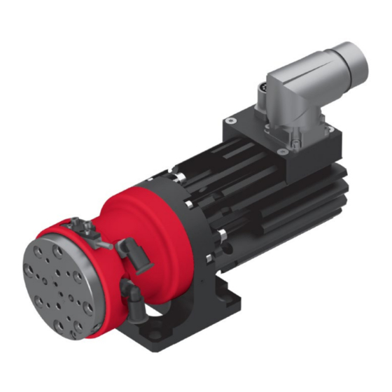
The rotational axis SE is a precision-engineered, highly compact electric axis for rotating payloads. Further technical information can be found in the chapter 3 Technical data in these installation instructions. 30 – 56 Assembly instructions EN SE20 - SE30 Date 06.09.2021 Version 2.0 ... -
Page 31: Installation, Assembly And Setting
2x Ø9h6 centring bushing + 4x screw M6x20 2x Ø7h6 centring bushing + 4x screw M4 2x Ø8h6 centring bushing + 4x screw M3 Fig. 8 Accessories (mounting material) Assembly instructions EN SE20 - SE30 Date 06.09.2021 Version 2.0 31–56 ... -
Page 32: Tightening Torques
Galvanized blue, oiled or greased Thread Tightening torque 1.1 … 1.4 Nm 2.6 … 3.3 Nm 5.2 … 6.5 Nm 9.0 … 11.3 Nm 21.6 … 27.3 Nm 32 – 56 Assembly instructions EN SE20 - SE30 Date 06.09.2021 Version 2.0 ... -
Page 33: Connection
17 kg Dimension (HxWxD) 125x62x121mm 230x66x177mm 275x280x165mm External fuse 6 A (C, D, K type) 16-32 A (C, D, K Type) 8 A (C, D, K type) Assembly instructions EN SE20 - SE30 Date 06.09.2021 Version 2.0 33–56 ... -
Page 34: Servo Controller
Installation, assembly and setting 6.3.2 Servo controller Fig. 10 Overview servo controller 34 – 56 Assembly instructions EN SE20 - SE30 Date 06.09.2021 Version 2.0 ... -
Page 35: Axis Controller C11X0
The controllers are pre-configured so that, as a rule, no software adjustments are necessary. If adjustments are to be made, the software "LinMot-Talk" can be obtained free of charge from the website"www.linmot.com". Assembly instructions EN SE20 - SE30 Date 06.09.2021 Version 2.0 35–56 ... -
Page 36: Fig. 11 Axis Controller C11X0
Safely disconnect the power supply unit (72V) on the primary side at the controller C11x0 or switch off the input "Safety Relay" (X33). 36 – 56 Assembly instructions EN SE20 - SE30 Date 06.09.2021 Version 2.0 ... -
Page 37: Axis Controller C12X0
The controllers are pre-configured so that, as a rule, no software adjustments are necessary. If adjustments are to be made, the software "LinMot-Talk" can be obtained free of charge from the website"www.linmot.com". Assembly instructions EN SE20 - SE30 Date 06.09.2021 Version 2.0 37–56 ... -
Page 38: Fig. 12 Axis Controller C12X0
Safely disconnect the power supply unit (72V) on the primary side at the controller C11x0 or switch off the input "Safety Relay" (X33). 38 – 56 Assembly instructions EN SE20 - SE30 Date 06.09.2021 Version 2.0 ... -
Page 39: Motor Connector
Installation, assembly and setting 6.3.5 Motor connector Combination (connector on axle) Combination (connector on controller) Y connector: Insert - Controller C11x0 XC - Controller C12x0 XC Assembly instructions EN SE20 - SE30 Date 06.09.2021 Version 2.0 39–56 ... -
Page 40: Pin Assignment (Encoder)
Free Free Clock- Green A+ / sin+ Black B+ / cos+ Z+ / Data+ blue Free Free Free Clock+ grey/pink Housing Screen outer screen 40 – 56 Assembly instructions EN SE20 - SE30 Date 06.09.2021 Version 2.0 ... -
Page 41: Programming
With the C1xx0 controller, the safety inputs X33 must be safely disconnected, or the power supply unit (72 V) must be disconnected on the primary side! Assembly instructions EN SE20 - SE30 Date 06.09.2021 Version 2.0 41–56 ... -
Page 42: Switching Distance - Reference Sensor For Electric Axes
The reference sensor of the rotational axes is mounted with a feeler gauge at a distance of 0.1 mm parallel to the switching lug. The positions can be found in the respective drawings (note the axle types). 42 – 56 Assembly instructions EN SE20 - SE30 Date 06.09.2021 Version 2.0 ... -
Page 43: Commissioning
5. Switch on the controller unit and check the correct function of the encoder and the reference switch. 6. Perform test run: Start with slow movements Subsequently under normal operating conditions Commissioning is completed. Assembly instructions EN SE20 - SE30 Date 06.09.2021 Version 2.0 43–56 ... -
Page 44: Fault Elimination
Module does not move necessary Carry out function check according to commissioning Motor disconnection Check motor cable Drive defective Have drive replaced by Afag 44 – 56 Assembly instructions EN SE20 - SE30 Date 06.09.2021 Version 2.0 ... -
Page 45: Maintenance And Repair
If the system is to be operated in an environment with abrasive dusts or corrosive or aggressive vapours, gases or liquids, the approval of Afag must be obtained in advance. Assembly instructions EN SE20 - SE30 Date 06.09.2021... -
Page 46: Overview Of The Maintenance Points
Do not use lubricants with additives such as MoS , graphite or PTFE. These lubricants can damage the module! Only use the lubricants recommended by Afag in the maintenance table chapter 9.3.1 or equivalent lubricants! 46 – 56 Assembly instructions EN SE20 - SE30 Date 06.09.2021... -
Page 47: Further Maintenance
Encoder Designation Article no. Connection cable 10m for E11x0 12-pin M12x1 - SubD 9pin 520.754 Connection cable 10m for B1100/C1xx0/E12x0 12-pin M12x1 - SubD 15pin 520.755 Assembly instructions EN SE20 - SE30 Date 06.09.2021 Version 2.0 47–56 ... -
Page 48: Motor Cable
Type K05-Y/R-8 080.683 9.5 Repair and overhaul Afag offers a reliable repair service. Defective modules can be sent to Afag for warranty repair within the warranty period. After expiry of the warranty period, the customer may replace or repair defective modules or wear parts himself or send them to the Afag repair service. -
Page 49: Decommissioning, Disassembly, Disposal
Electronic parts, electrical scrap, auxiliary and operating materials must be disposed of by approved specialist companies. Information on proper disposal can be obtained from the responsible local authorities. Assembly instructions EN SE20 - SE30 Date 06.09.2021 Version 2.0 49–56 ... -
Page 50: Declaration Of Incorporation
The relevant technical documentation was created according to Annex VII, Part B of the above-mentioned Directive. Authorised representative for compiling the technical documentation: Walter Kunz, Afag Engineering GmbH, Gewerbestraße 11, DE-78739 Hardt Place/Date: Hardt, 15.06.2021 Walter Kunz Managing Director Afag Engineering GmbH 50 –... - Page 51 Obligations and liability ........10 Storage ............. 29 Obligations of the operating company ....10 System error ............. 44 Obligations of the personnel ......11 Operation ............44 Assembly instructions EN SE20 - SE30 Date 06.09.2021 Version 2.0 51–56 ...
- Page 52 List of figures Fig. 1 Dimensional drawing rotational axis SE20-2 .................. 16 Fig. 2 Dimensional drawing - Rotational axis SE20-4 ................18 Fig. 3 Dimensional drawing - Rotational axis SE30-2 ................21 Fig. 4 Dimensional drawing - Rotational axis SE30-4 ................23 Fig.
- Page 53 Assembly instructions EN SE20 - SE30 Date 06.09.2021 Version 2.0 53–56 ...
- Page 54 54 – 56 Assembly instructions EN SE20 - SE30 Date 06.09.2021 Version 2.0 ...
- Page 55 Assembly instructions EN SE20 - SE30 Date 06.09.2021 Version 2.0 55–56 ...
- Page 56 56 – 56 Assembly instructions EN SE20 - SE30 Date 06.09.2021 Version 2.0 ...
Need help?
Do you have a question about the SE20 and is the answer not in the manual?
Questions and answers