Table of Contents
Advertisement
Quick Links
Advertisement
Table of Contents

Related Manuals for Crystal Mountain EVEREST ELITE Series


Summary of Contents for Crystal Mountain EVEREST ELITE Series
- Page 1 Service Manual (100-115VDC) EVEREST ELITE POU Water Cooler...
-
Page 2: Table Of Contents
Table of Contents SECTION1:Product Specification ......................... 1-1 SECTION2:Parts Listing and Exploded Views....................2-1 Everest Elite Series Parts Listing ......................2-1 Exploded Views ............................. 2-2 Product Dimensions ..........................2-6 Description of Product Model Number ...................... 2-8 SECTION3: Reservoir Removal........................3-1 SECTION4: Hot Tank Venting Procedure...................... -
Page 3: Section1:Product Specification
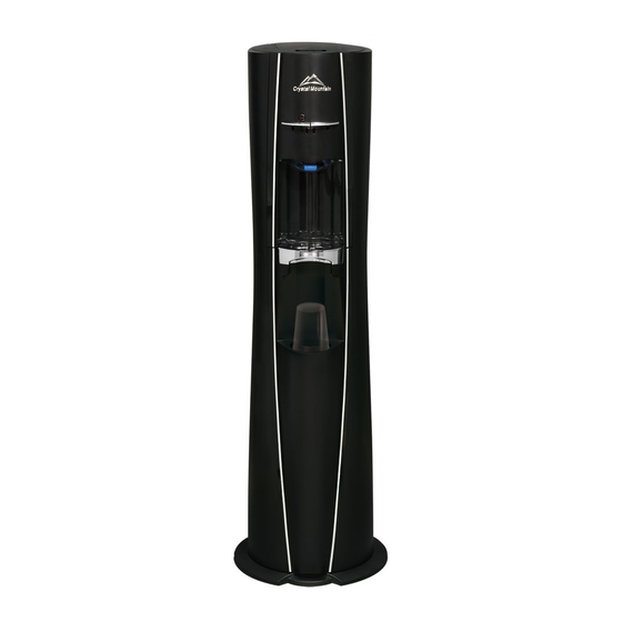
Product Specification EVEREST ELITE Inspired by the award winning Everest model, Crystal Mountain introduces the stunning Everest Elite. Innovative design features in- clude: removable side panels, double mechanical float, and raised faucet handles. It’s sleek design and upscale look is perfect for either home or office environments. - Page 4 115V EVEREST ELITE POU TYPE WATER COOLER DESCRIPTION PART CODE DESCRIPTION PART CODE Top Cover Assm - POU Everest SUB-C200250 B5 RED SILICONE DRAIN PLUG SIL-C100055 Lock Clip, EV POU PLC-C140038 B6 EVEREST HOT TANK DRAIN ASSM SUB-C200210 UPPER RESERVOIR SUPPORT PLC-C140019 B7 SPRING CLIP - 12MM FAS-C000029...
- Page 5 MODEL--ESEP2KHK1CC EVEREST ELITE POU WATER COOLER (WITH CUP DISPENSER)
- Page 6 MODEL--ESEP2KHK1NC EVEREST ELITE POU WATER COOLER (WITHOUT CUP DISPENSER)
- Page 7 EVEREST ELITE POU WATER COOLER (HOT TANK ASSMBLY, RESERVIOR ASSEMBLY, FAUCET ASSEMBLY and POU KIT ASSEMBLY )
- Page 8 EVEREST ELITE POU WATER COOLER...
- Page 9 11.0 inches inches 13.7 14.1 inches inches Front Side...
- Page 10 11.0 inches inches 13.5 14.1 inches inches Front Side...
-
Page 11: Description Of Product Model Number
Description of Product Model Number Cooler Shape Reservoir Type Type of Lid No. of Faucets Body Color Temp. Option Insert Color Voltage Optional P - POU Conversion Kit C – Cup K – Black H – Hot & Cold K – Black 1 –... -
Page 12: Section3: Reservoir Removal
SECTION 3: Reservoir Removal Notice: The information and/or procedures presented in the following demonstration(s) should be performed by a trained Water Cooler Service Technician only. Never attempt to service or repair a water cooler while it is plugged into any power supply. Prior to any service or repair of the water cooler, ensure that the water has been completely drained from the system. - Page 13 4. To remove faucet handles (using thumb and forefinger), reach inside top front of cooler and squeeze pivot clamp to release faucet handles (Figure 3-8 and Figure 3-9) and remove faucet han- dles (Figure 3-10 and Figure 3-11). Figure 3-8 Figure 3-9 Figure 3-10 Figure 3-11...
-
Page 14: Section4: Hot Tank Venting Procedure
SECTION 4: Hot Tank Venting Procedure Notice: The information and/or procedures presented in the following demonstration(s) should be performed by a trained Water Cooler Service Technician only. Never attempt to service or repair a water cooler while it is plugged into any power supply. Prior to any service or repair of the water cooler, ensure that the water has been completely drained from the system. -
Page 15: Section5: Cabinet-Panel Removal And Installation
SECTION 5: Cabinet - Panel Removal and Installation Notice: The information and/or procedures presented in the following demonstration(s) should be performed by a trained Water Cooler Service Technician only. Never attempt to service or repair a water cooler while it is plugged into any power supply. Prior to any service or repair of the water cooler, ensure that the water has been completely drained from the system. -
Page 16: Side Panel Removal
SECTION 5: Cabinet - Panel Removal and Installation Notice: The information and/or procedures presented in the following demonstration(s) should be performed by a trained Water Cooler Service Technician only. Never attempt to service or repair a water cooler while it is plugged into any power supply. Prior to any service or repair of the water cooler, ensure that the water has been completely drained from the system. - Page 17 Remove the 2 side panel installation screws from the back of the cooler (located mid way up the back panel) (Figure 5-2-5). Figure 5-2-5 Open the Top Cover by pressing the cover lock (Figure 5-2-6), and lifting the front of the Top Cover upwards (rotate upwards to rear of the cooler) (Figure 5-2-7).
-
Page 18: Side Panel Installation
SECTION 5: Cabinet - Panel Removal and Installation Notice: The information and/or procedures presented in the following demonstration(s) should be performed by a trained Water Cooler Service Technician only. Never attempt to service or repair a water cooler while it is plugged into any power supply. Prior to any service or repair of the water cooler, ensure that the water has been completely drained from the system. -
Page 19: Main Front Panel Removal & Installation
SECTION 5: Cabinet - Panel Removal and Installation Notice: The information and/or procedures presented in the following demonstration(s) should be performed by a trained Water Cooler Service Technician only. Never attempt to service or repair a water cooler while it is plugged into any power supply. Prior to any service or repair of the water cooler, ensure that the water has been completely drained from the system. -
Page 20: Section6: Electrical Component Diagnosis And Replacement
SECTION 6: Electrical Component Diagnosis and Replacement Notice: The information and/or procedures presented in the following demonstration(s) should be performed by a trained Water Cooler Service Technician only. Never attempt to service or repair a water cooler while it is plugged into any power supply. Prior to any service or repair of the water cooler, ensure that the water has been completely drained from the system. - Page 21 The heater band can be tested for resistance using a multi-meter set to 200 ¸ 4. Touch the two terminals on heater band with the sensor probes (Figure 6-1-5). The proper resis- tance is within a range of 28 to 32.2 ¸...
- Page 22 Models: Everest Elite Hot & Cold (110V)
-
Page 23: Cold Thermostat Removal And Installation
SECTION 6: Electrical Component Diagnosis and Replacement Notice: The information and/or procedures presented in the following demonstration(s) should be performed by a trained Water Cooler Service Technician only. Never attempt to service or repair a water cooler while it is plugged into any power supply. Prior to any service or repair of the water cooler, ensure that the water has been completely drained from the system. - Page 24 7. Cut the small plastic tie strap (holding Cold Thermostat Sensor to Evaporator Insulation) (Figure 6-2-8). Figure 6-2-8 8. Pull the sensor tube out from the Evaporator Insulation to remove (Figure 6-2-9). Note: If required, install the Sensor tube cover onto the replacement Cold Thermostat (Figure 6-2-10).
- Page 25 11. Reinstall the wires onto the Cold Thermostat (take care to ensure proper installation loca- tion)(Figure 6-2-14 to Figure 6-2-16). Figure 6-2-14 Figure 6-2-15 Figure 6-2-16 12. Insert bottom bracket into slot on back panel and slide downwards into position (Figure 6-2- 17).
-
Page 26: Cold Thermostat Adjustment
SECTION 6: Electrical Component Diagnosis and Replacement Notice: The information and/or procedures presented in the following demonstration(s) should be performed by a trained Water Cooler Service Technician only. Never attempt to service or repair a water cooler while it is plugged into any power supply. Prior to any service or repair of the water cooler, ensure that the water has been completely drained from the system. -
Page 27: Hot Tank Auto Cutout / Manual Reset Replacement
SECTION 6: Electrical Component Diagnosis and Replacement Notice: The information and/or procedures presented in the following demonstration(s) should be performed by a trained Water Cooler Service Technician only. Never attempt to service or repair a water cooler while it is plugged into any power supply. Prior to any service or repair of the water cooler, ensure that the water has been completely drained from the system. -
Page 28: Hot Tank Removal And Replacement
SECTION 6: Electrical Component Diagnosis and Replacement Notice: The information and/or procedures presented in the following demonstration(s) should be performed by a trained Water Cooler Service Technician only. Never attempt to service or repair a water cooler while it is plugged into any power supply. Prior to any service or repair of the water cooler, ensure that the water has been completely drained from the system. - Page 29 4. Pull the two wires that are connected to the heater band out through the silicone cover (Figure 6-5-11). Figure 6-5-11 5. Remove the single screw that secures the hot tank in place (Figure 6-5-12). Carefully slide the hot tank out from the bracket (Figure 6-5-13).
-
Page 30: Hot Tank Heater Band Replacement
SECTION 6: Electrical Component Diagnosis and Replacement Notice: The information and/or procedures presented in the following demonstration(s) should be performed by a trained Water Cooler Service Technician only. Never attempt to service or repair a water cooler while it is plugged into any power supply. Prior to any service or repair of the water cooler, ensure that the water has been completely drained from the system. -
Page 31: Compressor Relay / Overload Protector Replacement
SECTION 6: Electrical Component Diagnosis and Replacement Notice: The information and/or procedures presented in the following demonstration(s) should be performed by a trained Water Cooler Service Technician only. Never attempt to service or repair a water cooler while it is plugged into any power supply. Prior to any service or repair of the water cooler, ensure that the water has been completely drained from the system. -
Page 32: Section7:Cleaning And Sanitization
SECTION 7: Cleaning and Sanitization Notice: The information and/or procedures presented in the following demonstration(s) should be performed by a trained Water Cooler Service Technician only. Never attempt to service or repair a water cooler while it is plugged into any power supply. Prior to any service or repair of the water cooler, ensure that the water has been completely drained from the system. - Page 33 4. To drain the hot tank unscrew drain cap and remove red silicone plug at the rear of the cooler (Figure 7-6 and Figure 7-7) and drain water into a pail or container (approx 0.5 gallon or 1.8 L) (Figure 7-8). Rein- stall red silicone plug and drain cap.
- Page 34 7. Remove baffle assembly from the reservoir (Figure 7-15). Empty remaining water from reservoir (Figure 7-16). Figure 7-15 Figure 7-16 8. Remove faucet assembly by pulling away from reservoir (Figure 7-17). Figure 7-17 9. To remove the cold and hot faucet assemblies from the faucet outlet it is not required to remove the 2 screws.
- Page 35 10. Remove the two silicon faucet seals from the inlet end (Figure 7-21) and unscrew the faucet cap by rotating it counterclockwise to separate the top and bottom halves of the faucet assembly (Figure 7-22 and Figure 7-23). Figure 7-21 Figure 7-22 Figure 7-23 11.
- Page 36 13. Using the brush attachment, vacuum the condenser and all accessible areas to remove dirt, lint and debris (Figure 7-31 to Figure 7-39) (the use of the crevasse tool attachment may also be used). Use a scrub brush to remove dirt and debris from the condenser (Figure 7-35). Use an air hose to remove debris from inaccessible areas (do not exceed 100 PSI) (Figure 7-36 to Figure 7-38).
- Page 37 14. Electrical Diagnosis. Refer to Section 5 of the Service Manual; Electrical Component Diagnosis and Re- placement. 15. Reassemble the side panels and lower front panel by following step 12 in reverse order (Figure 7-47 to Figure 7-53). Note: the side panels go on prior to the lower front panel. Figure 7-47 Figure 7-48 Figure 7-49...
- Page 38 30 minutes to let the water cool and heat. Optimum water tempera- tures will be reached after several hours of operation. Figure 7-62 Crystal Mountain has a policy of continuous development and reserves the right to change specifications without notification. 7 - 7...
-
Page 39: Parts In Contact With Water
Parts in Contact with Water for Everest Elite POU Cooler FORMULATION MATERIAL SUPPLIER PART NO. PART DESCRIPTION MATERIAL TYPE D O C U M E N T C O N T R O L IN NUMBER & PIGMENT CODE SGS:GZ1111141736/CHEM PLC-C140035 FLOAT ARM, EV POU HI121H... -
Page 40: Section8: Product Standards
SECTION 8: Product Standards Item Title Standard No. Content Self-Contained,Mechanically-Refrigerated Drinking Water Performance standard ARI 1010 Coolers ANSI/ASHRAE Methods of Testing for Rating Drinking-Water Coolers with Methods of testing for coolers 18-2000 Self-contained Mechanical Refrigeration JIS C 9618-1992 Performance and method for coolers (in Japanese Drinking -Water Coolers Performance method) -
Page 41: Section9: Point Of Use Kit For Everest Elite Cooler
Point of Use Kit for Everest Elite Cooler With an Everest Elite Crystal Mountain Point Of Use Kit, an Everest Elite bottle cooler can be retrofitted to be- come a Point of Use dispenser as an alternative to bottled water. An air filter, incorporated into the top of the lid, protects the integrity of the water from airborne contaminants. - Page 42 Room 610, Winfield Commercial Building 6-8a Prat Avenue, Tsimshatsui Kowloon, Hong Kong Tel: (852) 2368 1989 Fax: (852) 3017 6727 E-mail: cmasia@crystalcoolers.com Website: www.crystalcoolers.com Crystal Mountain has a policy of continuous development and reserves the right to change specifications without notification. ESESM REV0316...
Need help?
Do you have a question about the EVEREST ELITE Series and is the answer not in the manual?
Questions and answers