Crystal Mountain Glacier Service Manual
Hide thumbs
Also See for Glacier:
- User manual (10 pages) ,
- Receiving, cleaning & operating instructions (12 pages)
Advertisement
Quick Links
Advertisement

Related Manuals for Crystal Mountain Glacier


Summary of Contents for Crystal Mountain Glacier
- Page 1 Service Manual (100-115VAC) GLACIER (Series Water Dispenser)
-
Page 2: Product Specification
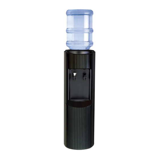
Product Specification GLACIER The rounded cabinet and fluted front give the Glacier a classic Greek column design. While being esthetically pleasing, the polyethylene cabinet’s smooth finish is easier to clean and refurbish. Featuring the patented DryGuard™ non-spill system, you’re protected from faulty or damaged water bottles. - Page 3 D Hot Tank System 115V GLACIER SERIES BOTTLED WATER COOLER (GLE/S RESERVOIR) E Refrigeration Replacement System *C Crystal Guard Assembly Note: 1. Parts may not appear exactly as shown. 2. Parts shown may not be present on all models.
- Page 4 Glacier cooler 314mm/12.4" 312mm/12.2"...
- Page 5 Reservoir Type Type of Lid No. of Faucets Body Color Temp. Option Insert Color Voltage GL – Glacier D – DryGuard 1 or 2 R – Granite H – Hot & Cold R – Granite 1 – 110-115 V G – Crystal Guard W –...
-
Page 6: Receiving Instructions
Receiving Instructions Inspect the cooler box for any evidence of shipping or handling damage. All shipping damage claims should be filed promptly with the carrier. Ensure cooler stands upright for 24 hours prior to use. Operating Instructions 1. Place the water cooler a minimum of 2 inches/ 5.3. - Page 7 Cleaning & Sanitisation Notice: The information and/or procedures presented in the following demonstration(s) should be performed by a trained Water Cooler Service Technician only. Never attempt to service or repair a water cooler while it is plugged into any power supply. Prior to any service or repair of the water cooler, ensure that the water has been completely drained from the system.
- Page 8 5. Add one and a half tablespoons of vinegar to 1 gallon (4.5 L) of clean water and pour into res- ervoir. Wipe the internal reservoir components, baffle cup and faucets with a clean cloth(fig.5-1) (fig.5-2). Let solution stand for five minutes. figure 5-1 figure 5-2 6.
- Page 9 6. Remove baffle cup(fig.6-1) and unscrew baffle stem and wing nut(fig.6-2)(fig.6-3). figure 6-1 figure 6-2 figure 6-3 7. Approach the cooler from the rear. Open the latch provided on the evaporator band (fig.7-1). figure 7-1 8. Use both hands to loosen the reservoir from the evaporator band and lift it straight through the cooler opening(fig.8-1).
-
Page 10: Removal And Installation
Removal and Installation Notice: The information and/or procedures presented in the following demonstration(s) should be performed by a trained Water Cooler Service Technician only. Never attempt to service or repair a water cooler while it is plugged into any power supply. Prior to any service or repair of the water cooler, ensure that the water has been completely drained from the system. - Page 11 5. Using the Crystal Guard removal tool (SMT-C000110) to insert clean pin in guard(fig.5-1). Twist the Crystal Pin clockwise until the four locking tabs are approximately half way between the four holes(fig.5-2). figure 5-1 figure 5-2 6. Insert the floater into the cylindrical toothed part on the backside of the Crystal Guard(fig.6-1). Note: Make sure that once installed, the floater can move freely up and down inside the cylinder.
- Page 12 9. Re-install the Crystal Guard onto cooler. The Crystal Guard system was designed to seal air and therefore the guard will fit very tightly when installed with the blue gasket(fig.9-1). figure 9-1 10. Poke the arrow pin used to lock the Crystal Guard down through its drilled hole to secure the lid on the cooler(fig.10-1).
- Page 13 . E & S Series Reservoir Removal Procedure 1. Remove the water bottle(fig.1-1) and drain water from the reservoir(fig.1-2) and hot tank, re- membering to cool and drain hot tank. Allow 2 hours for hot water to cool down inside the hot tank before removing the drain plug at the rear of the cooler to drain into a bucket.
- Page 14 4. Remove the baffle cup by lifting straight out(fig.4-1). Loosen & remove the baffle stem(fig.4-2) and wing nut(fig.4-3) by turning counterclockwise. figure 4-1 figure 4-2 figure 4-3 5. Approach the cooler from the rear. Open the latch provided on the evaporator band(fig.5-1). figure 5-1 6.
- Page 15 . DryGuard Removal & lnstallation Procedure REMOVAL 1. Remove the bottle (fig.1-1) and Outer DryGuard Cover (fig.1-2) from the cooler. figure 1-1 figure 1-2 2. Approaching the cooler from the side, place one palm onto the top of the cooler on the side fur- thest from you, and using your thumb, press downwards on the reservoir Insulation (fig.2-1).
- Page 16 5. Using the palms of both hands, push the DryGuard straight down into the reservoir (fig.5-1) (fig.5-2). figure 5-1 figure5-2 6. Install the Outer DryGuard Cover onto the cooler (fig.6-1) and lock into place by turning clock- wise (fig.6-2). figure 6-1 figure 6-2 5- 7...
- Page 17 . Refrigeration Repair System(RRS) Removal Procedure 1. Unplug cooler from power source (fig.1-1). 2. Empty and remove water bottle( fig.2-1 ) and drain cooler reservoir through the faucets until empty (fig.2-2) .If cooler is a hot and cold, the hot tank must be drained from the drain plug located on the back of unit on the lower right side( fig.2-3) .
- Page 18 5. If cooler is equipped with a white aluminum evaporator (cooling band), loosen (fig.5-1) and unhook (fig.5-2) the latch and catch from the band and pull the band back away from reservoir to- wards the back of cooler cabinet. If cooler is equipped with a copper tubing evaporator, there is no latch system to unhook.
- Page 19 9. The RRS system is now ready to be slid out of the plastic cabinet. 10. Hold the condenser on the right hand side and slowly lift and pull to free the RRS system from the cooler body. Slowly work the unit from top to bottom until it starts to slide out. Once it starts to come out, be careful of the small capillary tube (copper coil) located on the left side of the com- pressor as it is very fragile (fig.10-1) , guide it by the cooler body with your hand.
- Page 20 . Replacing Hot Tank Auto Cutout & Manual Reset Procedure Note: Begin with the unit unplugged, water drained and the refrigeration system removed from the cabinet. Tip: Use a small flathead screwdriver to pry wire connectors off. 1. Remove the wire connectors from the top and bottom of the thermostat to be changed and iden- tify (fig.1-1).Remove the two screws and remove the thermostat from the bracket (fig 1-2).
- Page 21 . Hot Tank & Heater Assembly Replacement Procedure Removal 1. Remove Refrigeration System (Refer to RRS Removal Procedure) 2. Stand the RRS system on a bench or table for easier access to components. 3. Remove drain assembly from condenser (black grill) at back of unit (fig.3-1) . figure 3-1 4.
- Page 22 7. Hold the hot tank assembly with one hand while removing the 2 screws that hold the hot tank support bracket on the back of the condenser (fig.7-1) . Lift the bottom reservoir insulation slightly and slide tank down and out.. figure 7-1 Installation 8.
- Page 23 . Replacing Compressor Relay & Overload Procedure Note: Begin with the unit unplugged, water drained and the refrigeration system removed from the cabinet. Tip: Use a small flathead screwdriver to pry wire connectors and relay from compressor. 1. Remove the relay/overload cover by prying the metal clip to unhook it from the compressor on both sides (fig 1-1 and 1-2).
- Page 24 . Hot Tank Heater Replacement Procedure 1. Remove Refrigeration System (Refer to RRS Removal Procedure). 2. Stand RRS system on bench or table for easier access to components (fig.2-1) . figure 2-1 3. Unplug wire connector from heater band that goes to the manual reset, which is mounted along with the auto cutout, in the bracket directly above the heater tightening screw (fig.3-1) .
-
Page 25: Troubleshooting
Trouble Shooting N o t i c e : N o t i c e : N o t i c e : N o t i c e : N o t i c e : The information and/or procedures presented in the following demonstration(s) should be performed by a trained Water Cooler Service Technician only. - Page 26 Problem Problem Problem Cause Cause Cause Repair Repair Repair Problem Problem Cause Cause Repair Repair 7. No hot or cold water e) air lock e) check floater in DryGuard to make sure it moves freely. check air filter, if wet remove and dry overnight.
- Page 27 Notice: The information and/or procedures presented in the following demonstration(s) should be performed by a trained Water Cooler Service Technician only. Never attempt to service or repair a water cooler while it is plugged into any power supply. Prior to any service or repair of the water cooler, ensure that the water has been completely drained from the system.
-
Page 30: Product Standards
Product Standards T i t l e T i t l e T i t l e T i t l e T i t l e C o n t e n t C o n t e n t Standard No. - Page 31 Gasket Outer DryGuard Creates a uniform, airtight seal cover around the inside diameter Float ring of the reservoir. in down position Normal water level Baffle stem Elbow nut Inner DryGuard cone Air Intake Float ring closed The air intake is closed off. Water lever overfills Crystal pin Baffle disk...
- Page 32 Winfield Commercial Building 6-8A Prat Avenue, Tsimshatsui Kowloon, Hong Kong Tel: (852) 2368 1989 Fax:(852) 3017 6727 E-mail: cmasia@crystalcoolers.com Website: www.crystalcoolers.com Crystal Mountain has a policy of continuous development and reserves the right to change specifications without notification. GLACIERSM REV0619...
Need help?
Do you have a question about the Glacier and is the answer not in the manual?
Questions and answers