Table of Contents

Related Manuals for Crystal Mountain STORM


Summary of Contents for Crystal Mountain STORM
- Page 1 Service Manual (220-240VDC) STORM (POU Water Cooler)
-
Page 2: Table Of Contents
Table of Contents SECTION1:Product Specification ......................... 1-1 SECTION2:Parts Listing and Exploded Views....................2-1 Storm Parts Listing ..........................2-1 Exploded Views ............................. 2-2 Product Dimensions ..........................2-5 Description of Product Model Number ...................... 2-6 SECTION3: Replacement of SmartFlo Water Cartridge ......................3-1 SECTION4: Install POU Water System ...................... -
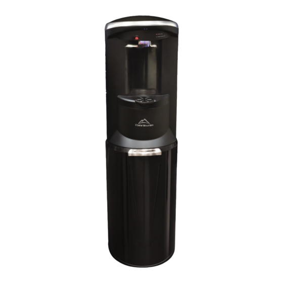
Page 3: Section1:Product Specification
Servicing has never been easier. With its contemporary design, attractive finish, concealed faucets and easy maintenance, the Storm is sure to dazzle in any envi- ronment. . High gloss finish, with stainless look and Sliding front door . - Page 4 220V Storm POU Water Cooler Parts Listing MODEL--STFP2KHK2C DESCRIPTION DESCRIPTION PART CODE PART CODE BACK PANEL, BLACK 220V HOT TANK + ELECTRICAL ASSEMBLY(INTERNAL 500W) PLC-C150002 SUB-C200252 220V POWER CORD, UK, BLACK SEAL, MANIFOLD INLET/OUTLET - OD18 X 11MM ELE-C100213 SIL-C120006...
-
Page 8: Product Dimensions
Product Dimensions Storm (POU Water Cooler) 2 - 5... -
Page 9: Description Of Product Model Number
Type of Lid No. of Faucets Body Color Temp. Option Insert Color Voltage Option ST – Storm P –Point Of Use K – Black H – Hot & Cold K – Black 2 – 220~240V C – Made in China F–... -
Page 10: Section3: Replacement Of Smartflo Water Cartridge
Replacement of SmartFlo™ Water Cartridge Notice: The information and/or procedures presented in the following demonstration(s) should be performed by a trained Water Cooler Service Technician only. Prior to any service or repair of the water cooler, ensure that the water has been completely drained from the system. For the best tasting and highest quality water, it is recommended to change the SmartFlo™... - Page 11 5. Insert the access key into the 2 holes located at the underside of the top edge of the cooler (above water levers) and push inwards (Figure 3-5 and Figure 3-6)(once unlocked, the front of the top cov- er opens upwards). Figure 3-5 Figure 3-6 6.
- Page 12 10. Insert water line of replacement SmartFlo™ Water Cartridge through the guide tube, and push through to bottle installation area (Figure 3-10). Figure 3-10 11. Ensure gasket/seal is properly installed on the outlet tube of the SmartFlo™ Water Cartridge as- sembly (may have shifted during shipment or un-packaging) (Figure 3-11).
- Page 13 16 . Remove protective cap from the SmartFlo™ water line and install onto the POU system (Figure 3-17 and Figure 3-18). Figure 3-17 Figure 3-18 17. Position POU system within the cooler (Figure 19), ensuring that the tubing is not kinked or locat- ed where it will interfere with the access door.
- Page 14 20. Open (Turn On ) the water supply to the POU system. 21. Depress the Cold or Hot water lever to fill the respective tanks (Figure 3-22 and Figure 3-23). When water begins to flow from both faucets, the tanks have been filled (approximately 1 minute per tank although it may be less time).
-
Page 15: Section4: Install Pou Water System
In order to satisfy plumbing regulations, a backflow preventer or check valve maybe required. Failure to use an appropriate anti-flood device for any reason will not obligate or make Crystal Mountain responsible in any way for Product Liability issues relating to any claims, including water damage claims. - Page 16 2) Use latex or nitrile gloves or wash hands before and after handling water contact parts. Remove cover assembly from the reservoir by pulling upwards (Figure 4-5 and Figure 4-6). Rinse cover assembly and reservoir with clean water and reassemble prior to installation into the frame assembly (Figure 4-7 and Figure 4-8).
- Page 17 Figure 4-17 Figure 4-18 3. Install POU system into cooler: a. Connect the bottle tube (within cooler) to the top of the POU system (Figure 4-19 to 4-21). Figure 4-19 Figure 4-20 Figure 4-21 b . Verify Indicator Position Ensure that float indicator is in the GREEN position after installation is complete (Figure 4-22).
- Page 18 4. Open (Turn On) the water supply to the POU system Allow the holding tank to fill prior to priming the water system on the Storm Water Dispenser. De- pending on the type of water treatment system installed, this may take several hours.
-
Page 19: Section5: Electrical Component Diagnosis And Replacement
SECTION 5 Electrical Component Diagnosis and Replacement Wiring and Schematics Models: Storm Hot & Cold water cooler... -
Page 20: Cold Thermostat Remove And Installation
Cold Thermostat Removal and Installation Notice: The information and/or procedures presented in the following demonstration(s) should be performed by a trained Water Cooler Service Technician only. Never attempt to service or repair a water cooler while it is plugged into any power supply. Prior to any service or repair of the water cooler, ensure that the water has been completely drained from the system. - Page 21 6. Cut the small plastic tie strap (holding cold thermostat sensor to evaporator insulation)(Figure 5-2-8). Figure 5-2-8 7. Pull the sensor tube out from the Evaporator Insulation to remove (Figure 5-2-9). Note: If required, install the Sensor tube cover onto the replacement cold thermostat. Figure 5-2-9 8.
-
Page 22: Cold Thermostat Adjustment
Cold Thermostat Adjustment Note: The cold thermostat can be adjusted without removal of any panel. Adjustment screw is on the back top side (when viewed from the back of the cooler, see Figure 5-3-1). Factory Setting: 6:00 Note: To identify the 6:00 setting position, rotate the set screw clockwise until it has stopped (screw should turn with light pressure, do not force). -
Page 23: Hot Tank Auto Cutout/Manual Reset Replacement
Hot Tank Auto Cutout/Manual Reset Replacement Notice: The information and/or procedures presented in the following demonstration(s) should be performed by a trained Water Cooler Service Technician only. Never attempt to service or repair a water cooler while it is plugged into any power supply. Prior to any service or repair of the water cooler, ensure that the water has been completely drained from the system. -
Page 24: Hot Tank Removal And Replacement
Hot Tank Removal and Replacement Notice: The information and/or procedures presented in the following demonstration(s) should be performed by a trained Water Cooler Service Technician only. Never attempt to service or repair a water cooler while it is plugged into any power supply. Prior to any service or repair of the water cooler, ensure that the water has been completely drained from the system. - Page 25 4. Relax and remove the spring clip by using a plier (Figure 5-5-10). Remove the drain hose from hot tank , if necessary. Note: Hose may be difficult to remove. If necessary, use a flathead screwdriver to slide up between the tube and pipe to release the hoses.
- Page 26 9. Plug the cooler back into power outlet. Push hot safety button and press the hot water faucet lever until water comes out (Figure 5-5-15). CAUTION: TO PREVENT DAMAGE TO THE HOT TANK, DO NOT SWITCH ON IF THE HOT TANK IS EMPTY.
-
Page 27: Compressor Relay / Overload Protector Replacement
Compressor Relay / Overload Protector Replacement Notice: The information and/or procedures presented in the following demonstration(s) should be performed by a trained Water Cooler Service Technician only. Never attempt to service or repair a water cooler while it is plugged into any power supply. Prior to any service or repair of the water cooler, ensure that the water has been completely drained from the system. - Page 28 4. Reinstall the cover (Figure 5-6-12) and secure with the metal clip (Figure 5-6-13). Note: use cau- tion not to damage wires. Figure 5-6-12 Figure 5-6-13 5 - 10...
-
Page 29: Section6:Trouble Shooting
Trouble Shooting Notice: The information and/or procedures presented in the following demonstration(s) should be performed by a trained Water Cooler Service Technician only. Never attempt to service or repair a water cooler while it is plugged into any power supply. Prior to any service or repair of the water cooler, ensure that the water has been completely drained from the system. - Page 30 Cleaning and Sanitization Notice: The information and/or procedures presented in the following demonstration(s) should be performed by a trained Water Cooler Service Technician only. Never attempt to service or repair a water cooler while it is plugged into any power supply. Prior to any service or repair of the water cooler, ensure that the water has been completely drained from the system.
- Page 31 5. Use top cover key (an accessory of cooler, Figure 7-7), insert into the two holes (on the front top, at approx 2 inch above and to the right of hot water safety button) towards the cooler, push key to open top cover (Figure 7-8 and Figure 7-9).
- Page 32 8. It is recommended that the hot tank be descaled periodically (frequency varies by mineral content). Only the use of descaling agents that are compatible with 304 grade stainless steel are recommended. The use of the descaling agents must be in accordance with the manufacturer’s safety instructions and recommendations and performed by properly trained personnel.
- Page 33 12. Reinstall or install a new SmartFlo™ Water Cartridge. Install the connector and corrugated tube into the inlet through cooler to bottom (Figure 7-26 and Figure 7-27). Insert the reservoir into evaporator (Figure 7-28). Ensure the SmartFlo™ Water Cartridge is installed properly. Turn the 2 knob to lock the SmartFlo™ Water Cartridge (Figure 7-29 and Figure 7-30).
- Page 34 16. Lift the door to open properly. Turn the hot tank power switch ON. Slide downwards to close the door. CAUTION: TO PREVENT DAMAGE TO THE HOT TANK, DO NOT SWITCH ON IF HOT TANK IS EMPTY. Crystal Mountain has a policy of continuous development and reserves the right to change specifications without notification. 7 - 5...
- Page 35 Room 610, Winfield Commercial Building 6-8a Prat Avenue, Tsimshatsui Kowloon, Hong Kong Tel: (852) 2368 1989 Fax: (852) 3017 6727 E-mail: cmasia@crystalcoolers.com Website: www.crystalcoolers.com Crystal Mountain has a policy of continuous development and reserves the right to change specifications without notification. STPOUSM REV0420...
Need help?
Do you have a question about the STORM and is the answer not in the manual?
Questions and answers
cold water will not completely shut off
The issue of cold water not completely shutting off may be caused by a faulty or misaligned SmartFlo SF-1 water cartridge or a problem with the pinch tube or valve assembly. To fix this issue:
1. Check the SmartFlo SF-1 Water Cartridge – Ensure it is properly installed and seated correctly. If necessary, remove and reinstall it.
2. Inspect the Pinch Tube and Valve Assembly – Look for any blockages, misalignment, or damage that may prevent proper sealing.
3. Ensure Proper Bottle Installation – Verify that the bottle adaptor assembly is securely connected to the water bottle.
4. Reset the System – Unplug the cooler, wait a few minutes, then plug it back in to reset any electronic components.
If the problem persists, the pinch tube or valve assembly may need to be replaced.
This answer is automatically generated
Any way to increase the rate of flow when filling cup?