
Related Manuals for GARO ATLE


Summary of Contents for GARO ATLE
- Page 1 GARO Atle Quick Start GARO AB Box 203, SE–335 25 Gnosjö Phone: +46 (0) 370 33 28 00 info@garo.se garo.se...
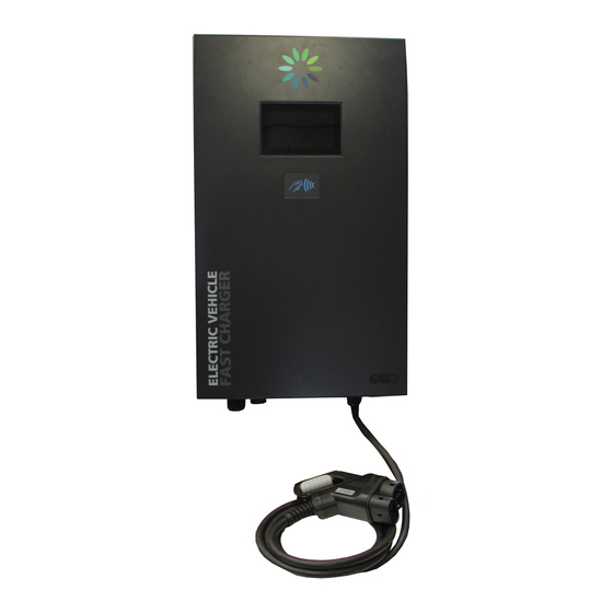
- Page 2 ATLE CCS or CHAdeMO Antennas 7” touchscreen display RFID reader Emergency Stop button Input cable Output cable Key locker Connector support Output DC connector ATLE CCS + CHAdeMO 1. Antennas 2. 7” touchscreen display 3. RFID reader 4. Connector support 5.
- Page 3 Internal view Optionnal modem board RFID reader board Modem board Display board OCPP board 1. Antennas 2. External fans for heat exchanger 3. Hood stand 4. Key locker 5. Input plate + cable gland 6. Emergency stop button 7. Heat exchanger 8.
- Page 4 Internal view - lower level ATLE CCS or CHAdeMO 1. Antennas 2. External fans for heat exchanger 3. Hood stand 4. AC input configuration board 5. Key locker 6. Input plate + cable gland 7. Emergency stop button 8. Heat exchanger 9.
- Page 5 Compliance Derating As a direct correlation exists between the current and ambient temperature a derating curve is provided for all charging station. Minutes before derating @ VOUT=370VDC & IOUT=65A...
- Page 6 INSTALLATIONS It is advisable to leave 1000mm free space on each side and 500mm on the top and the bottom of the chargingstation if it is surrounded by a wall. This free space is mandatory for charging station’s ventilation. Never block the air flow.
- Page 7 WARRANTY CONDITIONS EU COUNTRIES (EXCEPT SWEDEN) The product benefits from manufacturer´s warranty. The applicable warranty period must be stated in purchase documents from your supplier. The product must be installed by a certified installer / contractor. Proper installation, storage and operation conditions must be obtained. Warranties apply only to products installed in their original installation location.
-
Page 8: Table Of Contents
WALLBOX INSTALLATION GUN HOLDER INSTALLATION GARO ATLE CCS OR CHADEMO GARO ATLE CCS + CHADEMO ELECTRICAL CONNECTION AC INPUT CONFIGURATION ELECTRICAL CONNECTION GARO ATLE CCS OR CHADEMO ELECTRICAL CONNECTION GARO ATLE CCS + CHADEMO COMMISSIONING OPERATING INSTRUCTIONS UTILIZATION ERRORS PROTECTING THE ENVIRONMENT... -
Page 9: Information
• GARO ATLE CCS + CHAdeMO or its content. GARO does not grant any right or license for the • GARO ATLE CCS + CHAdeMO + AC personal and noncommercial use of the document or its content, •... -
Page 10: Safety Notes
SAFETY NOTES Read these instructions carefully, and look at the equipment Do not use this product if the enclosure or the Electrical to become familiar with the device before trying to install, Vehicle Supply Equipment (EVSE) connectors are broken, operate, or maintain it. The following special messages may cracked, opened or shows any other indication of appear throughout this documentation or on the equipment to damage. -
Page 11: Specification
SPECIFICATION Main supply Mains supplies 3-phase P1/P2/P3 + N + GND 3x400V Mains 3-phase voltage range 400 V ± 10% Earthed electrical system TT or TN Frequency range 50 Hz ± 10% Nominal input current 40-37 A Maximum input current 45 A Power Factor 0,99... -
Page 12: Technical Specification
Permanent mounting Car Plug connector Plug #1 Plug #2 CHAdeMO Output cable length 3,50 Meters AC output for GARO ATLE CCS + CHAdeMO + AC only AC output AC Output voltage 400 V ± 10% AC _ AC Output current _max... - Page 13 Climatic & Environment constraints Operating temperature (with derating) -25°C to +55°C Storage temperature -25°C to +60°C Relative humidity 10% to 95% Installation altitude 2 000 m Internal DC output protection Hardware and software short circuit protection Software and Hardware over voltage protection adjustable +10% max Over temperature protection...
- Page 14 Radio Frequency characteristics The equipment module is designed to provide customers with global network coverage on the connectivity of UMTS/HSPA+, and it is also fully backward compatible with the existing EDGE and GSM/GPRS networks. Connectivity GSM/GPRS UMTS/HSPA+ Frequency Bands GSM900: Tx=880 MHz to 915MHz, 3G band 8: Tx=880 MHz to 915MHz, Rx=925 MHz to 960 MHz / Rx=925 MHz to 960 MHz /...
- Page 15 Norms & standards Electric vehicle conductive charging system part 22 IEC 61851-22 AC Electric vehicle charging station Electric vehicle conductive charging system part 23 IEC 61851-23 DC Electric vehicle charging station Electromagnetic compatibility (EMC) EN 61000-6-2 EN 61000-6-4/A1 EN 301489 v2.2.0 EN 301489-17 V3.2.0 of 2017 EN 61000-3-11 EN 61000-3-12...
-
Page 16: Handling And Storage Instructions
Improper storage or handling may cause damage to the unit. Equipment Handling Failure to follow these instructions can result in equipment GARO ATLE CCS or CHAdeMO charging station is a 66kg damage. equipment, GARO ATLE CCS + CHAdeMO 93 kg. It must be handled by two people minimum. -
Page 17: Unpacking
UNPACKING 1. Remove the brackets holding the lid in place and lift the lid and sidewalls upwards. 2. Remove the lid of crate. You will use it to put the charging station. 3. Remove the T30 screw (x1) to remove the side panel. 4. -
Page 18: Garo Atle Ccs Or Chademo
GARO ATLE CCS or CHAdeMO GARO ATLE CCS + CHAdeMO 7a. Remove the charging station from its bracket. Note: Charging station must be handled by two people minimum. 7b. Remove the charging station from its bracket Note: Charging station must be handled with lifting... -
Page 19: Wallbox Installation
WALLBOX INSTALLATION For mounting the wallbox on a pedestal see separate installation manuals DIM016055 (GARO ATLE CCS or CHAdeMO) or DIM016197 (GARO ATLE CCS + CHAdeMO). For wall mounting follow the instructions below. Wall mounting Drill bit for M6 screws / anchors for M6 screws (x8) / drill / spirit level / chalk 1. -
Page 20: Gun Holder Installation
GUN HOLDER INSTALLATION Wallbox mounting 1. Clean the surface with isopropyl alcohol. 2. Wipe the surface with a clean cloth. 4. Screw by hand the positioning pins FXVIS018322 (x2) 3. Leave to dry 1min. 5. Peel the adhesive protection on the gun holder bracket. 8. -
Page 21: Garo Atle Ccs Or Chademo
12. Place the gun holder on its bracket, aligned with its studs. 13. Fix the gun holder with its M8 nuts (x4) GARO ATLE CCS + CHAdeMO GARO ATLE CCS or CHAdeMO 14b. Place the DC output connector onto the gun holder. -
Page 22: Electrical Connection
ELECTRICAL CONNECTION ELECTRICAL CONNECTION GARO ATLE CCS or CHAdeMO Checking the Electrical Requirements 1. Access to external circuit breaker. The DC Fast Charger electric requirements and wiring installation 2. Switch off the power at the main breaker panel. procedure should be performed by a qualified electrician. - Page 23 8a 3-phase P1/P2/P3 + N + GND (3x380-480V The connecting point of the unit shall be protected by: 6. Remove the screws (x8) holding input plate with • a 50A tetrapolar MCB (C-curve or equivalent), the cable gland. • a 30mA Type A or B RCD. Wiring must be at: •...
-
Page 24: Electrical Connection Garo Atle Ccs + Chademo
14. Turn the mains circuit breaker power on. Note: Charging station is now powered. It will startup, perform a self-test and will display on its screen when ready to use. ELECTRICAL CONNECTION GARO ATLE CCS + CHAdeMO 1. Access to external circuit breaker. - Page 25 6. Remove 15mm of insulation from the end of the power cable to be connected to the internal circuit breaker. 5. Pass the power cable through the input cablegland into the housing. 7. Connect ground wire to connection terminal block. 8.
- Page 26 GARO ATLE CCS + CHAdeMO + AC (3-phase P1/P2/P3 + N + GARO ATLE CCS + CHAdeMO (3-phase P1/P2/P3 + N + GND GND 3x400V 3x400V The connecting point of the unit shall be protected by: The connecting point of the unit shall be protected by: •...
- Page 27 11. Close the door. 12. Lock the door (1 keylock). Switch on external power supply 13. Access the external mains circuit breaker. 14. Turn the mains circuit breaker power on. Note: Charging station is now powered. It will startup, perform a self-test and will display on its screen when ready to use.
-
Page 28: Commissioning
COMMISSIONING SIM Card GARO Atle is either sold as a stand-alone wallbox or is connected to a backend operator via OCPP. The connection is carried out via mobile network (3G/4G) via one of the two modems included in the wallbox. The configuration of the wallbox is performed before delivery if the wallbox is ordered with a backend connection. - Page 29 First booting During the first power up of the charging station, the following messages will appear on-screen: If the display does not turn on during power up, please see the maintenance manual. After booting, check that the charging station is connected on the backend server. If not, please see the maintenance manual. Booting errors Message Description...
-
Page 30: Operating Instructions
OPERATING INSTRUCTIONS Emergency Stop Start a Vehicle Charge Session In the event of an emergency the Emergency Stop button may be depressed to instantly stop charging. To emergency stop follow these steps: Before starting a charge session: 1. Depress the emergency stop button bellow the charger Ensure the unit is properly assembled in accordance with the assembly instructions before it is used. - Page 31 Charge Selection User identification Depending on your configuration, the Wallbox offers up to 3 Once the type of charge selected, an identification screen is means of connection to the vehicle. displayed. When an user wants to recharge the electrical vehicle, there are 2 ways to identify on the charging station: •...
- Page 32 EV communication EV charge Before starting a charge, the charging station communicates with CCS or CHAdeMO the electrical vehicle to collect information. All these steps are necessary to adapt the charging station During the charge of the electrical vehicle, the charging station parameters to the electrical vehicle.
- Page 33 End of charge After completing the charge of the electric vehicle, the charging station performs multiple control steps before disconnecting the vehicle. CHAdeMO When the CCS protocol is used, the user can unplug the vehicle When the CHAdeMO protocol is used, the user must press the red once the charge is done.
- Page 34 Link established. Waiting for car’s start command... GARO ATLE CCS + CHAdeMO + AC only: This screen can be displayed when the user is using AC charging. The vehicle decides when to start charging. Plug your vehicle to start charging.
- Page 35 Message Description Remote reset started... Station will reboot now. Station is being rebooted. Station rebooted. Please unplug your vehicle. CCS only: Station rebooted during a charge. Please unplug and retry to launch the charge. Warning: insulation failure. Cable insulation failed. Please contact support.
-
Page 36: Errors
ERRORS The error messages are displayed with a characteristic screen. They are thus easily identifiable by the user. A warning pictogram is displayed along with the error message as shown below. The table below list errors messages who appears on the screen. Error Error resolution Error occurred: 0x02 - 0X03 - 0X81... - Page 37 Error Error resolution Error occurred: 0x22 CHAdeMO only: The connector cannot lock. Please The connector cannot lock. Please keep the connector closely keep the connector closely leant against your vehicle leant against your vehicle when plugging, when plugging, until the charge has started. Please until the charge has started.
-
Page 38: Protecting The Environment
PROTECTING THE ENVIRONMENT Recycling Packaging The packaging materials from this equipment can be recycled. Please help protect the environment by recycling them in appropriate containers. Thank you for playing your part in protecting the environment. End-of-Life Recycling This product has been optimized to reduce the amount of waste produced at the end of their useful life and for better recovery of component parts and materials when following customary processing procedures.
Need help?
Do you have a question about the ATLE and is the answer not in the manual?
Questions and answers