GARO GLB Assembly And User Instructions Manual
Wallbox
Hide thumbs
Also See for GLB:
- Quick start manual (13 pages) ,
- Assembly instructions manual (41 pages) ,
- Quick start manual (15 pages)
Table of Contents
Advertisement
Advertisement
Table of Contents

Related Manuals for GARO GLB


Summary of Contents for GARO GLB
- Page 1 GARO GLB Wallbox 380177-2 Assembly instructions / Instructions of use (EN)
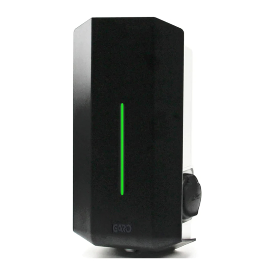
- Page 2 GARO GLB Wallbox GARO GLB Wallbox with cable and connector, type 1 or 2 with type 2 socket (figure 1) Front cover Cover (figure 3) Base box Indication light Connector type 1 or 2 Type 2 socket Personal protective circuit breaker, residual-current circuit breaker and energy (figure 2) meter, if required.
-
Page 3: Table Of Contents
TABLE OF CONTENTS GLB Wi-Fi Master About this manual Connecting to the wallbox's Wi-Fi access point (AP) Web interface Assembly instructions for fitters Scheduled charging Contents of the box Limit charging current Step by step Installation Connect charger to a local network via Wi-Fi Reducing the charging current –... -
Page 4: About This Manual
GARO Wallbox. This document contains general descriptions which have been verified for their accuracy at the time of printing. However, as GARO is committed to the pursuit of continuous improvement, we reserve the right to make changes to products if required. -
Page 5: Assembly Instructions For Fitters
1 2 3 4 5 6 Congratulations on selecting a GARO Wallbox and contributing to a better environment. E-Meter GK32 The GARO Wallbox is an AC charger enabling Mode 3 charging which complies fully Ext. charge control Remote control open=on, close=off... -
Page 6: Contents Of The Box
Assembly instructions for fitters / Contents of the box Contents of the box Drill template GBL Wallbox (see the back of the box) GARO Wallbox 380175-3 Assembly instructions/User Instructions (EN) Keys Manual Language labels... -
Page 7: Step By Step Installation
Assembly instructions for fitters / Step by step Installation Assembly instructions for fitters / Step by step Installation Step by step Installation Ensure the supply cable is not live. Remove the drill template from the packaging. Attach the drill template to the wall where the charger will be installed. Suitable height (see Technical data on page 45) Drill/mark in accordance with the instructions on the drill template. - Page 8 Assembly instructions for fitters / Step by step Installation Serial no./SSID password For incoming single-phase supply (Wi-Fi version only) (16A, 240V or 32A, 240V) on a three-phase GLB, the incoming phase is channelled to connection block L1. language labels RCCB are placed on the side 30mA INC.
- Page 9 Assembly instructions for fitters / Step by step Installation Assembly instructions for fitters / Step by step Installation (figure 9) (figure 10) Re-install the front cover by feeding it in from below. Connect the power and ensure the indication light is constantly green. Lock the front cover with the key.
-
Page 10: Reducing The Charging Current - Switch 2
Assembly instructions for fitters / Reducing the charging current – Switch 2 Assembly instructions for fitters/ Remote control of charger via enable port Reducing the charging current – Switch 2 Remote control of charger via enable port Depending on the size of the fuse, overload may occur, primarily at the property's meter The wallbox is equipped with a port, where charging can be activated and deactivated. -
Page 11: Load Balancing For Individual Chargers
Load balancing for individual chargers Setting the amperage for main fuses To activate load balancing, a GARO Modbus energy meter must be installed in the During installation, the amperage of the DIP switch SW1(1-2-3) must be adjusted to supply distribution box. The following energy meters are approved: correspond with the size and strength of the main fuses. -
Page 12: Load Balancing For Multiple Chargers In Group
Assembly instructions for fitters / Load balancing for multiple chargers in group Load balancing for multiple chargers in group To activate load balancing in a group, a GARO Modbus energy meter must be installed Example of installation – Data Link, direct connection between wallboxes in the supply distribution box. -
Page 13: Load Balancing Settings In The Web Interface
Assembly instructions for fitters / Load balancing settings in the web interface Assembly instructions for fitters / Load balancing settings in the web interface Load balancing settings in the web interface Wi-Fi version only All load balancing settings in groups are carried out via the wallbox's web interface. To connect a mobile phone, tablet or computer to the wallbox, see the section entitled Connecting to a Wi-Fi access point (AP). - Page 14 Assembly instructions for fitters / Load balancing settings in the web interface Assembly instructions for fitters / Load balancing settings in the web interface (figure 19) (figure 20) Select current or power limitation Set maximum current (A) or power (kWh) In the case of a single-phase charger, if the charger is to be controlled by load balancing, the phase assignation must be set.
-
Page 15: Instructions For Users
Instructions for users / Charging e-vehicles Instructions for users / Charging e-vehicles INSTRUCTIONS FOR USERS Charging e-vehicles Connect the wallbox to the vehicle using the cable. Charging commenced, blue light indicates charging in progress. Stop charging. As a rule, the wallbox socket and vehicle inlet lock the cable. As a result, charging must be stopped before the cable is removed from the vehicle. -
Page 16: Resetting/Relocation
Instructions / Resetting/Relocation Instructions / Resetting/Relocation Resetting/Relocation the residual-current or personal protective current breaker The wallbox is equipped with a personal protective circuit breaker (single-phase) or residual-current circuit breaker (three-phase) (H). In the event of overload/earth fault, these can be tripped. These components must also be conditioned once or twice a year, depending on the environment. -
Page 17: Glb Wi-Fi Master
GLB WIFI Master / Connecting to the wallbox's Wi-Fi access point GLB WIFI Master / Connecting to the wallbox's Wi-Fi access point GLB WI-FI MASTER Connecting to the wallbox's Wi-Fi access point (AP) Check that the wallbox is live. Check the Serial no./SSID and password on the label which can be found on the wallbox's sliding cover. -
Page 18: Web Interface
GLB Wi-Fi Master / Web interface GLB Wi-Fi Master / Web interface Web interface To gain access to the wallbox's web interface it must be connected to the same network as a mobile phone, tablet or computer. See the section entitled Connecting to the wallbox's Wi-Fi access point (AP). -
Page 19: Scheduled Charging
GLB WIFI Master / Scheduled charging GLB WIFI Master / Scheduled charging Scheduled charging This feature enables the user to schedule the days and times when the wallbox is accessible. Select scheduled control. Select the day and start/stop time. Click ‘Book’. - Page 20 GLB WIFI Master / Scheduled charging GLB WIFI Master / Scheduled charging (figure 28) (figure 29) Chart showing energy consumption over time. Information about charger. Choice of year and month for chart to display. Limitation of charging current. See section entitled Limiting charging current.
-
Page 21: Limit Charging Current
GLB WIFI Master / Limit charging current GLB WIFI Master / Connect charger to a local network via Wi-Fi Limit charging current Connect charger to a local network via Wi-Fi The charging current can be temporarily reduced during a specific period via the web The wallbox will attempt to connect to the specified Wi-Fi network. - Page 22 GLB WIFI Master / Connect charger to a local network via Wi-Fi Enter the serial no./SSID and password appearing on the label on the cover. Launch chargebox.garo.se in your browser. (figure 32)
-
Page 23: Activating Rfid
GLB WIFI Master / Activating/Deactivating RFID GLB WIFI Master / Activating/Deactivating RFID Activating RFID To activate the RFID reader, check the box labelled ‘Request RFID when connecting’ and click ‘Save’. Deactivating RFID To deactivate the RFID reader, un-check the box labelled ‘Request RFID when connecting’... -
Page 24: Activating Rfid Tags
GLB WIFI Master / Activating/Deleting RFID tags GLB WIFI Master / Activating/Deleting RFID tags Activating RFID tags When RFID is activated, you can choose to ‘Add a new tag’. You can now manually register the tag number in the ‘RFID Number’ field, and then click ‘Save’. Alternatively, you can read the tag number by selecting ‘Read tag from wallbox’. -
Page 25: Troubleshooting
Indication Type of fault Measure Constant red light The residual-current or Reset. Refer to section on Installation: on wall or Garo Wallbox stand personal protective current Resetting the residual-current Voltage rating: 230V/400 50Hz breaker or personal protective current Installation systems: TT, TN and IT systems has been tripped. -
Page 26: Dimensional Drawing
Dimensional drawing Dimensional drawing (figure 33) - Page 27 GARO AB Box 203, SE–335 25 Gnosjö Phone: +46 (0) 370 33 28 00 Fax: +46 (0) 370 33 28 50 info@garo.se garo.se...
Need help?
Do you have a question about the GLB and is the answer not in the manual?
Questions and answers