Table of Contents
Advertisement
Quick Links
- 1 Installation Instructions
- 2 Remote Control Function
- 3 Lan Connection Via Rj45 Port on Communication Card (Only for Glb-Wallbox with Communication Card Installed)
- 4 Connecting to the Wallbox's Wi-Fi Access Point (Ap)
- 5 Web Interface
- 6 Connect Glb-Wallbox to a Local Network Via Wi-Fi
- 7 Firmware Update for Glb Wallbox Not Connected to Internet Via Wifi or Lan
- 8 Troubleshooting
- Download this manual
Advertisement
Table of Contents

Related Manuals for GARO Wallbox GLB Series


Summary of Contents for GARO Wallbox GLB Series
- Page 1 GARO Wallbox GLB Assembly instructions / End User Instruction (EN)
-
Page 2: Table Of Contents
TABLE OF CONTENT About this manual Safety Information Installation Instructions Box Contents Tools and Materials Required Step-by-Step Guide Remote Control function Dynamic Load Management (DLM) for Stand-Alone GLB-Wallbox Dynamic Load Management (DLM) for GLB-Wallboxes in group Installing the RFID reader RFID for multiple GLB-Wallboxes in group LAN connection via RJ45 port on communication card (only for GLB-Wallbox with communication card installed) 28 Mainboard simplified connection diagram... -
Page 3: About This Manual
Garo Wallbox, model GLB This document contains general descriptions which are verified to be accurate at the time of printing. However, because continuous improvement is a goal at GARO, we reserve the right to make product modifications at any time. - Page 4 Do not install or use the GLB Wallbox near flammable, explosive, harsh, or combustible materials, chemicals, or vapors. Turn off input power at the circuit breaker before installing, configuring or cleaning of the GLB Wallbox. Use the GLB Wallbox only within the specified operating parameters. Never spray water or any other liquid directly at the GLB Wallbox.
- Page 5 Unroll the charging cable to prevent it from overheating. Do not use cleaning solvents to clean any of the GLB Wallbox’s components. The outside of the GLB Wallbox, the charging cable, and the end of the charging cable should be periodically wiped with a clean, dry cloth to remove accumulation of dirt and dust.
-
Page 6: Installation Instructions
Installation Instructions INSTALLATION INSTRUCTIONS Mandatory: Supply cable, 1-phase or 3-phase depending on GLB model Cable entrance from bottom side Custom (only when extra functions in use): • Twisted pair cable for Modbus energy meter • Twisted pair cable for Datalink communication •... -
Page 7: Box Contents
Installation Instructions Box Contents Drill template GLB Wallbox (see the back of the box) GARO Wallbox 380175-3 Assembly instructions/User Instructions (EN) Keys Manual Language labels... -
Page 8: Tools And Materials Required
IEC 61851-1 and IEC TS 61439-7. The product complies with IP Code IP44, with a closed front. It is to be fitted to a wall or GARO Wallbox stand, and all installation must be carried out by an authorized installer and comply with local country installation regulations. - Page 9 Installation Instructions GLB Laddstation tabell Protection type GLB Type GLB..-..37.. 2) 4) GLB..-..74.. 2) 4) GLB..-..22.. 1) 2) GLB..-..22..-A 2) 3) GLB..-..22..-B GLBDC..-..37.. GLBDC..-..74.. GLBDC..-..11.. GLBDC..-..22.. GLBDC..-..22..-A (figure 2) Chargers without RCCB or RCBO included in the enclosure must have Residual Current protection and must be protected with a max 32A fuse in the supply distribution box.
-
Page 10: Step-By-Step Guide
Installation Instructions Step-by-Step Guide Read Safety information. The installation must be carried out by an authorized installer. Select the appropriate group fuse (1x16A - 3x32A) and cable area for the electrical installation. Some countries require earth fault breakers to be installed. Follow local country regulations and select the appropriate earth fault equipment for the electrical installation. - Page 11 Installation Instructions Drill template, (see the back of the box) (figure 5) Serial no./SSID password (figure 6)
- Page 12 Installation Instructions Set dip switch SW1 to same ampere (A) as the main fuse (available range is 16A - 63A). SW1 is located at the center left hand side of the main board. See photo 7. Set the dip switch SW2 according to your group fuse for the GLB Wallbox ( 6A - 32A). Dip switch 2 is located at bottom left corner of the main board.
- Page 13 Installation Instructions ON OFF Depending on the size of the fuse, overload may occur, primarily at the property’s meter fuse. The wallbox’s charging current can be reduced using the switches on the mainboard (refer to Mainboard simplified connection diagram (figure 9). The power supply must be turned off before setting of the DIP switches (figure 8)
- Page 14 Installation Instructions Install the electrical power supply cable according to your local country regulations. Make sure that the cable is not electrified before start this step. INC. TERMINAL 3-phase 1-phase (figure 10) Fill in the serial number of the main board in the Warranty form. See QR code label at upper right corner of the main board.
- Page 15 Installation Instructions (7 x T20) MAX1,6Nm Label explaining charger status indication Language label is placed on the side English information label (figure 12) 10. Turn on the electrical power to the GLB Wallbox. (figure 13)
- Page 16 Installation Instructions 11. For GLBW… and GLBDCW… models: Connect a mobile device (PC/Tablet/Mobile) to the GLB Wallbox Wifi network. You find SSID and password on the rating label. Type in 172.24.1.1 in your web browser and check that the GLB webinterface is visible. This action confirms that the GLB Wallbox communication module is working properly.
-
Page 17: Remote Control Function
Installation Instructions Remote Control function The wallbox is equipped with a potential-free contact input, where charging can be activated and deactivated. The charger’s remote control capability allows charging to be controlled externally through, for example, a relay outlet such as a timer or other superordinate control unit. FUSE 2AT Dip 4: Remote control -see table below... -
Page 18: Dynamic Load Management (Dlm) For Stand-Alone Glb-Wallbox
Installation Instructions Dynamic Load Management (DLM) for Stand-Alone GLB-Wallbox DLM reduces charging current when demand of current elsewhere increases. Simple to say, the GLB Wallbox balance the charging current that you will get as much power as possible to the EV that is available in the system without any risk to overload the mains fuses. - Page 19 Installation Instructions Laddbox 2 GLB Laddbox Huvudcentral Energimätare Twisted pair GLB Wi-Fi GLB Standard 0000.0 E-Meter Kabel: Lämplig kabel för Modbus Remote control Address 2 kommunikation Data Link DataLink Example of installation (figure 16) Commissioning: Connect central energy meter to GLB Modbus terminal “E-Meter” (refer to Mainboard simplified connection diagram) Note, Modbus connection between energy meter and GLB must be connected as following: A- (energy meter) to A- (GLB “E-meter”...
- Page 20 Installation Instructions NOTE! If the wallbox has an internal energy meter installed, the Modbus connection of the external meter is to be connected in parallel with the internal energy meter (terminals “E-meter” on the main board). FUSE 2AT E-meter Dip 1-3: Dip 1-3: Main fuse Max charging current (A) in electrical...
-
Page 21: Dynamic Load Management (Dlm) For Glb-Wallboxes In Group
Installation Instructions Dynamic Load Management (DLM) for GLB-Wallboxes in group To activate DLM for a group of GLB-Wallboxes, a GARO Modbus energy meter must be installed in the supply distribution box. It is also possible to install a 2nd Modbus energy meter when you need to measure the consumed energy at more than one place. - Page 22 Installation Instructions The Data Link cable must be electrically terminated in the first and final wallboxes, via switch SW1 (DIP 6) on the printed circuit board. In the below example, the switch SW1 (DIP 6) is to be set to ‘ON’...
- Page 23 Installation Instructions Commissioning: • Connect central energy meter to GLB Modbus terminal “E-Meter” (refer to Mainboard simplified connection diagram) Note, Modbus connection between energy meter and GLB must be connected as following: A- (energy meter) to A- (GLB “E-meter” terminal) and B+ (energy meter) to B+ (GLB “E-meter”...
-
Page 24: Installing The Rfid Reader
Installation Instructions Installing the RFID reader Turn off the power to the GLB-Wallbox Install the RFID reader as shown in the image above. DIP switches on the RFID card should be set to ON mode. DIP switch (figure 22) GLB mainboard Connection to RFID reader FUSE 2AT... - Page 25 Installation Instructions DIP Switch settings for RFID reader on individual GLB Wallbox To activate RFID reader on a GLB Wallbox that is stand-alone (not connected with other GLB Wallboxes), it is important to set the GLB-Wallbox as master (set switch SW1 (DIP 5) to ‘ON). To verify that the master wallbox is defined as master, ensure the switch SW1 (DIP 5) is set to ‘ON’.
-
Page 26: Rfid For Multiple Glb-Wallboxes In Group
Installation Instructions RFID for multiple GLB-Wallboxes in group A maximum of 32 GLB-wallboxes may be connected together by a shielded twisted pair cable, which is connected to the terminal labelled ‘Data Link’. E-Meter Remote control DataLink (figure 25) The Data Link cable must be electrically terminated in the first and last wallboxes, via switch SW1 (DIP 6) on the main board. - Page 27 Installation Instructions There must always be one (1pcs) GLB wallbox as “Master” in the installation and it is set by SW1 DIP5. All other boxes should be slaves and this is set by SW1 DIP6, see picture 27. SW1 (DIP 5 and 6) settings (figure 27) Installationen ska utföras enligt bild 28 eller bild 29.
-
Page 28: Lan Connection Via Rj45 Port On Communication Card (Only For Glb-Wallbox With Communication Card Installed)
Installation Instructions Commissioning: • Connect Data Link to GLB Modbus terminal “Data Link” (refer to Mainboard simplified connection diagram) Note, Modbus connection between GLB Wallboxes must be connected as following: A- to A- and B+ to B+ see (figure 27) (figure 28). •... -
Page 29: Mainboard Simplified Connection Diagram
Installation Instructions Mainboard simplified connection diagram Connector for RFID reader FUSE 2AT RCCB Fuse/RCCB FB Contactor FB Contactor control Connector for plug in modules Line (L) Neutral (N) Factory default Protec�ve earth (PE) GKN11 1 2 3 4 5 6 E-Meter GK32 Ext.charge control... -
Page 30: Dimensional Drawing
Installation Instructions Dimensional drawing (figure 31) -
Page 31: End User Instruction
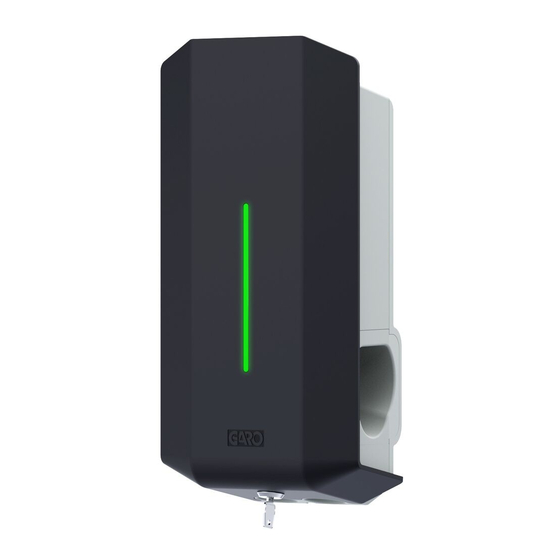
IEC 61851-1 and IEC TS 61439-7. The product complies with IP Code IP44, with a closed front. It is to be fitted to a wall or GARO Wallbox stand, and all installation must be carried out by an authorized installer and comply with local country installation regulations. - Page 32 End User Instruction The status of the GLB-Wallbox can be obtained from the color of the Indication light (D). Solid green light: charger ready, vehicle not connected. Flashing green light: device connected to vehicle eg. status Rapid flashing green: device waiting for authorization eg. RFID tag Shifting blue light intensity: device connected to vehicle, charging in progress Solid blue light: RFID accepted - waiting to start charging...
-
Page 33: Resetting/Conditioning Of Rccb Or Rcbo
End User Instruction Resetting/Conditioning of RCCB or RCBO If the GLB-wallbox is equipped with a RCCB or RCBO (H) (figure 31). In the event of overload/earth fault, these can be tripped. These components must also be conditioned every 6 months. Procedure for resetting/conditioning: 1. -
Page 34: Connecting To The Wallbox's Wi-Fi Access Point (Ap)
End User Instruction Connecting to the wallbox’s Wi-Fi access point (AP) NOTE: Only for GLB-Wallboxes with communication card installed 1. Make sure that the GLB Wallbox is turned on. 2. Check the Serial no./SSID and password on the label which can be found both under the sliding cover and inside the wallbox, see (figure 3) (figure 9). -
Page 35: Web Interface
(Due to continuous development, there might be more features in the web-interface than listed below and the pictures can vary) Warning! GARO recommend that settings only are made by a person with enough knowledge of this product. Wrong settings can cause disturbances or overload of your electrical installation. Note: When the GLB wallbox is connected to your local network, you should use the address chargebox. - Page 36 End User Instruction Main menu Doubleclick on the GARO symbol and extended information shows...
-
Page 37: Dynamic Load Management (Dlm) Settings In The Web Interface (1Pcs Installed Dlm Energymeter)
End User Instruction Dynamic Load Management (DLM) settings in the web interface (1pcs installed DLM energymeter) All load balancing settings in groups are carried out via the GLB-Wallbox’s web interface. The DLM meter connected – Group configuration’ option can be found under Settings. The Fuse rating contract can be set (A), as can the value of the power rating contract (kW), where relevant. -
Page 38: Dynamic Load Management (Dlm) Settings In The Web Interface (2Pcs Installed Dlm Energymeter)
End User Instruction Dynamic Load Management (DLM) settings in the web interface (2pcs installed DLM energymeter) A. Select current or power limitation. Set maximum current (A) or power (kW). C. In the case of a single-phase charger, if the charger is to be controlled by load balancing, the phase assignation must be set. -
Page 39: Rfid Settings In The Web Interface
End User Instruction RFID settings in the web interface Activating and deleting RFID tags When RFID is activated, you can choose ‘Add new tag”. You can now manually register the tag number in the ‘RFID Number’ field. 2. Click ‘Save’. Note: when a group of GLB-Wall boxes are connected, you can specify RFID-tag for an individual GLB-Wallbox. -
Page 40: Connect Glb-Wallbox To A Local Network Via Wi-Fi
(figure 42) Choose to connect via router. Enter your network name/SSID. Enter your network password Press save. NOTE! When the GLB Wallbox is connected to a local network, use the adress chargebox.garo.se in your web browser and follow the instructions... -
Page 41: Connect Glb-Wallbox To A Local Network Via Ethernet Using Dhcp-Server
(figure 43) (figure 44) Choose to obtain IP-address automatically in the Ethernet-settings. Current IP-address is shown Press save NOTE! When the GLB Wallbox is connected to a local network, use the adress chargebox.garo.se in your web browser and follow the instructions. -
Page 42: Connect Glb-Wallbox To A Local Network Via Ethernet Using Static
10 minutes. (figure 45) (figure 46) Choose Static IP. Enter IP-address. Enter Netmask. Enter Gateway. Save. NOTE! When the GLB Wallbox is connected to a local network, use the adress chargebox.garo.se in your web browser and follow the instructions. -
Page 43: Firmware Update Process For Glb Wallbox Connected To Internet Via Wifi Or Lan
End User Instruction Firmware update process for GLB Wallbox connected to internet via Wifi or LAN Login to your GLB-wallbox via web-browser and press button “Check for updates” and then follow the instructions. NOTE! This process require that you have connected your GLB-Wallbox to internet via Wifi or LAN in the settings. -
Page 44: Care
End User Instruction Care Do not install or use the GLB Wallbox near flammable, explosive, harsh, or combustible materials, chemicals, or vapors. Turn off input power at the circuit breaker before installing, configuring or cleaning of the GLB Wallbox. Never spray water or any other liquid directly at the GLB Wallbox. Never spray any liquid onto the charge handle or submerge the charge handle in liquid. -
Page 45: Troubleshooting
End User Instruction Troubleshooting Indication Type of fault Measure Solid red light RCCB has tripped or EV Reset. Refer to section on resetting the earth check error is detected. residual-current or personal protective current breaker. Solid red light for 3 sec RFID tag not accepted. Red fast flash DC current >6mA - charging has stopped. - Page 46 End User Instruction Indication Type of fault Measure One quick white flash Indicate an error in DLM repeating every minute function. RFID accepted - waiting to Solid blue light start charging. EV charging in progress. Shifting blue intensity Shifting red/blue Software upgrade in progress.
-
Page 47: Technical Data
End User Instruction Technical data Specifications Product type: all GLB models Standards/directives: IEC 61851-1 and IEC TS 61439-7 Installation: on wall Rated Voltage: 230V/400 50Hz Installation method: Wall mounted Recommended installation 0,5-1,5m above ground height: Electrical installation TT-, TN- and IT system method: Charging type: Mode 3... - Page 48 GARO AB Box 203, SE–335 25 Gnosjö Phone: +46 (0) 370 33 28 00 info@garo.se garo.se...
Need help?
Do you have a question about the Wallbox GLB Series and is the answer not in the manual?
Questions and answers