Table of Contents
Advertisement
Quick Links
Advertisement
Table of Contents

Related Manuals for GARO Wallbox GHL


Summary of Contents for GARO Wallbox GHL
- Page 1 GARO Wallbox GHL 380175-5 Assembly instructions / End User Instructions (en)
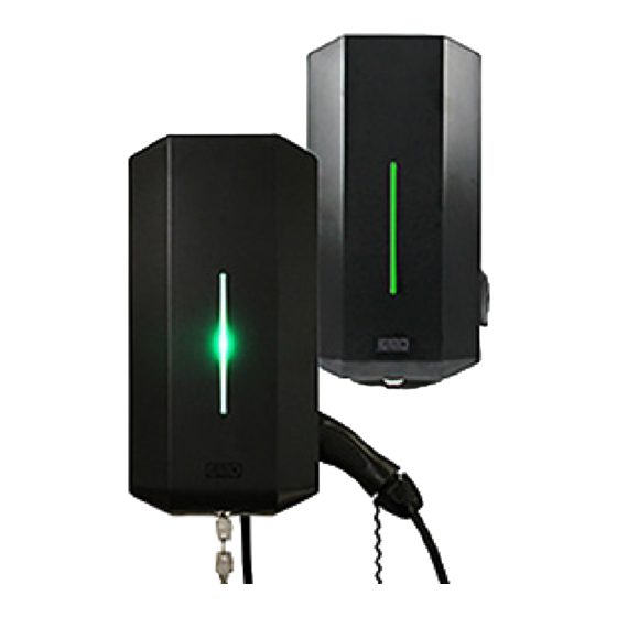
- Page 2 GARO Wallbox with cable and connector, type 1 or 2 (figure 1) Front cover Cover Back panel Indication light Connector type 1 or 2 Type 2 socket outlet RCCB (Residual Current Circuit Breaker) or RCBO (Residual Current Breaker with Overcurrent Protection)
- Page 3 GARO Wallbox with type 2 socket outlet (figure 3) (figure 2)
-
Page 5: Table Of Contents
TABLE OF CONTENTS About this manual Safety Information Technical data Mainboard Simplified Connetion Diagram Dimensional drawing Assembly instructions for installer Box Contents Tools and Materials Required Step-by-Step Installation Reducing the charging current End User instruction Charging electric vehicles Resetting/Conditioning of RCCB or RCBO Care Troubleshooting Index... -
Page 7: About This Manual
Garo Wallbox, models GHL. This document contains general descriptions which are verified to be accurate at the time of printing. However, because continuous improvement is a goal at GARO, we reserve the right to make product modifications at any time. -
Page 8: Safety Information
Safety Information Safety Information Hazard categories and special symbols Read these instructions carefully before trying to install, operate, or maintain it. Save the manual for future use. Indicates a potentially hazardous situation which could result in death or serious injury Indicates a potentially hazardous situation which could result in minor or moderate injury Indicates practices that do not involve the risk of bodily injury... - Page 9 Safety Information The GHL Wallbox must be grounded through a permanent wiring system. Do not install or use the GHL Wallbox near flammable, explosive, harsh, or combustible materials, chemicals, or vapors. Turn off input power at the circuit breaker before installing, configure or cleaning the GHL Wallbox.
- Page 10 Safety Information Cautions Do not use private power generators as a power source for charging. Incorrect installation and testing of the GHL Wallbox could potentially damage either the vehicle’s Battery and/or the GHL Wallbox itself. Do not operate the GHL Wallbox in temperatures outside its operating range – see technical data.
-
Page 11: Technical Data
Technical data Specifications Product type: all GHL models Standards/directives: IEC 61851-1 and IEC TS 61439-7 Installation: on wall or on GARO Wallbox stand Voltage rating: 230V/400 50Hz Installation systems: TT, TN and IT systems Charging type: Mode 3 IP classification:... -
Page 12: Mainboard Simplified Connetion Diagram
Mainboard Simplified Connection Diagram Mainboard Simplified Connetion Diagram Valid for 1- and 3-phase installation. Socketoutlet/ Vehicle connector RCCB Fuse FB Contactor FB Contactor Ctr Contactor Ctr Interlock on K101 socketoutlet PE N L Out + Motor Out - +12V K402 RFID K401 K302... -
Page 13: Dimensional Drawing
Dimensional drawing Dimensional drawing (figure 5) -
Page 14: Assembly Instructions For Installer
ASSEMBLY INSTRUCTIONS FOR INSTALLER Congratulations on selecting a GARO Wallbox and contributing to a better environment. The GARO Wallbox is an AC charger enabling Mode 3 charging which complies fully with the requirements of IEC 61851-1 and IEC TS 61439-7. - Page 15 Assembly instructions for installer (table 1) Chargers without RCCB or RCBO included in the enclosure must have Residual Current protection and must be protected with a max 32A fuse in the supply distribution box. Chargers without RCCB Type B fitted in the enclosure must in accordance to IEC 60364-7-722 be protected with a Residual Current Device (RCD) Type B.
-
Page 16: Box Contents
Assembly instructions for installer / Box Contents Box Contents Drill template GHL Wallbox (see the back of the box) GARO Wallbox 380175-3 Assembly instructions/User Instructions (EN) Keys Manual Language labels... -
Page 17: Tools And Materials Required
Assembly instructions for installer / Tools and material required Tools and Materials Required Before installing the Garo Wallbox, gather the folllowing tools and materials: • Pencil or marker • Hole punch (optional, to push through cardboard template) • Wire cutter •... -
Page 18: Step-By-Step Installation
Assembly instructions for installer / Step-by-Step installation Step-by-Step Installation (figure 7) Read Safety Instructions All installation must be carried out by an authorised installer and comply with local installation regulations. Ensure the supply cable is powerless. Turn off input power at the circuit breaker before installing, configure or cleaning the GHL Wallbox. - Page 19 Assembly instructions for installer / Step-by-Step installation (figure 8) Loosen the seven screws and carefully remove the cover from the back panel.
- Page 20 Assembly instructions for installer / Step-by-Step installation Connection of phases for 3-phase charger to 3-phase system as below. When connecting a 3-phase charger to 1-phase system connect phase to L1. (figure 9)
- Page 21 Assembly instructions for installer / Step-by-Step installation Screw the back panel onto the wall using three screws suitable for the wall surface. See red arrows in figure 9. Feed the cable through the cable inlet. Be careful not to damage the circuit boards or components during installation.
- Page 22 Assembly instructions for installer / Step-by-Step installation 7 x T20 label explaining charger status indication language label is placed on the side english information label (figure 10) Carefully place the cover in position from the front. Ensure the inserts on the right hand side fit into the groove and the cover is perfectly positioned all around.
- Page 23 Assembly instructions for installer / Step-by-Step installation (figure 11) Re-install the front cover by feeding it in from below. Lock the front cover with the key.
- Page 24 Assembly instructions for installer / Step-by-Step installation (figure 12) Connect the power and ensure the indication light is solid green. If, not refer to the section on: Troubleshooting When solid green light is shown, the charger is ready for use.
-
Page 25: Reducing The Charging Current
Assembly instructions for installer / Reducing the charging current Reducing the charging current Turn off input power at the circuit breaker before installing, configure or cleaning the GHL Wallbox. All installation must be carried out by an authorised installer and comply with local installation regulations. -
Page 27: End User Instruction
End user instrucion END USER INSTRUCTION (figure 14) (figure 15) - Page 28 End user instrucion / Charging electric vehicles This equipment should not be used by anyone (including children) with reduced physical, sensory or mental capacity, or anyone lacking in experience or knowledge, unless they are provided with supervision or prior instruction in how to use the equipment by the person responsible for their safety.
-
Page 29: Charging Electric Vehicles
End user instrucion / Charging electric vehicles Charging electric vehicles Connect the wallbox to the vehicle using the cable. When charging starts, solid blue light indicates charging in progress. Stop charging. As a rule, the wallbox socket and vehicle inlet locks the cable. As a result, charging must be stopped from the vehicle before the cable is removed. - Page 30 End user instrucion / Resetting/Conditioning of RCCB or RCBO (figure 16)
-
Page 31: Resetting/Conditioning Of Rccb Or Rcbo
End user instrucion / Resetting/Conditioning of RCCB or RCBO Resetting/Conditioning of RCCB or RCBO Do not modify the equipment installation or any part of the product. Do not touch the GHL Wallbox’s end terminals with fingers or any other objects. Do not insert foreign objects into any part of the GHL Wallbox. -
Page 32: Care
End user instrucion / Care Care Do not install or use the GHL Wallbox near flammable, explosive, harsh, or combustible materials, chemicals, or vapors. Turn off input power at the circuit breaker before installing or cleaning the GHL Wallbox. Never spray water or any other liquid directly at the GHL Wallbox. Never spray any liquid onto the charge handle or submerge the charge handle in liquid. -
Page 33: Troubleshooting
End user instrucion / Troubleshooting Troubleshooting Indication Type of fault Measure Constant red light The residual-current or Reset. Refer to section on personal protective current Resetting the RCCB or RCBO breaker has been tripped. Flashing red light Fault in sockets Contact a qualified electrician. -
Page 34: Index
Index INDEX Symbols Application temperature 11 Assembly instructions for installer 14 Indication light 2 Installation 11,18 Back panel 2 Installation height 11 Box Contents 16 Installation systems 11 IP classification 11 Care 32 Cautions 10 Charging electric vehicles 29 Charging type 11 Key 2 Cleaning the Charging Station 32 Connector type 1 or 2 2... - Page 35 Index PCB Connetion Diagram 12 Warnings 8 Weight 11 RCBO 2 RCCB 2 Reducing the charging current 25 Resetting/Conditioning 31 Safety Information 8 Socket outlet 2 Specifications 11 Standards 11 Step-by-Step Installation 18 Storage temperature 11 Technical data 11 Tools and Materials Required 17 Troubleshooting 33 Type 2 socket outlet 2 Voltage rating 11...
- Page 36 GARO AB Box 203, SE–335 25 Gnosjö Tel: +46 (0) 370 33 28 00 Fax +46 (0) 370 33 28 50 info@garo.se garo.se...
Need help?
Do you have a question about the Wallbox GHL and is the answer not in the manual?
Questions and answers
Does the wall box have a pairing code? My car manual is asking for this. It should have been on the package, which had been thrown away some 8 years ago.